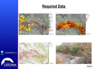
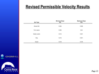
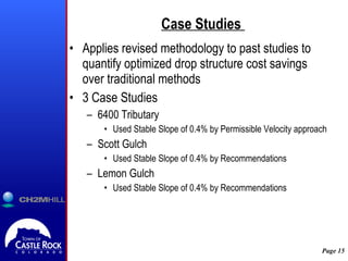
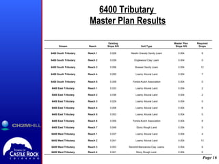
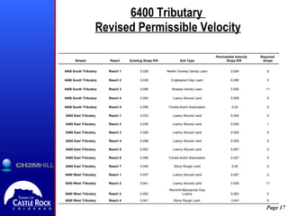
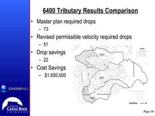
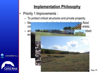
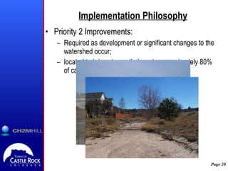
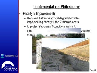
Is It Stable Yet? A Lessons Learned Approach to Predicting Long Term Stable Channel Slopes 2009 CASFM Conference Crested Butte, CO. September 16 – 18, 2009 Alan Turner P.E., CFM, CH2M HILL  J. David Van Dellen, P.E., CFM, Town of Castle Rock Pieter Van Ry, P.E., CFM, Town of Castle Rock Mark Glidden, P.E., CH2M HILL
Objectives Overview of the  Castle Rock Master Planning process and history Development and implementation of the preferred stream stability methodology Philosophy and approach to CIP implementation program Potential stream stability cost savings for the Town
Master Planning in Castle Rock Town characteristics Steep terrain Diverse soil types Rapid growth Stormwater Master Plan  - January 2004 Created Town Stormwater Utility Used to create master planning and CIP implementation budgets
Goals of Castle Rock Master Planning Stormwater Enterprise Fund Capital Improvement Program Development Guidance Develop FEMA Compliant Flood Hazard Information Preliminary Wetlands Inventory Determine long-term stable channel grade
Available Methodologies for  Stream Stability   Regulation and Recommendations UDFCD Town of Castle Rock Approximate methodologies Sediment Transport Calculations Permissible velocity Detailed methodologies HEC-6 HEC-RAS
Traditional Permissible Velocity Analysis Looks at basin wide stream stability Utilizes one stable channel grade based on  Generalized soil conditions  Generalized hydraulic conditions Generalized vegetative Cover Conservative one size fits all methodology
Revised Permissible Velocity Analysis Developed during the Omni, Industrial, Westfield, and Dawson Tributary Master Plans Looks at a reach by reach stream stability Groups similar stream characteristics by reach Soils Vegetation Hydraulic properties Develops a stable channel grade: By reach By soil type Allows for an optimized placement of drop structures
Required Data
Revised Permissible Velocity Methodology 3 “Typical Sections” selected normal depth assumption no interference from hydraulic structures Velocity computed for cross section Slope adjusted until permissible velocity reached  Slopes for each typical section averaged to determine stable slope for each reach.
 
Permissible Velocity Values *  Fortier and Scobey (1926) **  Known et all (1977) *** SCS (1954) and UDFCD (2006) 6.8 6.0 5.5 5.3 5.0 3.8 SC  Hilly gravelly land and pits gravel and Stony rough land Hg, GP, Su Graded Loam to Cobbles 6.8 4.9 4.6 3.9 2.5 - 3.5 1.75 - 2.0 SC  Peyton Pring Crowfoot and Kutch Sandy Loams and Complex PpE, PrE2, KtE Sandy Loam 6.8 4.9 4.6 3.9 3.5 - 5 2.0 - 3.8 CL Loamy Alluvial Land, Sandy wet Alluvial Land, and Sampson Loam Lo, Lu, SE, Sd, Se, St Alluvial Silt 6.8 6.0 5.5 5.3 5.0 3.4 CL Kutch Clay Loam, Jarre Brusset and Fondis Kutch Association, Fondis Clay Loam and Pits Clay KuD, Jb, Fu, CP, FoD Stiff Clay 6.8 4.9 4.6 3.9 2.7 - 3.5 1.7 - 2.5 SC-SM  Bresser, Bresser Truckton, Crawfoot Tomah, and Newlin Sandy Loams BrD, Bte, BrB Cre, NeE Ordinary Firm Loam Grass Lined *** Flow Depth 8 to 10 feet** Flow Depth 5 to 8 feet** Flow Depth 3 to 5 feet** Water Transporting Colloidal Silt* Clear Water* USCS NRCS Soil Description NRCS Soil Type Applied  Permissible Velocities (fps) Soil Types within Study Area Soil Description Fortier and Scobey (1926)  
Revised Permissible Velocity Results 0.041 Clay, Sandy Loams 4 Westfield 0.012 Firm Loams 2,3 Westfield 0.006 Firms Loams, Silt 1 Westfield 0.018 Firm Loams, Sandy Loams, Gravel 4,5,IT1 Industrial 0.004 Firm Loams 1,2,3 Industrial 0.013 Clay, Firm Loams, Sandy Loams 1,2 Tributary to Omni 0.015 Sandy Loams, Clay 6 Omni 0.010 Firm Loams 3,4,5 Omni 0.004 Alluvial Silt, Firm Loams 1,2 Omni Stable Slope (ft/ft) Soil Type Reaches Tributary 0.020 Stiff Clay, Firm Loams, Sandy Loams 6.7 South Dawson 0.007 Firm Loams 1,2,3,4,5 South Dawson 0.004 Alluvial Silt, Firm Loams 1,2,3 North Dawson Stable Slope (ft/ft) Soil Type Reaches Tributary
Revised Permissible Velocity Results 0.018 0.018 Gravel 0.041 0.013 Clay 0.041 0.013 Sandy Loams 0.02 0.004 Firm Loams 0.006 0.004 Alluvial Silt Maximum Slope Ft/ft Minimum Slope ft/ft Soil Type
Revised Permissible Velocity  Reality Check
Case Studies  Applies revised methodology to past studies to quantify optimized drop structure cost savings over traditional methods 3 Case Studies 6400 Tributary Used Stable Slope of 0.4% by Permissible Velocity approach Scott Gulch Used Stable Slope of 0.4% by Recommendations Lemon Gulch Used Stable Slope of 0.4% by Recommendations
6400 Tributary  Master Plan Results 0 0.004 Stony Rough Land  0.041 Reach 4 6400 West Tributary 9 0.004 Renohill-Manzanola Clay Loams 0.053 Reach 3 6400 West Tributary 13 0.004 Loamy Alluvial Land 0.041 Reach 2 6400 West Tributary 4 0.004 Loamy Alluvial Land 0.037 Reach 1 6400 West Tributary 0 0.004 Stony Rough Land 0.049 Reach 7 6400 East Tributary 9 0.004 Fondis-Kutch Association 0.059 Reach 6 6400 East Tributary 0 0.004 Loamy Alluvial Land 0.053 Reach 5 6400 East Tributary 6 0.004 Loamy Alluvial Land 0.058 Reach 4 6400 East Tributary 0 0.004 Loamy Alluvial Land 0.029 Reach 3 6400 East Tributary 2 0.004 Loamy Alluvial Land 0.036 Reach 2 6400 East Tributary 2 0.004 Loamy Alluvial Land 0.033 Reach 1 6400 East Tributary 0 0.004 Fondis-Kutch Association 0.059 Reach 5 6400 South Tributary 7 0.004 Loamy Alluvial Land 0.050 Reach 4 6400 South Tributary 12 0.004 Bresser Sandy Loam 0.056 Reach 3 6400 South Tributary 0 0.004 Englewood Clay Loam 0.039 Reach 2 6400 South Tributary 9 0.004 Newlin Gravely Sandy Loam 0.028 Reach 1 6400 South Tributary Required Drops Master Plan  Slope ft/ft Soil Type Existing Slope ft/ft Reach Stream
6400 Tributary  Revised Permissible Velocity 0   0.041 Stony Rough Land  0.041 Reach 4 6400 West Tributary 0 0.053 Renohill-Manzanola Clay Loams 0.053 Reach 3 6400 West Tributary 11 0.009 Loamy Alluvial Land 0.041 Reach 2 6400 West Tributary 2 0.007 Loamy Alluvial Land 0.037 Reach 1 6400 West Tributary 0 0.05 Stony Rough Land 0.049 Reach 7 6400 East Tributary 5 0.037 Fondis-Kutch Association 0.059 Reach 6 6400 East Tributary 0 0.007 Loamy Alluvial Land 0.053 Reach 5 6400 East Tributary 5 0.005 Loamy Alluvial Land 0.058 Reach 4 6400 East Tributary 0 0.005 Loamy Alluvial Land 0.029 Reach 3 6400 East Tributary 1 0.005 Loamy Alluvial Land 0.036 Reach 2 6400 East Tributary 2 0.004 Loamy Alluvial Land 0.033 Reach 1 6400 East Tributary 0 0.02 Fondis-Kutch Association 0.059 Reach 5 6400 South Tributary 5 0.009 Loamy Alluvial Land 0.050 Reach 4 6400 South Tributary 11 0.005 Bresser Sandy Loam 0.056 Reach 3 6400 South Tributary 0 0.006 Englewood Clay Loam 0.039 Reach 2 6400 South Tributary 9 0.004 Newlin Gravely Sandy Loam 0.028 Reach 1 6400 South Tributary Required  Drops Permissible Velocity Slope ft/ft Soil Type Existing Slope ft/ft Reach Stream
6400 Tributary Results Comparison Master plan required drops 73 Revised permissible velocity required drops 51 Drop savings 22 Cost Savings $1,650,000
Implementation Philosophy Priority 1 Improvements : To protect critical structures and private property; Necessary now to mitigate damage to existing flood control facilities and environmentally sensitive areas; and at locations with active head cutting or streambed erosion.
Implementation Philosophy Priority 2 Improvements:  Required as development or significant changes to the watershed occur; located to bring stream thalwag to approximately 80% of calculated stable slope.
Implementation Philosophy Priority 3 Improvements Required if streams exhibit degradation after implementing priority 1 and 2 improvements; to protect structures if conditions warrant;  if major changes in the watershed occur that were not originally considered.
Prioritizing Improvements  Based on field observations Localized areas of instability Damage to existing infrastructure Based on stream stability analysis Used to determine stable channel grade Used to place proposed drop structures Based hydraulic analysis Used to check existing conveyance Used to size future infrastructure
Phased Cost Approach Total Cost of all improvements for Omni Trib. $6,935,800 Total Cost of Priority 1 Improvements $2,019,700 Priority 1 Improvements are 29% of total cost Total Cost with Priority 2 Improvements $4,839,900 80% of the stream stabilized with Priority 1 and Priority 2 Improvements 70% of the total cost expenditure May never need to implement priority 3 improvements
Conclusion  Cost savings of modified permissible velocity stream stability analysis Quick and cost effective with a minimum of required data Allows for a varied slope to optimize required drop placement Cost savings of phased approach for improvement implementation Allows for implementation from multiple stakeholders Identifies structures key to public safety and health Allows for a long term phased approach to stream improvement
Questions?

CASFM 2009 Presentation On Stream Stability

  • 1.
    Is It StableYet? A Lessons Learned Approach to Predicting Long Term Stable Channel Slopes 2009 CASFM Conference Crested Butte, CO. September 16 – 18, 2009 Alan Turner P.E., CFM, CH2M HILL J. David Van Dellen, P.E., CFM, Town of Castle Rock Pieter Van Ry, P.E., CFM, Town of Castle Rock Mark Glidden, P.E., CH2M HILL
  • 2.
    Objectives Overview ofthe Castle Rock Master Planning process and history Development and implementation of the preferred stream stability methodology Philosophy and approach to CIP implementation program Potential stream stability cost savings for the Town
  • 3.
    Master Planning inCastle Rock Town characteristics Steep terrain Diverse soil types Rapid growth Stormwater Master Plan - January 2004 Created Town Stormwater Utility Used to create master planning and CIP implementation budgets
  • 4.
    Goals of CastleRock Master Planning Stormwater Enterprise Fund Capital Improvement Program Development Guidance Develop FEMA Compliant Flood Hazard Information Preliminary Wetlands Inventory Determine long-term stable channel grade
  • 5.
    Available Methodologies for Stream Stability Regulation and Recommendations UDFCD Town of Castle Rock Approximate methodologies Sediment Transport Calculations Permissible velocity Detailed methodologies HEC-6 HEC-RAS
  • 6.
    Traditional Permissible VelocityAnalysis Looks at basin wide stream stability Utilizes one stable channel grade based on Generalized soil conditions Generalized hydraulic conditions Generalized vegetative Cover Conservative one size fits all methodology
  • 7.
    Revised Permissible VelocityAnalysis Developed during the Omni, Industrial, Westfield, and Dawson Tributary Master Plans Looks at a reach by reach stream stability Groups similar stream characteristics by reach Soils Vegetation Hydraulic properties Develops a stable channel grade: By reach By soil type Allows for an optimized placement of drop structures
  • 8.
  • 9.
    Revised Permissible VelocityMethodology 3 “Typical Sections” selected normal depth assumption no interference from hydraulic structures Velocity computed for cross section Slope adjusted until permissible velocity reached Slopes for each typical section averaged to determine stable slope for each reach.
  • 10.
  • 11.
    Permissible Velocity Values* Fortier and Scobey (1926) ** Known et all (1977) *** SCS (1954) and UDFCD (2006) 6.8 6.0 5.5 5.3 5.0 3.8 SC Hilly gravelly land and pits gravel and Stony rough land Hg, GP, Su Graded Loam to Cobbles 6.8 4.9 4.6 3.9 2.5 - 3.5 1.75 - 2.0 SC Peyton Pring Crowfoot and Kutch Sandy Loams and Complex PpE, PrE2, KtE Sandy Loam 6.8 4.9 4.6 3.9 3.5 - 5 2.0 - 3.8 CL Loamy Alluvial Land, Sandy wet Alluvial Land, and Sampson Loam Lo, Lu, SE, Sd, Se, St Alluvial Silt 6.8 6.0 5.5 5.3 5.0 3.4 CL Kutch Clay Loam, Jarre Brusset and Fondis Kutch Association, Fondis Clay Loam and Pits Clay KuD, Jb, Fu, CP, FoD Stiff Clay 6.8 4.9 4.6 3.9 2.7 - 3.5 1.7 - 2.5 SC-SM Bresser, Bresser Truckton, Crawfoot Tomah, and Newlin Sandy Loams BrD, Bte, BrB Cre, NeE Ordinary Firm Loam Grass Lined *** Flow Depth 8 to 10 feet** Flow Depth 5 to 8 feet** Flow Depth 3 to 5 feet** Water Transporting Colloidal Silt* Clear Water* USCS NRCS Soil Description NRCS Soil Type Applied Permissible Velocities (fps) Soil Types within Study Area Soil Description Fortier and Scobey (1926)  
  • 12.
    Revised Permissible VelocityResults 0.041 Clay, Sandy Loams 4 Westfield 0.012 Firm Loams 2,3 Westfield 0.006 Firms Loams, Silt 1 Westfield 0.018 Firm Loams, Sandy Loams, Gravel 4,5,IT1 Industrial 0.004 Firm Loams 1,2,3 Industrial 0.013 Clay, Firm Loams, Sandy Loams 1,2 Tributary to Omni 0.015 Sandy Loams, Clay 6 Omni 0.010 Firm Loams 3,4,5 Omni 0.004 Alluvial Silt, Firm Loams 1,2 Omni Stable Slope (ft/ft) Soil Type Reaches Tributary 0.020 Stiff Clay, Firm Loams, Sandy Loams 6.7 South Dawson 0.007 Firm Loams 1,2,3,4,5 South Dawson 0.004 Alluvial Silt, Firm Loams 1,2,3 North Dawson Stable Slope (ft/ft) Soil Type Reaches Tributary
  • 13.
    Revised Permissible VelocityResults 0.018 0.018 Gravel 0.041 0.013 Clay 0.041 0.013 Sandy Loams 0.02 0.004 Firm Loams 0.006 0.004 Alluvial Silt Maximum Slope Ft/ft Minimum Slope ft/ft Soil Type
  • 14.
  • 15.
    Case Studies Applies revised methodology to past studies to quantify optimized drop structure cost savings over traditional methods 3 Case Studies 6400 Tributary Used Stable Slope of 0.4% by Permissible Velocity approach Scott Gulch Used Stable Slope of 0.4% by Recommendations Lemon Gulch Used Stable Slope of 0.4% by Recommendations
  • 16.
    6400 Tributary Master Plan Results 0 0.004 Stony Rough Land  0.041 Reach 4 6400 West Tributary 9 0.004 Renohill-Manzanola Clay Loams 0.053 Reach 3 6400 West Tributary 13 0.004 Loamy Alluvial Land 0.041 Reach 2 6400 West Tributary 4 0.004 Loamy Alluvial Land 0.037 Reach 1 6400 West Tributary 0 0.004 Stony Rough Land 0.049 Reach 7 6400 East Tributary 9 0.004 Fondis-Kutch Association 0.059 Reach 6 6400 East Tributary 0 0.004 Loamy Alluvial Land 0.053 Reach 5 6400 East Tributary 6 0.004 Loamy Alluvial Land 0.058 Reach 4 6400 East Tributary 0 0.004 Loamy Alluvial Land 0.029 Reach 3 6400 East Tributary 2 0.004 Loamy Alluvial Land 0.036 Reach 2 6400 East Tributary 2 0.004 Loamy Alluvial Land 0.033 Reach 1 6400 East Tributary 0 0.004 Fondis-Kutch Association 0.059 Reach 5 6400 South Tributary 7 0.004 Loamy Alluvial Land 0.050 Reach 4 6400 South Tributary 12 0.004 Bresser Sandy Loam 0.056 Reach 3 6400 South Tributary 0 0.004 Englewood Clay Loam 0.039 Reach 2 6400 South Tributary 9 0.004 Newlin Gravely Sandy Loam 0.028 Reach 1 6400 South Tributary Required Drops Master Plan Slope ft/ft Soil Type Existing Slope ft/ft Reach Stream
  • 17.
    6400 Tributary Revised Permissible Velocity 0   0.041 Stony Rough Land  0.041 Reach 4 6400 West Tributary 0 0.053 Renohill-Manzanola Clay Loams 0.053 Reach 3 6400 West Tributary 11 0.009 Loamy Alluvial Land 0.041 Reach 2 6400 West Tributary 2 0.007 Loamy Alluvial Land 0.037 Reach 1 6400 West Tributary 0 0.05 Stony Rough Land 0.049 Reach 7 6400 East Tributary 5 0.037 Fondis-Kutch Association 0.059 Reach 6 6400 East Tributary 0 0.007 Loamy Alluvial Land 0.053 Reach 5 6400 East Tributary 5 0.005 Loamy Alluvial Land 0.058 Reach 4 6400 East Tributary 0 0.005 Loamy Alluvial Land 0.029 Reach 3 6400 East Tributary 1 0.005 Loamy Alluvial Land 0.036 Reach 2 6400 East Tributary 2 0.004 Loamy Alluvial Land 0.033 Reach 1 6400 East Tributary 0 0.02 Fondis-Kutch Association 0.059 Reach 5 6400 South Tributary 5 0.009 Loamy Alluvial Land 0.050 Reach 4 6400 South Tributary 11 0.005 Bresser Sandy Loam 0.056 Reach 3 6400 South Tributary 0 0.006 Englewood Clay Loam 0.039 Reach 2 6400 South Tributary 9 0.004 Newlin Gravely Sandy Loam 0.028 Reach 1 6400 South Tributary Required Drops Permissible Velocity Slope ft/ft Soil Type Existing Slope ft/ft Reach Stream
  • 18.
    6400 Tributary ResultsComparison Master plan required drops 73 Revised permissible velocity required drops 51 Drop savings 22 Cost Savings $1,650,000
  • 19.
    Implementation Philosophy Priority1 Improvements : To protect critical structures and private property; Necessary now to mitigate damage to existing flood control facilities and environmentally sensitive areas; and at locations with active head cutting or streambed erosion.
  • 20.
    Implementation Philosophy Priority2 Improvements: Required as development or significant changes to the watershed occur; located to bring stream thalwag to approximately 80% of calculated stable slope.
  • 21.
    Implementation Philosophy Priority3 Improvements Required if streams exhibit degradation after implementing priority 1 and 2 improvements; to protect structures if conditions warrant; if major changes in the watershed occur that were not originally considered.
  • 22.
    Prioritizing Improvements Based on field observations Localized areas of instability Damage to existing infrastructure Based on stream stability analysis Used to determine stable channel grade Used to place proposed drop structures Based hydraulic analysis Used to check existing conveyance Used to size future infrastructure
  • 23.
    Phased Cost ApproachTotal Cost of all improvements for Omni Trib. $6,935,800 Total Cost of Priority 1 Improvements $2,019,700 Priority 1 Improvements are 29% of total cost Total Cost with Priority 2 Improvements $4,839,900 80% of the stream stabilized with Priority 1 and Priority 2 Improvements 70% of the total cost expenditure May never need to implement priority 3 improvements
  • 24.
    Conclusion Costsavings of modified permissible velocity stream stability analysis Quick and cost effective with a minimum of required data Allows for a varied slope to optimize required drop placement Cost savings of phased approach for improvement implementation Allows for implementation from multiple stakeholders Identifies structures key to public safety and health Allows for a long term phased approach to stream improvement
  • 25.