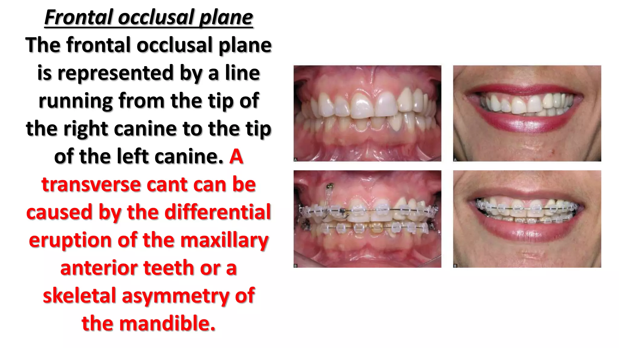
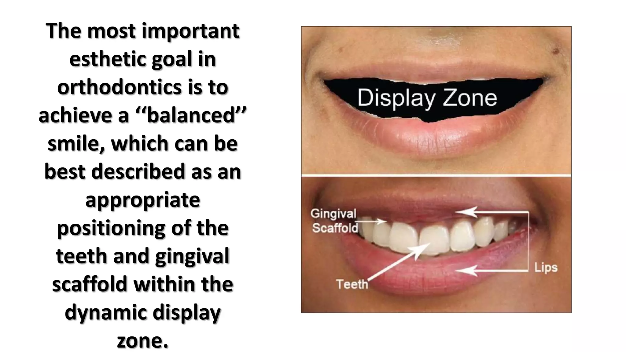
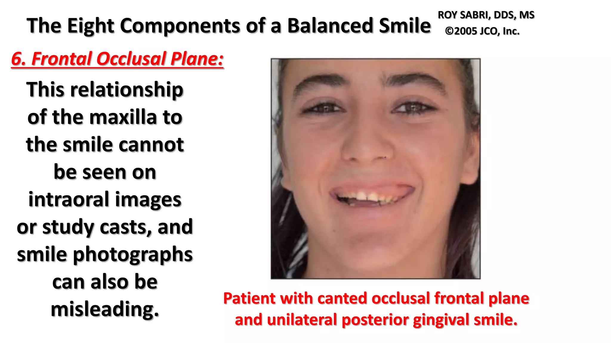
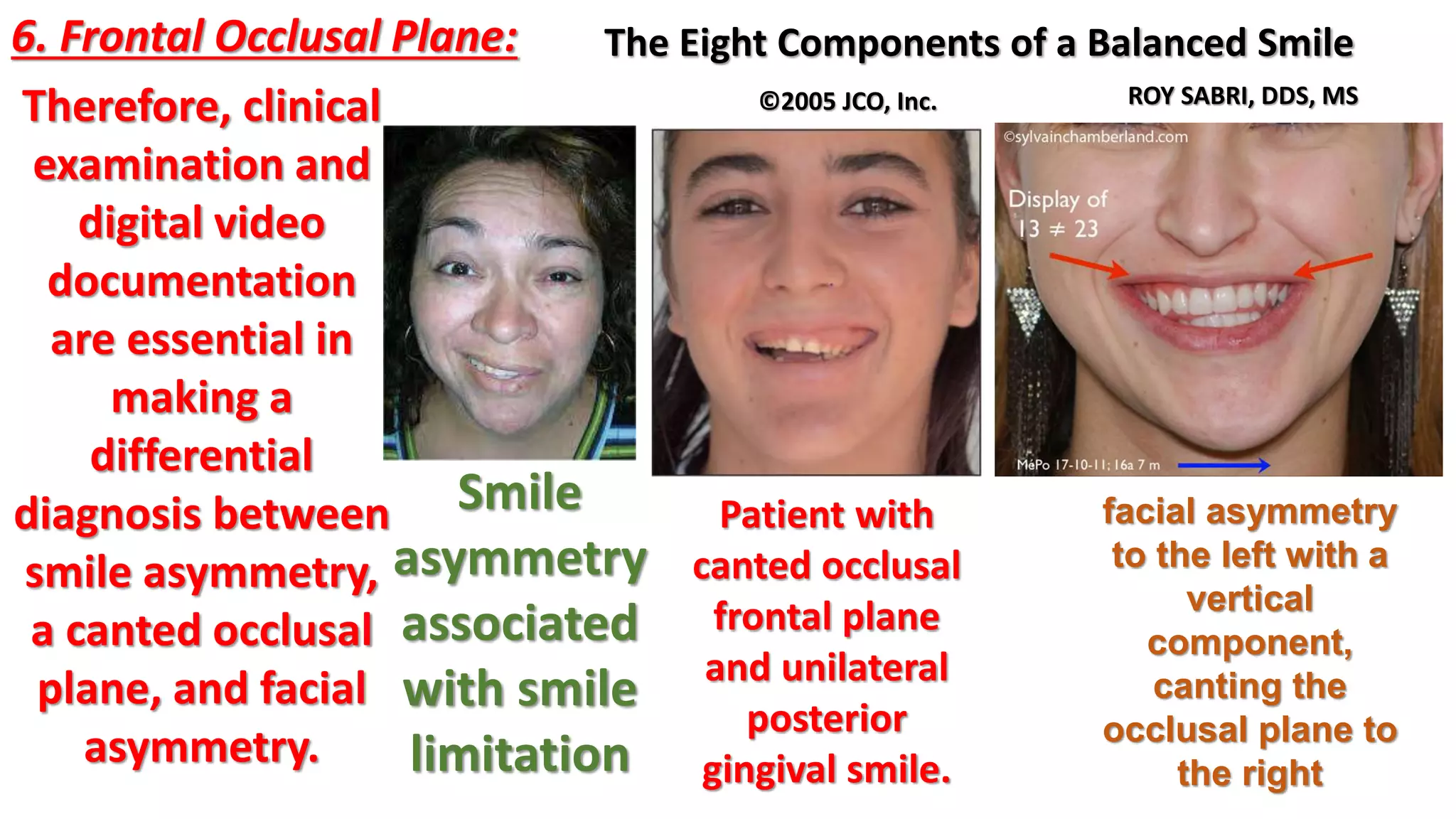
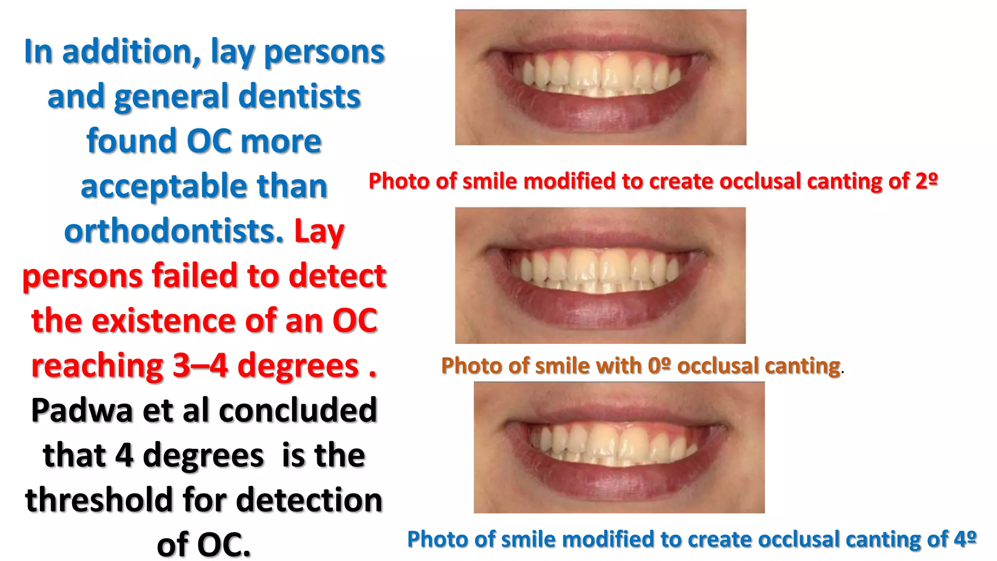
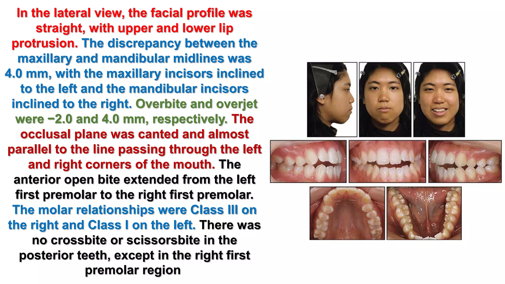
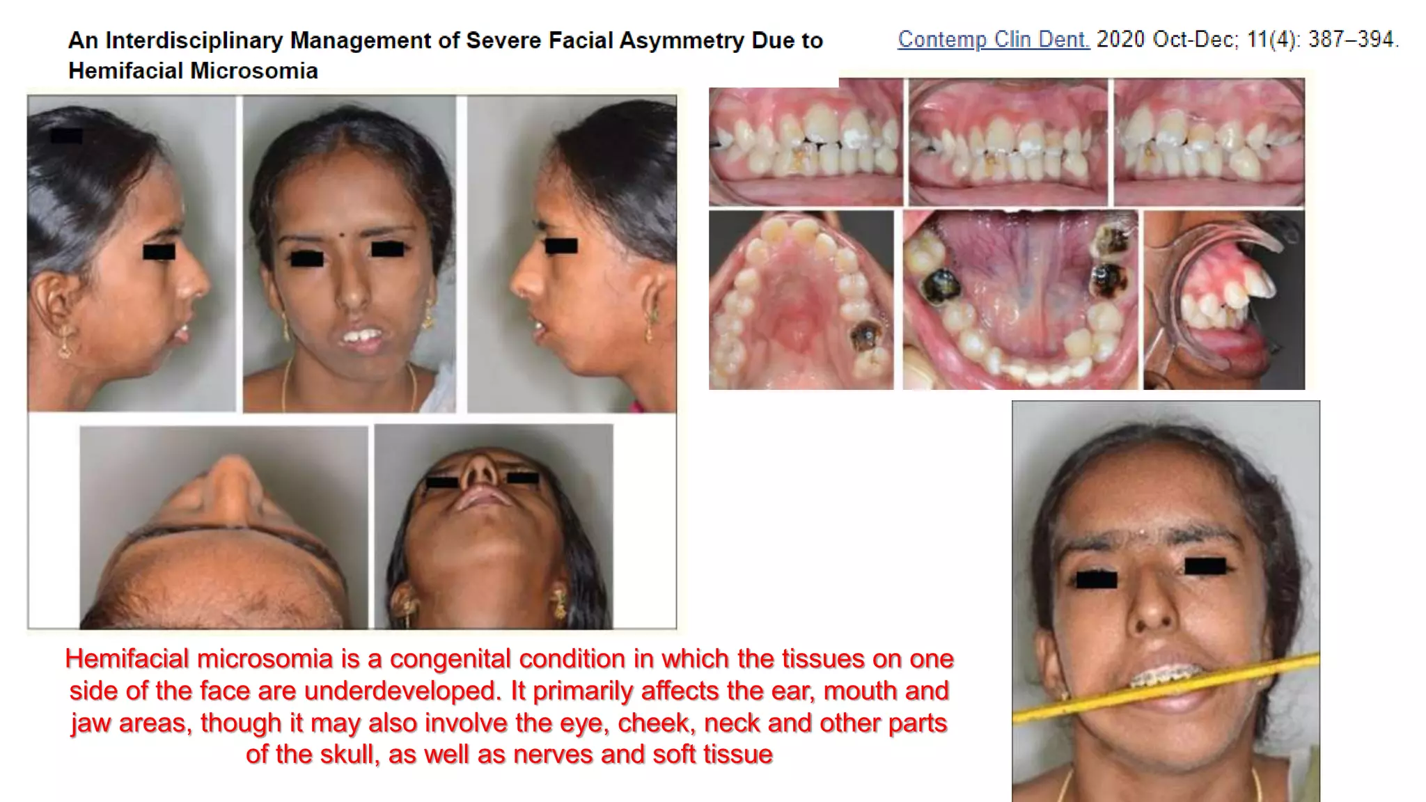
Canted occlusal plane ;etiology
and evaluation
part 1
Dr Maher fouda
Professor of orthodontics
Mansoura Egypt
Turkish J Orthod Vol 27, No 4, 2015
Reference:
Frontal occlusal plane
The frontal occlusal plane
is represented by a line
running from the tip of
the right canine to the tip
of the left canine. A
transverse cant can be
caused by the differential
eruption of the maxillary
anterior teeth or a
skeletal asymmetry of
the mandible.
The most important
esthetic goal in
orthodontics is to
achieve a ‘‘balanced’’
smile, which can be
best described as an
appropriate
positioning of the
teeth and gingival
scaffold within the
dynamic display
zone.
The display zone
are affected by
the size, shape,
position, and
color of the
displayed teeth
as well as the
gingival contour,
buccal corridor,
and framing of
the lips.
Smile components
The Eight Components of a Balanced Smile
ROY SABRI, DDS, MS ©2005 JCO, Inc.
1. Lip Line
Upper Lip Length
Lip Elevation
Vertical Maxillary Height
Crown Height
Vertical Dental Height
Incisor Inclination
2. Smile Arc
Overintrusion of Maxillary Incisors
Cant of the Occlusal Plane
3. Upper Lip Curvature
4. Lateral Negative Space
The Eight Components of a Balanced Smile
ROY SABRI, DDS, MS ©2005 JCO, Inc.
5. Smile Symmetry
6. Frontal Occlusal Plane
7. Dental Components
8. Gingival Components
Cant of the Occlusal Plane:
Extraoral forces,
intermaxillary elastics, and
orthognathic surgery can
affect the cant of the
occlusal plane. If the
maxillary occlusal plane is
canted upward anteriorly,
for instance, the incisal
edges will move away from
the lower lip, resulting in a
nonconsonant smile arc .
Consonant (a) and non-consonant arc of
the smile (b), determined by the upper
incisal line and the internal surface of
the lower lip
Cant of the Occlusal Plane:
Conversely, if the occlusal plane has an
excessive clockwise tilt, the upper incisal
edges will be covered by the lower lip, making
the smile arc less attractive
Retracted
Close Up
Teeth Apart.
Note the Rise and
Cant in the Incisal
plane up to her
right side.
Cant of the Occlusal Plane:
Other factors that can affect
the smile arc are attrition due
to shortening of the central
incisors, habits such as
thumbsucking, excessive
posterior vertical growth
(mostly seen in brachyfacial
patterns), and the lower lip
musculature.
Consonant and nonconsonant
smiles: A , consonant smile with
parallelism between the curvature
of the maxillary incisal edge and
the upper border of lower lip; B ,
nonconsonant smile, with no
parallelism between the curves.
Intraoral
frontal view
depicting
asymmetric
open bite due
to long
persistent
unilateral digit
sucking habit.
Cant of the Occlusal Plane:
Maxillary incisor inclination
affects not only the lip line,
but the smile arc as well,
when the curvature of the
incisal edges does not
coincide with the border of
the lower lip in smiling . Lip line with reduced
incisor display due to
proclined maxillary incisors.
Cant of the Occlusal Plane:
Excessively proclined
incisors will be
associated with an
everted lower lip,
whereas uprighted or
retroclined incisors
will be partially
covered by the lower
lip.
Patient with
canted occlusal
frontal plane
and unilateral
posterior
gingival smile.
The Eight Components of a Balanced Smile
ROY SABRI, DDS, MS
©2005 JCO, Inc.
6. Frontal Occlusal Plane:
Patient with canted occlusal frontal plane
and unilateral posterior gingival smile.
This relationship
of the maxilla to
the smile cannot
be seen on
intraoral images
or study casts, and
smile photographs
can also be
misleading.
The Eight Components of a Balanced Smile
ROY SABRI, DDS, MS
©2005 JCO, Inc.
6. Frontal Occlusal Plane:
Patient with
canted occlusal
frontal plane
and unilateral
posterior
gingival smile.
Therefore, clinical
examination and
digital video
documentation
are essential in
making a
differential
diagnosis between
smile asymmetry,
a canted occlusal
plane, and facial
asymmetry.
Smile
asymmetry
associated
with smile
limitation
facial asymmetry
to the left with a
vertical
component,
canting the
occlusal plane to
the right
The Eight Components of a Balanced Smile
ROY SABRI, DDS, MS
©2005 JCO, Inc.
6. Frontal Occlusal Plane
Having the patient bite on
a tongue blade or a mouth
mirror in the premolar
area during the clinical
examination is a good way
to recognize an
asymmetrical cant of the
maxillary frontal occlusal
plane.
Smile design and
mechanotherapy
must take into
account an
esthetic plane of
occlusion, which is
often different
from the natural
plane of
occlusion.
A. Patient with
asymmetrical
cant of
maxillary
anterior
transverse
occlusal plane.
B. Different
bracket height
on maxillary left
canine vs.
maxillary right
canine. C.
Patient after
treatment.
occlusal cant (OC) in the frontal plane .
esthetic plane of
occlusion,
The average point of
contact between
maxillary and mandibular
first molars and the upper
lip stomion is taken as a
reference. Then a line is
drawn between these two
points to determine the
FAOP
Occlusal Plane :The
occlusal plane (OP)
is an imaginary
surface that is
anatomically related
to the cranium.
Theoretically, it
touches the incisal
edges of the incisors
and the tips of the
occluding surfaces
of the posterior
teeth.
Therefore, the OP is the plane that
would be established if a line were
drawn through all the buccal cusp tips
and incisal edges of the mandibular
teeth and then broadened into a
plane to include the lingual cusp tips,
continuing across the arch to include
the buccal and lingual cusp tips of the
opposite side.
The OP is not, in fact, a plane, but
rather represents the mean
curvature of this surface.
Because most jaw movements
are complex, with the centers of
rotation constantly shifting, a
flat occlusal plane will not
permit simultaneous functional
contact in more than one area of
the dental arch. The curvature
of the occlusal plane is
primarily a result of the fact
that the teeth are positioned in
the arches at varying degrees of
inclination
The OP of the
dental arches is
curved in a manner
that permits maximal
utilization of the tooth
contacts during
chewing. This
curvature of the dental
arches has been
referred to as the
curve of Spee.
A second curve associated
with the OP can be
observed from a frontal
view and is called the curve
of Wilson..
Curve of Wilson: The
natural curvature of the
occlusal plane of the
molar and premolar teeth
in the coronal plane
In cephalometric
radiographs (in the
sagittal plane), the OP
is defined as a line that
joins the midpoint of
the overlap of the
mesiobuccal cusp of
the first molar and the
incisal edges of the
incisors.
In posteroanterior
(PA) radiographs
(in the vertical
plane), the OP is
defined as a line
that joins the
buccal cusps of the
right and left
upper first molars
in a transversal
direction
The OP adapts
to the
alterations
that occur
with age,
vertebral
maturation,
and changes in
dental
position.
Lateral cephalometric
studies evaluating the OP in
a sagittal direction indicated
that the inclination of the
OP alters according to
changes in craniofacial
structures during
craniofacial growth and
development.Schudy stated
that condylar growth (as
related to vertical growth) is
the key to changes in the OP.
In the frontal
plane, changes
in the OP result
from posterior
rotation and
relocation of the
maxilla and
mandible in a
vertical
direction.
Illustrations of subjects in A, the ipsilateral group, with the
frontal occlusal plane inclined toward the ipsilateral side of
the mandibular deviation; and B, the contralateral group,
with the frontal occlusal plane inclined toward the
contralateral side of the mandibular deviation. Midline, CG-
ANS; FOP, the line joining the bilateral maxillary first molars
The inclination of the
OP increases in a
clockwise direction
during growth.
Symmetric growth
and development
enables the
conservation of the
angles between the
cranial planes and OP
during an increase in
vertical dimensions.
Although changes
in the inclination
of the OP in the
sagittal plane are
associated with
growth and
development.
Changes in the
inclination of the OP in
the vertical plane
result from asymmetric
growth of the
craniofacial structures
and lead to an
asymmetric OP; this is
defined as OC.
Canted maxillary anterior
occlusal plane.
Occlusal Cant : Occlusal
plane canting in the
vertical plane is one of
the parameters affecting
smile esthetics and
originates from facial
asymmetry and/or
vertical position
asymmetry of the right
and/or left quadrants of
the dental arches
without facial
asymmetry.
Facial asymmetry
and
hemimandibular
hyperplasia
vertical position
asymmetry of the right
and/or left quadrants of
the dental arches
without facial
asymmetry.
A 38-year-old woman
sought orthodontic
evaluation with concerns
about missing teeth, an
unesthetic anterior
dentition, prominent lower
incisors and protrusive lips.
There was no contributing
medical history, but she
had a long history of
limited, restorative dental
care.
Extra-oral evaluation with the
lips closed showed a
symmetric bimaxillary
protrusion with coincident
dental and facial midlines.
Upon smiling her dentition
was unattractive due to an
end-to-end incisal relationship,
occlusal cant (more inferior on
the right side), irregular
spacing in the anterior
segments, and intermaxillary
midline diastemas.
Occlusal Cant : Occlusal
cant is frequently
associated with facial
asymmetry; the
reported frequency
of facial asymmetry
in cases involving this
condition varies
between 21% and
80%.
Non-surgical Correction of Craniofacial
Microsomia with Occlusal Plane Canting
This wide range
may result from
differences
between reports
in characteristics
of facial
deformity, types
of skeletal
malocclusion,
age, or ethnicity.
In addition, observed
differences in the
proportion of facial
asymmetry in OC
may be due to
variations in
methods, symmetry
criteria, or
measurement
sensitivity between
studies.
facial and intraoral
photographs. A, Pretreatment;
B, presurgery; C, postsurgery
Good et al indicated that
the incidence of
asymmetry increases in
patients with skeletal
class III malocclusion and
increased lower facial
height. According to
Severt and Proffit,OC is
found in 41% of patients
with class III
malocclusion.
Symmetry and
Asymmetry
Perception: It has
been
demonstrated
that symmetric
faces are more
attractive but
not more so than
less symmetric
faces.
Is a Symmetrical Face the
Key to Attractiveness?
Symmetry and
Asymmetry Perception:
However, preferences for
symmetry cannot solely
explain the attractiveness
of average faces. Usually,
symmetric faces are
preferred by individuals;
however, a person’s
preference for symmetry
was not correlated with
their ability to detect it. Symmetry
Photo of smile modified to create occlusal canting of 2º
Photo of smile with 0º occlusal canting.
Photo of smile modified to create occlusal canting of 4º
The perception of
OC varies between
lay persons, general
dentists, and
orthodontists.
Oliveres et al
concluded that an
OC of 2 degrees
was acceptable to
lay persons,
general dentists,
and orthodontists.
Photo of smile modified to create occlusal canting of 2º
Photo of smile with 0º occlusal canting.
Photo of smile modified to create occlusal canting of 4º
In addition, lay persons
and general dentists
found OC more
acceptable than
orthodontists. Lay
persons failed to detect
the existence of an OC
reaching 3–4 degrees .
Padwa et al concluded
that 4 degrees is the
threshold for detection
of OC.
Etiologic Factors in
Asymmetry and Occlusal
Cant :Determination of
asymmetries and
classification of cases is
complicated by the
multifactorial nature of
asymmetry. The etiology
of asymmetry can be
classified as consisting of
hereditary and
environmental factors.
The patient was a 19-year-old. Her
chief complaint was anterior open
bite and discrepancy of the midlines
between the maxillary and
mandibular arches. She was not
aware of her facial asymmetry and
was not dissatisfied with or
concerned about it. There was no
history of trauma to her head or jaw.
The family history was not relevant,
and the cause of her facial
asymmetry was unknown. In the
frontal view, the mandible was
slightly deviated to the left, and the
lip line was canted.
In the lateral view, the facial profile was
straight, with upper and lower lip
protrusion. The discrepancy between the
maxillary and mandibular midlines was
4.0 mm, with the maxillary incisors inclined
to the left and the mandibular incisors
inclined to the right. Overbite and overjet
were −2.0 and 4.0 mm, respectively. The
occlusal plane was canted and almost
parallel to the line passing through the left
and right corners of the mouth. The
anterior open bite extended from the left
first premolar to the right first premolar.
The molar relationships were Class III on
the right and Class I on the left. There was
no crossbite or scissorsbite in the
posterior teeth, except in the right first
premolar region
Etiologic Factors in
Asymmetry and Occlusal
Cant: Cleft lip and
palate,hemifacial
microsomia, juvenile
idiopathic arthritis, Treacher
Collins syndrome, Albright
syndrome, Apert syndrome,
Crouzon syndrome, and
craniosynostosis are the
common hereditary factors
that lead to facial
asymmetry and OC.
Treacher Collins Syndrome
Hemifacial microsomia is a congenital condition in which the tissues on one
side of the face are underdeveloped. It primarily affects the ear, mouth and
jaw areas, though it may also involve the eye, cheek, neck and other parts
of the skull, as well as nerves and soft tissue
The most important clinical
findings in hemifacial
microsomia are mandibular
malformation with facial
asymmetry and microtia.
Hypoplasia of the soft
tissues, orbital
involvement, nerve
disorders, and other
affected anatomic
structures are present
with a wide range of
variations
Microtia is a congenital deformity where
the pinna (external ear) is underdeveloped
Her extraoral examiation
revealed no significant
facial asymmetry. The
upper dental midline was
coincident with the facial
midline. There was an
occlusal cant in the maxilla.
Her profile view showed
flat paranasal areas and
slight midfacial retrusion
with a straight facial profile
Repaired Cleft lip and palate:
Mandibular condylar hypoplasia is
facial deformity caused by a short
mandibular ramus.
(A) Patient with (juvenile
idiopathic arthritis )JIA of
the left
temporomandibular joint.
The lack of dentoalveolar
development of the
affected side results in
dental compensations
and an oblique occlusal
plane. (B) Occlusion of
the unaffected side and
(C) of the affected side.
Early Orthopedic Treatment and Mandibular Growth of
Children with Temporomandibular Joint Abnormalities
Seminars in Orthodontics, Vol 17, No 3 (September),
2011: pp 235-245
An Algorithm for Management of Dentofacial Deformity
Resulting From Juvenile Idiopathic Arthritis: Results of a
Multinational Consensus Conference
Resnick et al. Management Algorithm for JIA Dentofacial
Deformity. J Oral Maxillofac Surg 2019
The temporomandibular joints (TMJs)
are affected in most patients with
juvenile idiopathic arthritis (JIA), the
most common chronic pediatric
rheumatologic condition. In rare cases,
TMJ arthritis may be the presenting or
only feature of JIA.The TMJ is unique in
that it contains the primary
mandibular growth site just below a
thin layer of fibrocartilage. As a result,
synovitis caused by JIA may lead to
both osseous degeneration and
restriction of condylar growth
Environmental factors
affecting facial asymmetry
and OC include facial
trauma and fractures
(prenatal and postnatal),
jaw cysts, and facial
tumors as well as their
surgical treatment,
teratogens, hormonal
disorders (such as
gigantism or acromegaly),
Romberg syndrome,
posture.
Acromegaly in an orthodontic patient
American Journal of Orthodontics and Dentofacial
Orthopedics Volume 130, Number 3
Environmental
factors affecting
facial asymmetry and
OC include
temporomandibular
joint (TMJ) ankylosis,
muscular disorders,
abnormal mouth
breathing, habits
such as finger or lip
sucking,
abnormal mouth breathing
Environmental factors
affecting facial
asymmetry and OC
include long term bottle
or pacifier use, pencil
biting and nail biting,
tooth extraction and
carries, and incorrect use
of force during
orthodontic treatment or
when using midline
elastics.
Upper incisors are canted
descending from right to left
due to pen chewing habit.
Non-surgical orthodontic
treatment of anterior open
bite in an adult patient.
White life design – Case
presentation
Evaluation of Occlusal Cant
Occlusal cant is related to
the pattern of skeletal
and/or dentoalveolar
development and can be
classified with or without
facial asymmetry due to
asymmetric development of
the mandible, unilateral
extruded molars, or
asymmetric dentoalveolar
development.
Results of finger sucking. Asymmetrical left
side open bite and overjet
unilateral extruded upper molars
(C–E)
asymmetric
mandibular
jaw growth;
Evaluation of
Occlusal Cant:
Patients with OC are
evaluated by clinical
assessment, frontal
photographs,
cephalometry, and
3-dimensional
imaging methods
Evaluation of Occlusal Cant
Pretreatment
smile
photographs
Submental view
photograph
Occlusal plane
canting
Evaluation of Occlusal Cant
Pretreatment
cephalogram
Pre treatment OPG
Pre Treatment PA
cephalogram
Evaluation of Occlusal Cant
Pre treatment volumetric CT scan
During clinical
assessment, a
tongue blade is
placed across
both first molars
to evaluate the
existence and
degree of
inclination of OC.
c) The occlusal plane is oblique in the
same direction as the maxillary and
mandibular planes
b) The positioning of
the Fox plane plate on
the superior arch shows
the maxillary plane
parallel to the bi-
pupillary line with an
interincisal midline shift
to the left. The flat
positioning of the plate
on the inferior arch
shows a significant cant
of the mandibular
plane.
Fox plane plate
Evaluation
of Occlusal
Cant
3D
analysis
with Treil.
Evaluation of
Occlusal Cant
Recently, the
number of
patients
referred to
orthodontic
clinics as a
result of TMJ
disorders has
been
increasing.
His chief complaints
were clicking sounds
in the TMJ and facial
asymmetry with
mandiubular
deviation.
In patients with
unilateral TMJ disorder,
facial asymmetry is less
associated with occlusal
discrepancy; however,
canting of the OP in
these patients is
increased because of
mandibular hypoplasia
on the affected side.
Condylar hyperplasia
Condylar
hyperplasi
a (mandibu
lar hyperpl
asia) is
over-
enlargeme
nt of the
mandible
bone in the
skull
Differential Diagnosis
and Treatment of
Condylar Hyperplasia
JCO/JANUARY 2019
The patient had
experienced a fall
from stairs when he
was 7 years old, but
reported no visible
injury or treatment
at that time
Tc scan indication of a
hyperactive condyle
on the left side.
This young adult patient
presented with recent
onset right mandibular
growth and change in
occlusion. A technetium
scan revealed right
condylar hyperplasia
resulting in progressive
facial asymmetry.
Detailed clinical
examination
and radiological
evaluation of
the TMJ are
essential in
such patients
with TMJ
disorders
OPENING AND
CLOSING OF MOUTH
Teeth normally close
symmetrically, the jaw
is normally centered
ALIGNMENT
OF TEETH
Note cross
bite, under or
over bit
RANGE OF MOTION
measure from top
tooth edge to bottom
tooth edge .Opening
and closing of mouth
Normal opening ~ 40-
50 mm Functional
opening or necessary
for most dental
procedures ~ 36 mm
or at least 2 knuckles
between teeth
The knuckles are
the joints of
the fingers
SYMMETRY OF FACIAL STRUCTURES
Eyes, nose, mouth, length of mandible
POSTURE
Forward head posture,
rounded shoulders and
scapular protraction is
common
BREATHING
PATTERN
mouth
breathing,
short upper
lip
TONGUE OR
LIP
FRENULUM
RESTRICTION
LISTENING
FOR JOINT
NOISES,
CLICKS,
POPS OR
CREPITUS
PROTRUSION OF
MANDIBLE
Normal ~ 10 mm •
Lateral deviation of
mandible Normal ~
10 mm • Note
asymmetrical
movements,
snapping, clicking,
popping or jumps
RECORD DEVIATIONS
Lateral movements with
return to midline. The
opening pathway is
altered but returns to
midline, usually
indicative of a disc
displacement WITH
reduction or could be
neuromuscular
dysfunction
RECORD DEFLECTIONS
Lateral movements
without return to
midline.
Deflections are usually
associated with Disc
Dislocations without
reduction or a unilateral
muscle restriction.
CRANIAL
LOADING OF
MANDIBLE
PROVIDES
ADDITIONAL
VALUABLE
INFORMATION
PROM: apply
overpressure at
the end range of
AROM to assess
end feel
STRENGTH
Assess
muscles of
mastication,
deep cervical
flexors and
scapular
stabilizers
Temporomandibular joint imaging: current clinical
applications, biochemical comparison with the
intervertebral disc and knee meniscus, and
opportunities for advancement
Skeletal Radiol (2020) 49:1183–1193
16-year-old female with
normal TMJ. Sagittal (a)
and coronal (b) non-
contrast CT images in
bone windows
demonstrate a normal
temporomandibular
joint. Note the normal
joint space. A, articular
tubercle; B, mandibular
(or glenoid) fossa; C,
external auditory canal;
D, mandibular condyle
Temporomandibular joint imaging: current clinical
applications, biochemical comparison with the intervertebral
disc and knee meniscus, and opportunities for advancement
Skeletal Radiol (2020) 49:1183–1193
30-year-old female with normal TMJ. Sagittal
proton densityweighted non-contrast MR
images demonstrate a normal
temporomandibular joint with normal
positioning of the anterior and posterior bands
of the articular disc (white arrows) and normal
positioning of the mandibular condyle (black
arrows) in the close-mouth (a) and open-
mouth (b) positions
Panoramic TMJ
radiographs consisting of
the combination of the
frontal and lateral
projections for each TMJ
at the maximally open
jaw position. TMJ:
temporomandibular
joint. LatTMJ: panoramic
projection, lateral view
of the TMJ. FrnTMJ:
panoramic projection,
frontal view of the TMJ.
Diagnostic accuracy and reliability of panoramic
temporomandibular joint (TMJ) radiography to detect
bony lesions in patients with TMJ osteoarthritis
Example of the four types of
radiographic images in a patient
with TMJ osteoarthritis. Erosion
and osteophyte lesions are
noted on the articular surface
of the mandibular condyle.
PanRad: panoramic
radiography. LatTMJ: panoramic
projection, lateral view of the
TMJ. FrnTMJ: panoramic
projection, frontal view of the
TMJ. CBCT: cone-beam
computed tomography. 3D:
three-dimensional
reconstruction.
Posteroanterior
radiography is also
necessary in the
evaluation and
objective
measurement of OC.
Analysis of PA
radiographs allows
easy visual comparison
of asymmetry.
The most commonly used asymmetry
analyses are Grummons frontal
analysis and Sassouni analysis. These
analyses demonstrate the parallelism
and asymmetry of facial points and
planes according to predetermined
planes.
The horizontal
distance from the
menton to the
midsagittal plane
on PA radiographs
is measured as
deviation. The
angle of the OP to
the true horizontal
plane is measured
as the angle of OC.
The angle of
the OP to the
true
horizontal
plane is
measured as
the angle of
OC.
It has been demonstrated
that the degree of OC
relative to the true
horizontal plane as
measured
cephalometrically in the
frontal plane is equal to the
linear millimeter difference
between the right and left
medial canthus and the
right and left canine tips.
. Measurement of occlusal cant in the maxilla.
A, The magnitude of occlusal cant by
measuring the degree of canting relative to the
true horizontal. The reference lines for
determining the cant are as follows: a true
horizontal represented by a tangent to the
normal supraorbital rims (1) and a vertical line
drawn through the crista galli and upper third
of the nasal septum (2). The degree of cant is
determined with respect to the true horizontal.
On this AP cephalogram, the degree of canting
of the occlusal plane was 6 degrees. B, The
magnitude of occlusal cant can be measured by
evaluating the medial canthus-canine distance.
In the patient above, the medial canthus to
right canine distance was 62 mm; the distance
to the left canine was 56 mm, for a total
vertical discrepancy of 6 mm.
However, the
effectiveness
of PA
radiographs
may be
reduced by
head rotation
or improper
landmark
identification.
In the presence of
asymmetry,
basilar/submentovertex
(SMV) radiographs are
also useful.
(a-b) Anatomic landmarks and reference planes used in submentovertex cephalometric
analysis (Tracing 1). TPA, transporionic axis: line passing through the left and right tip of ear
rods corresponding to the line passing through the midpoint of external auditory meatus (LM,
left Mei; RM, right Mei); MP, midsagittal axis: perpendicular bisecting TPA; RCoL, right
condylion lateralis: most lateral aspect of right condyle; RCoM, condylion medialis: most
medial aspect of right condyle; LCoL, left condylion lateralis: most lateral aspect of left
condyle; LCoM, left condylion medialis: most medial aspect of left condyle; RCoL-MP, right
condylion lateralis-midline: distance from right L-point to MP; RCoM-MP: right condylion
medialis-midline: distance from right M-point to MP; LCoL-MP, left condylion lateralis-midline:
distance from left L-point to MP; LCoM-MP, left condylion medialis-midline: distance from left
M-point to MP
The SMV radiographs can
be used to diagnose dental
arch deviations resulting
from midline shifts,
craniofacial asymmetry,
condylar position in
functional mandibular
deviation, mandible
asymmetry, and, in
particular, maxillary
asymmetry in cleft lip and
palate patients.
The SMV radiographs
allow the assessment
of asymmetry within
each component part
of the craniofacial
complex as well as the
relative relationship of
these parts to one
another. In addition,
SMV radiographs are
less vulnerable to head
rotation.
Orthopantomograms
provide information
about mandibular
asymmetry. Habets et
al described condylar
height symmetry
calculated by condylar
and ramus heights on
orthopantomograms.
Measurement on the
orthopantomogram
(OPG), according to
Habets et al. O1 and
O2, most lateral
points of the ramus;
A, ramus tangent; B,
perpendicular line
from A to the most
superior part of the
condylar image; C,
corpus tangent; CH,
condylar height; and
RH, ramus height.
Three-
dimensional
computed
tomography
(CT) can
provide
information
for use in
diagnosis
and
treatment
planning.
Landmarks and reference planes used in this study. A and D. Frontal view; B and E. Lateral
view; C and F. View from below. D and E. Show the ramal inclination in the frontal and
lateral directions to FH plane (ARI, anteroposterior ramal inclination; MRI, mediolateral
ramal inclination). Please see Table 1 for abbreviations of the landmarks.
Because of the
complex three
dimensional nature
of facial asymmetry,
CT scans have
become routine in
the evaluation of
asymmetry cases
that cannot be
assessed using
conventional
methods.
Reconstructed CT scan of face showing
(a) Facial asymmetry, protruding upper
central incisors. (b) Bony synostosis
between the right zygomatic arch of
maxilla and the ramus of the mandible.
(c) Normal temporomandibular joint on
right side is seen.
computerized
tomography scan (CT or CAT
scan) uses computers and
rotating X-ray machines to
create cross-sectional images
of the body. These images
provide more detailed
information than normal X-ray
images. They can show the
soft tissues, blood vessels,
and bones in various parts of
the body.
Cone-beam computed
tomography systems
(CBCT) are a variation of
traditional computed
tomography (CT) systems.
The CBCT systems used
by dental professionals
rotate around the patient,
capturing data using a
cone-shaped X-ray beam
Magnetic resonance imaging (MRI) is a medical
imaging technique used in radiology to form
pictures of the anatomy and
the physiological processes of the body. MRI
scanners use strong magnetic fields, magnetic field
gradients, and radio waves to generate images of
the organs in the body. MRI does not involve X-
rays or the use of ionizing radiation, which
distinguishes it from CT and PET scans. MRI is
a medical application of nuclear magnetic
resonance (NMR) which can also be used for
imaging in other NMR applications, such as NMR
spectroscopy
The
evaluation of
frontal facial
photographs is
a diagnostic
tool used to
evaluate soft-
tissue
asymmetry
and lip cants.
It was
concluded
that an OP
angle of
2.15–2.90
degrees on
a digital
photograph
is
acceptable.
27-year-old patient with active condylar hyperplasia on
the right side, inclination of the occlusal plane in both
maxilla and mandible
(AeC) patient exhibits the OP with a 2.5 degrees
transverse cant, having the interpupillary line as the
reference plane
The incidence of a
cant greater than 1
degree between the
bilateral mouth
corners was found to
be 28.6% when the
face was measured
on standardized
frontal facial
photographs.
- Relationship established between
occlusal plane and maxillary and
mandibular inferior borders.
Canted occlusal plane ; etiology and evaluation part 1

Canted occlusal plane ; etiology and evaluation part 1

  • 1.
    Canted occlusal plane;etiology and evaluation part 1 Dr Maher fouda Professor of orthodontics Mansoura Egypt
  • 2.
    Turkish J OrthodVol 27, No 4, 2015 Reference:
  • 3.
    Frontal occlusal plane Thefrontal occlusal plane is represented by a line running from the tip of the right canine to the tip of the left canine. A transverse cant can be caused by the differential eruption of the maxillary anterior teeth or a skeletal asymmetry of the mandible.
  • 4.
    The most important estheticgoal in orthodontics is to achieve a ‘‘balanced’’ smile, which can be best described as an appropriate positioning of the teeth and gingival scaffold within the dynamic display zone.
  • 5.
    The display zone areaffected by the size, shape, position, and color of the displayed teeth as well as the gingival contour, buccal corridor, and framing of the lips. Smile components
  • 6.
    The Eight Componentsof a Balanced Smile ROY SABRI, DDS, MS ©2005 JCO, Inc. 1. Lip Line Upper Lip Length Lip Elevation Vertical Maxillary Height Crown Height Vertical Dental Height Incisor Inclination 2. Smile Arc Overintrusion of Maxillary Incisors Cant of the Occlusal Plane 3. Upper Lip Curvature 4. Lateral Negative Space
  • 7.
    The Eight Componentsof a Balanced Smile ROY SABRI, DDS, MS ©2005 JCO, Inc. 5. Smile Symmetry 6. Frontal Occlusal Plane 7. Dental Components 8. Gingival Components
  • 8.
    Cant of theOcclusal Plane: Extraoral forces, intermaxillary elastics, and orthognathic surgery can affect the cant of the occlusal plane. If the maxillary occlusal plane is canted upward anteriorly, for instance, the incisal edges will move away from the lower lip, resulting in a nonconsonant smile arc . Consonant (a) and non-consonant arc of the smile (b), determined by the upper incisal line and the internal surface of the lower lip
  • 9.
    Cant of theOcclusal Plane: Conversely, if the occlusal plane has an excessive clockwise tilt, the upper incisal edges will be covered by the lower lip, making the smile arc less attractive
  • 10.
    Retracted Close Up Teeth Apart. Notethe Rise and Cant in the Incisal plane up to her right side.
  • 11.
    Cant of theOcclusal Plane: Other factors that can affect the smile arc are attrition due to shortening of the central incisors, habits such as thumbsucking, excessive posterior vertical growth (mostly seen in brachyfacial patterns), and the lower lip musculature. Consonant and nonconsonant smiles: A , consonant smile with parallelism between the curvature of the maxillary incisal edge and the upper border of lower lip; B , nonconsonant smile, with no parallelism between the curves.
  • 12.
    Intraoral frontal view depicting asymmetric open bitedue to long persistent unilateral digit sucking habit.
  • 13.
    Cant of theOcclusal Plane: Maxillary incisor inclination affects not only the lip line, but the smile arc as well, when the curvature of the incisal edges does not coincide with the border of the lower lip in smiling . Lip line with reduced incisor display due to proclined maxillary incisors.
  • 14.
    Cant of theOcclusal Plane: Excessively proclined incisors will be associated with an everted lower lip, whereas uprighted or retroclined incisors will be partially covered by the lower lip.
  • 15.
    Patient with canted occlusal frontalplane and unilateral posterior gingival smile.
  • 16.
    The Eight Componentsof a Balanced Smile ROY SABRI, DDS, MS ©2005 JCO, Inc. 6. Frontal Occlusal Plane: Patient with canted occlusal frontal plane and unilateral posterior gingival smile. This relationship of the maxilla to the smile cannot be seen on intraoral images or study casts, and smile photographs can also be misleading.
  • 17.
    The Eight Componentsof a Balanced Smile ROY SABRI, DDS, MS ©2005 JCO, Inc. 6. Frontal Occlusal Plane: Patient with canted occlusal frontal plane and unilateral posterior gingival smile. Therefore, clinical examination and digital video documentation are essential in making a differential diagnosis between smile asymmetry, a canted occlusal plane, and facial asymmetry. Smile asymmetry associated with smile limitation facial asymmetry to the left with a vertical component, canting the occlusal plane to the right
  • 18.
    The Eight Componentsof a Balanced Smile ROY SABRI, DDS, MS ©2005 JCO, Inc. 6. Frontal Occlusal Plane Having the patient bite on a tongue blade or a mouth mirror in the premolar area during the clinical examination is a good way to recognize an asymmetrical cant of the maxillary frontal occlusal plane.
  • 19.
    Smile design and mechanotherapy musttake into account an esthetic plane of occlusion, which is often different from the natural plane of occlusion. A. Patient with asymmetrical cant of maxillary anterior transverse occlusal plane. B. Different bracket height on maxillary left canine vs. maxillary right canine. C. Patient after treatment. occlusal cant (OC) in the frontal plane .
  • 20.
    esthetic plane of occlusion, Theaverage point of contact between maxillary and mandibular first molars and the upper lip stomion is taken as a reference. Then a line is drawn between these two points to determine the FAOP
  • 21.
    Occlusal Plane :The occlusalplane (OP) is an imaginary surface that is anatomically related to the cranium. Theoretically, it touches the incisal edges of the incisors and the tips of the occluding surfaces of the posterior teeth.
  • 22.
    Therefore, the OPis the plane that would be established if a line were drawn through all the buccal cusp tips and incisal edges of the mandibular teeth and then broadened into a plane to include the lingual cusp tips, continuing across the arch to include the buccal and lingual cusp tips of the opposite side. The OP is not, in fact, a plane, but rather represents the mean curvature of this surface.
  • 23.
    Because most jawmovements are complex, with the centers of rotation constantly shifting, a flat occlusal plane will not permit simultaneous functional contact in more than one area of the dental arch. The curvature of the occlusal plane is primarily a result of the fact that the teeth are positioned in the arches at varying degrees of inclination
  • 24.
    The OP ofthe dental arches is curved in a manner that permits maximal utilization of the tooth contacts during chewing. This curvature of the dental arches has been referred to as the curve of Spee.
  • 25.
    A second curveassociated with the OP can be observed from a frontal view and is called the curve of Wilson.. Curve of Wilson: The natural curvature of the occlusal plane of the molar and premolar teeth in the coronal plane
  • 26.
    In cephalometric radiographs (inthe sagittal plane), the OP is defined as a line that joins the midpoint of the overlap of the mesiobuccal cusp of the first molar and the incisal edges of the incisors.
  • 27.
    In posteroanterior (PA) radiographs (inthe vertical plane), the OP is defined as a line that joins the buccal cusps of the right and left upper first molars in a transversal direction
  • 28.
    The OP adapts tothe alterations that occur with age, vertebral maturation, and changes in dental position.
  • 29.
    Lateral cephalometric studies evaluatingthe OP in a sagittal direction indicated that the inclination of the OP alters according to changes in craniofacial structures during craniofacial growth and development.Schudy stated that condylar growth (as related to vertical growth) is the key to changes in the OP.
  • 30.
    In the frontal plane,changes in the OP result from posterior rotation and relocation of the maxilla and mandible in a vertical direction. Illustrations of subjects in A, the ipsilateral group, with the frontal occlusal plane inclined toward the ipsilateral side of the mandibular deviation; and B, the contralateral group, with the frontal occlusal plane inclined toward the contralateral side of the mandibular deviation. Midline, CG- ANS; FOP, the line joining the bilateral maxillary first molars
  • 31.
    The inclination ofthe OP increases in a clockwise direction during growth. Symmetric growth and development enables the conservation of the angles between the cranial planes and OP during an increase in vertical dimensions.
  • 32.
    Although changes in theinclination of the OP in the sagittal plane are associated with growth and development.
  • 33.
    Changes in the inclinationof the OP in the vertical plane result from asymmetric growth of the craniofacial structures and lead to an asymmetric OP; this is defined as OC. Canted maxillary anterior occlusal plane.
  • 34.
    Occlusal Cant :Occlusal plane canting in the vertical plane is one of the parameters affecting smile esthetics and originates from facial asymmetry and/or vertical position asymmetry of the right and/or left quadrants of the dental arches without facial asymmetry. Facial asymmetry and hemimandibular hyperplasia vertical position asymmetry of the right and/or left quadrants of the dental arches without facial asymmetry.
  • 35.
    A 38-year-old woman soughtorthodontic evaluation with concerns about missing teeth, an unesthetic anterior dentition, prominent lower incisors and protrusive lips. There was no contributing medical history, but she had a long history of limited, restorative dental care.
  • 36.
    Extra-oral evaluation withthe lips closed showed a symmetric bimaxillary protrusion with coincident dental and facial midlines. Upon smiling her dentition was unattractive due to an end-to-end incisal relationship, occlusal cant (more inferior on the right side), irregular spacing in the anterior segments, and intermaxillary midline diastemas.
  • 37.
    Occlusal Cant :Occlusal cant is frequently associated with facial asymmetry; the reported frequency of facial asymmetry in cases involving this condition varies between 21% and 80%. Non-surgical Correction of Craniofacial Microsomia with Occlusal Plane Canting
  • 38.
    This wide range mayresult from differences between reports in characteristics of facial deformity, types of skeletal malocclusion, age, or ethnicity.
  • 39.
    In addition, observed differencesin the proportion of facial asymmetry in OC may be due to variations in methods, symmetry criteria, or measurement sensitivity between studies. facial and intraoral photographs. A, Pretreatment; B, presurgery; C, postsurgery
  • 40.
    Good et alindicated that the incidence of asymmetry increases in patients with skeletal class III malocclusion and increased lower facial height. According to Severt and Proffit,OC is found in 41% of patients with class III malocclusion.
  • 41.
    Symmetry and Asymmetry Perception: Ithas been demonstrated that symmetric faces are more attractive but not more so than less symmetric faces. Is a Symmetrical Face the Key to Attractiveness?
  • 42.
    Symmetry and Asymmetry Perception: However,preferences for symmetry cannot solely explain the attractiveness of average faces. Usually, symmetric faces are preferred by individuals; however, a person’s preference for symmetry was not correlated with their ability to detect it. Symmetry
  • 43.
    Photo of smilemodified to create occlusal canting of 2º Photo of smile with 0º occlusal canting. Photo of smile modified to create occlusal canting of 4º The perception of OC varies between lay persons, general dentists, and orthodontists. Oliveres et al concluded that an OC of 2 degrees was acceptable to lay persons, general dentists, and orthodontists.
  • 44.
    Photo of smilemodified to create occlusal canting of 2º Photo of smile with 0º occlusal canting. Photo of smile modified to create occlusal canting of 4º In addition, lay persons and general dentists found OC more acceptable than orthodontists. Lay persons failed to detect the existence of an OC reaching 3–4 degrees . Padwa et al concluded that 4 degrees is the threshold for detection of OC.
  • 45.
    Etiologic Factors in Asymmetryand Occlusal Cant :Determination of asymmetries and classification of cases is complicated by the multifactorial nature of asymmetry. The etiology of asymmetry can be classified as consisting of hereditary and environmental factors.
  • 46.
    The patient wasa 19-year-old. Her chief complaint was anterior open bite and discrepancy of the midlines between the maxillary and mandibular arches. She was not aware of her facial asymmetry and was not dissatisfied with or concerned about it. There was no history of trauma to her head or jaw. The family history was not relevant, and the cause of her facial asymmetry was unknown. In the frontal view, the mandible was slightly deviated to the left, and the lip line was canted.
  • 47.
    In the lateralview, the facial profile was straight, with upper and lower lip protrusion. The discrepancy between the maxillary and mandibular midlines was 4.0 mm, with the maxillary incisors inclined to the left and the mandibular incisors inclined to the right. Overbite and overjet were −2.0 and 4.0 mm, respectively. The occlusal plane was canted and almost parallel to the line passing through the left and right corners of the mouth. The anterior open bite extended from the left first premolar to the right first premolar. The molar relationships were Class III on the right and Class I on the left. There was no crossbite or scissorsbite in the posterior teeth, except in the right first premolar region
  • 48.
    Etiologic Factors in Asymmetryand Occlusal Cant: Cleft lip and palate,hemifacial microsomia, juvenile idiopathic arthritis, Treacher Collins syndrome, Albright syndrome, Apert syndrome, Crouzon syndrome, and craniosynostosis are the common hereditary factors that lead to facial asymmetry and OC. Treacher Collins Syndrome
  • 49.
    Hemifacial microsomia isa congenital condition in which the tissues on one side of the face are underdeveloped. It primarily affects the ear, mouth and jaw areas, though it may also involve the eye, cheek, neck and other parts of the skull, as well as nerves and soft tissue
  • 50.
    The most importantclinical findings in hemifacial microsomia are mandibular malformation with facial asymmetry and microtia. Hypoplasia of the soft tissues, orbital involvement, nerve disorders, and other affected anatomic structures are present with a wide range of variations Microtia is a congenital deformity where the pinna (external ear) is underdeveloped
  • 51.
    Her extraoral examiation revealedno significant facial asymmetry. The upper dental midline was coincident with the facial midline. There was an occlusal cant in the maxilla. Her profile view showed flat paranasal areas and slight midfacial retrusion with a straight facial profile Repaired Cleft lip and palate:
  • 52.
    Mandibular condylar hypoplasiais facial deformity caused by a short mandibular ramus.
  • 53.
    (A) Patient with(juvenile idiopathic arthritis )JIA of the left temporomandibular joint. The lack of dentoalveolar development of the affected side results in dental compensations and an oblique occlusal plane. (B) Occlusion of the unaffected side and (C) of the affected side. Early Orthopedic Treatment and Mandibular Growth of Children with Temporomandibular Joint Abnormalities Seminars in Orthodontics, Vol 17, No 3 (September), 2011: pp 235-245
  • 54.
    An Algorithm forManagement of Dentofacial Deformity Resulting From Juvenile Idiopathic Arthritis: Results of a Multinational Consensus Conference Resnick et al. Management Algorithm for JIA Dentofacial Deformity. J Oral Maxillofac Surg 2019 The temporomandibular joints (TMJs) are affected in most patients with juvenile idiopathic arthritis (JIA), the most common chronic pediatric rheumatologic condition. In rare cases, TMJ arthritis may be the presenting or only feature of JIA.The TMJ is unique in that it contains the primary mandibular growth site just below a thin layer of fibrocartilage. As a result, synovitis caused by JIA may lead to both osseous degeneration and restriction of condylar growth
  • 55.
    Environmental factors affecting facialasymmetry and OC include facial trauma and fractures (prenatal and postnatal), jaw cysts, and facial tumors as well as their surgical treatment, teratogens, hormonal disorders (such as gigantism or acromegaly), Romberg syndrome, posture. Acromegaly in an orthodontic patient American Journal of Orthodontics and Dentofacial Orthopedics Volume 130, Number 3
  • 56.
    Environmental factors affecting facial asymmetryand OC include temporomandibular joint (TMJ) ankylosis, muscular disorders, abnormal mouth breathing, habits such as finger or lip sucking,
  • 57.
  • 58.
    Environmental factors affecting facial asymmetryand OC include long term bottle or pacifier use, pencil biting and nail biting, tooth extraction and carries, and incorrect use of force during orthodontic treatment or when using midline elastics. Upper incisors are canted descending from right to left due to pen chewing habit. Non-surgical orthodontic treatment of anterior open bite in an adult patient. White life design – Case presentation
  • 59.
    Evaluation of OcclusalCant Occlusal cant is related to the pattern of skeletal and/or dentoalveolar development and can be classified with or without facial asymmetry due to asymmetric development of the mandible, unilateral extruded molars, or asymmetric dentoalveolar development.
  • 60.
    Results of fingersucking. Asymmetrical left side open bite and overjet unilateral extruded upper molars (C–E) asymmetric mandibular jaw growth;
  • 61.
    Evaluation of Occlusal Cant: Patientswith OC are evaluated by clinical assessment, frontal photographs, cephalometry, and 3-dimensional imaging methods
  • 62.
    Evaluation of OcclusalCant Pretreatment smile photographs Submental view photograph Occlusal plane canting
  • 63.
    Evaluation of OcclusalCant Pretreatment cephalogram Pre treatment OPG Pre Treatment PA cephalogram
  • 64.
    Evaluation of OcclusalCant Pre treatment volumetric CT scan
  • 65.
    During clinical assessment, a tongueblade is placed across both first molars to evaluate the existence and degree of inclination of OC.
  • 66.
    c) The occlusalplane is oblique in the same direction as the maxillary and mandibular planes
  • 67.
    b) The positioningof the Fox plane plate on the superior arch shows the maxillary plane parallel to the bi- pupillary line with an interincisal midline shift to the left. The flat positioning of the plate on the inferior arch shows a significant cant of the mandibular plane. Fox plane plate
  • 68.
  • 69.
  • 70.
    Recently, the number of patients referredto orthodontic clinics as a result of TMJ disorders has been increasing. His chief complaints were clicking sounds in the TMJ and facial asymmetry with mandiubular deviation.
  • 71.
    In patients with unilateralTMJ disorder, facial asymmetry is less associated with occlusal discrepancy; however, canting of the OP in these patients is increased because of mandibular hypoplasia on the affected side. Condylar hyperplasia Condylar hyperplasi a (mandibu lar hyperpl asia) is over- enlargeme nt of the mandible bone in the skull
  • 72.
    Differential Diagnosis and Treatmentof Condylar Hyperplasia JCO/JANUARY 2019 The patient had experienced a fall from stairs when he was 7 years old, but reported no visible injury or treatment at that time Tc scan indication of a hyperactive condyle on the left side.
  • 73.
    This young adultpatient presented with recent onset right mandibular growth and change in occlusion. A technetium scan revealed right condylar hyperplasia resulting in progressive facial asymmetry.
  • 74.
    Detailed clinical examination and radiological evaluationof the TMJ are essential in such patients with TMJ disorders OPENING AND CLOSING OF MOUTH Teeth normally close symmetrically, the jaw is normally centered ALIGNMENT OF TEETH Note cross bite, under or over bit
  • 75.
    RANGE OF MOTION measurefrom top tooth edge to bottom tooth edge .Opening and closing of mouth Normal opening ~ 40- 50 mm Functional opening or necessary for most dental procedures ~ 36 mm or at least 2 knuckles between teeth The knuckles are the joints of the fingers
  • 76.
    SYMMETRY OF FACIALSTRUCTURES Eyes, nose, mouth, length of mandible POSTURE Forward head posture, rounded shoulders and scapular protraction is common
  • 77.
  • 78.
  • 79.
  • 80.
    PROTRUSION OF MANDIBLE Normal ~10 mm • Lateral deviation of mandible Normal ~ 10 mm • Note asymmetrical movements, snapping, clicking, popping or jumps
  • 81.
    RECORD DEVIATIONS Lateral movementswith return to midline. The opening pathway is altered but returns to midline, usually indicative of a disc displacement WITH reduction or could be neuromuscular dysfunction
  • 82.
    RECORD DEFLECTIONS Lateral movements withoutreturn to midline. Deflections are usually associated with Disc Dislocations without reduction or a unilateral muscle restriction.
  • 83.
  • 84.
  • 86.
    Temporomandibular joint imaging:current clinical applications, biochemical comparison with the intervertebral disc and knee meniscus, and opportunities for advancement Skeletal Radiol (2020) 49:1183–1193 16-year-old female with normal TMJ. Sagittal (a) and coronal (b) non- contrast CT images in bone windows demonstrate a normal temporomandibular joint. Note the normal joint space. A, articular tubercle; B, mandibular (or glenoid) fossa; C, external auditory canal; D, mandibular condyle
  • 87.
    Temporomandibular joint imaging:current clinical applications, biochemical comparison with the intervertebral disc and knee meniscus, and opportunities for advancement Skeletal Radiol (2020) 49:1183–1193 30-year-old female with normal TMJ. Sagittal proton densityweighted non-contrast MR images demonstrate a normal temporomandibular joint with normal positioning of the anterior and posterior bands of the articular disc (white arrows) and normal positioning of the mandibular condyle (black arrows) in the close-mouth (a) and open- mouth (b) positions
  • 88.
    Panoramic TMJ radiographs consistingof the combination of the frontal and lateral projections for each TMJ at the maximally open jaw position. TMJ: temporomandibular joint. LatTMJ: panoramic projection, lateral view of the TMJ. FrnTMJ: panoramic projection, frontal view of the TMJ. Diagnostic accuracy and reliability of panoramic temporomandibular joint (TMJ) radiography to detect bony lesions in patients with TMJ osteoarthritis
  • 89.
    Example of thefour types of radiographic images in a patient with TMJ osteoarthritis. Erosion and osteophyte lesions are noted on the articular surface of the mandibular condyle. PanRad: panoramic radiography. LatTMJ: panoramic projection, lateral view of the TMJ. FrnTMJ: panoramic projection, frontal view of the TMJ. CBCT: cone-beam computed tomography. 3D: three-dimensional reconstruction.
  • 90.
    Posteroanterior radiography is also necessaryin the evaluation and objective measurement of OC. Analysis of PA radiographs allows easy visual comparison of asymmetry.
  • 91.
    The most commonlyused asymmetry analyses are Grummons frontal analysis and Sassouni analysis. These analyses demonstrate the parallelism and asymmetry of facial points and planes according to predetermined planes.
  • 92.
    The horizontal distance fromthe menton to the midsagittal plane on PA radiographs is measured as deviation. The angle of the OP to the true horizontal plane is measured as the angle of OC.
  • 93.
    The angle of theOP to the true horizontal plane is measured as the angle of OC.
  • 94.
    It has beendemonstrated that the degree of OC relative to the true horizontal plane as measured cephalometrically in the frontal plane is equal to the linear millimeter difference between the right and left medial canthus and the right and left canine tips.
  • 95.
    . Measurement ofocclusal cant in the maxilla. A, The magnitude of occlusal cant by measuring the degree of canting relative to the true horizontal. The reference lines for determining the cant are as follows: a true horizontal represented by a tangent to the normal supraorbital rims (1) and a vertical line drawn through the crista galli and upper third of the nasal septum (2). The degree of cant is determined with respect to the true horizontal. On this AP cephalogram, the degree of canting of the occlusal plane was 6 degrees. B, The magnitude of occlusal cant can be measured by evaluating the medial canthus-canine distance. In the patient above, the medial canthus to right canine distance was 62 mm; the distance to the left canine was 56 mm, for a total vertical discrepancy of 6 mm.
  • 96.
    However, the effectiveness of PA radiographs maybe reduced by head rotation or improper landmark identification.
  • 97.
    In the presenceof asymmetry, basilar/submentovertex (SMV) radiographs are also useful. (a-b) Anatomic landmarks and reference planes used in submentovertex cephalometric analysis (Tracing 1). TPA, transporionic axis: line passing through the left and right tip of ear rods corresponding to the line passing through the midpoint of external auditory meatus (LM, left Mei; RM, right Mei); MP, midsagittal axis: perpendicular bisecting TPA; RCoL, right condylion lateralis: most lateral aspect of right condyle; RCoM, condylion medialis: most medial aspect of right condyle; LCoL, left condylion lateralis: most lateral aspect of left condyle; LCoM, left condylion medialis: most medial aspect of left condyle; RCoL-MP, right condylion lateralis-midline: distance from right L-point to MP; RCoM-MP: right condylion medialis-midline: distance from right M-point to MP; LCoL-MP, left condylion lateralis-midline: distance from left L-point to MP; LCoM-MP, left condylion medialis-midline: distance from left M-point to MP
  • 99.
    The SMV radiographscan be used to diagnose dental arch deviations resulting from midline shifts, craniofacial asymmetry, condylar position in functional mandibular deviation, mandible asymmetry, and, in particular, maxillary asymmetry in cleft lip and palate patients.
  • 100.
    The SMV radiographs allowthe assessment of asymmetry within each component part of the craniofacial complex as well as the relative relationship of these parts to one another. In addition, SMV radiographs are less vulnerable to head rotation.
  • 101.
    Orthopantomograms provide information about mandibular asymmetry.Habets et al described condylar height symmetry calculated by condylar and ramus heights on orthopantomograms. Measurement on the orthopantomogram (OPG), according to Habets et al. O1 and O2, most lateral points of the ramus; A, ramus tangent; B, perpendicular line from A to the most superior part of the condylar image; C, corpus tangent; CH, condylar height; and RH, ramus height.
  • 102.
    Three- dimensional computed tomography (CT) can provide information for usein diagnosis and treatment planning. Landmarks and reference planes used in this study. A and D. Frontal view; B and E. Lateral view; C and F. View from below. D and E. Show the ramal inclination in the frontal and lateral directions to FH plane (ARI, anteroposterior ramal inclination; MRI, mediolateral ramal inclination). Please see Table 1 for abbreviations of the landmarks.
  • 103.
    Because of the complexthree dimensional nature of facial asymmetry, CT scans have become routine in the evaluation of asymmetry cases that cannot be assessed using conventional methods. Reconstructed CT scan of face showing (a) Facial asymmetry, protruding upper central incisors. (b) Bony synostosis between the right zygomatic arch of maxilla and the ramus of the mandible. (c) Normal temporomandibular joint on right side is seen.
  • 104.
    computerized tomography scan (CTor CAT scan) uses computers and rotating X-ray machines to create cross-sectional images of the body. These images provide more detailed information than normal X-ray images. They can show the soft tissues, blood vessels, and bones in various parts of the body.
  • 105.
    Cone-beam computed tomography systems (CBCT)are a variation of traditional computed tomography (CT) systems. The CBCT systems used by dental professionals rotate around the patient, capturing data using a cone-shaped X-ray beam
  • 106.
    Magnetic resonance imaging(MRI) is a medical imaging technique used in radiology to form pictures of the anatomy and the physiological processes of the body. MRI scanners use strong magnetic fields, magnetic field gradients, and radio waves to generate images of the organs in the body. MRI does not involve X- rays or the use of ionizing radiation, which distinguishes it from CT and PET scans. MRI is a medical application of nuclear magnetic resonance (NMR) which can also be used for imaging in other NMR applications, such as NMR spectroscopy
  • 107.
    The evaluation of frontal facial photographsis a diagnostic tool used to evaluate soft- tissue asymmetry and lip cants.
  • 108.
    It was concluded that anOP angle of 2.15–2.90 degrees on a digital photograph is acceptable. 27-year-old patient with active condylar hyperplasia on the right side, inclination of the occlusal plane in both maxilla and mandible (AeC) patient exhibits the OP with a 2.5 degrees transverse cant, having the interpupillary line as the reference plane
  • 109.
    The incidence ofa cant greater than 1 degree between the bilateral mouth corners was found to be 28.6% when the face was measured on standardized frontal facial photographs. - Relationship established between occlusal plane and maxillary and mandibular inferior borders.