Download to read offline

![Athira.Sugathan et al Int. Journal of Engineering Research and Applications www.ijera.com
ISSN : 2248-9622, Vol. 4, Issue 5( Version 7), May 2014, pp.11-17
www.ijera.com 12 | P a g e
Fig.1.Basic pose
The next sections include literature survey,
proposed method and obtained results. In Section II
we describe competitive approaches related to our
methods. Section III presents details of our method,
while Section IV presents the experimental results
using input images. Also, we discuss some limitations
and contributions of our work atlast.
II. Literature Survey
Apratim Sharma et al. [1] proposed a
method to find the group of poses and classify the
action sequences of Bharathanatyam steps in real
time using kinect. Skeletonization of each pose is
obtained and joint angles are computed based on the
orientation of every joint in the form of rotation
matrices based on its orientation and scale. Cluster all
the poses and histogram of poses is used as a feature
vector for classification. The methods used here are
good in real-time kinect videos but not good in
images.
Marcin Eichner et al. [2] introduced Human
Pose Co-estimation where many people in the image
are in a common pose and estimate their poses
jointly. This method demonstrated a weakly
supervised learning of poses that is from images but
not from manual annotations. Dictionary of poses can
be generated from the annotated colored stickmen in
the human body parts and each pose class is
represented by its prototypes. Direct model is used in
this method where it finds a single prototype and all
local poses are equal to it.
Bangpeng Yao et al. [3], proposed a method
of object detection that provides better human pose
estimation and human pose estimation improves the
accuracy of detecting the objects by considering the
mutual context. Poses are obtained by clustering the
configurations of human body parts. First denote the
annotation of human body parts in an image and then
align the annotations. Use hierarchical clustering with
the maximum linkage measure to obtain a set of
clusters. This method describes the human object
interaction and needs to annotate the human body
parts and objects in each training image. In this work,
weakly supervised or unsupervised approach to
understand human-object interaction activities is not
used.
Ling Shao et al. [4] proposed a method for
human action recognition from silhouettes that
combines the advantages of both local and global
representations. First, bounding box is normalized to
reduce the dimension of each frame and remove the
variations of translation and scale. The normalized
silhouettes are used as the features in each frame by
extending the set of features model. The 2D
silhouette mask is converted to 1D mask from each
feature vector by scanning it from top to bottom. So,
each frame is represented as the binary element
vector and the length is taken as the multiplication of
both row and column. This is not an effective
method to encode correlations of action descriptors.
M. Andriluka et al. [5], proposed a method
to develop a generic model for human detection and
pose estimation that allows to detect highly
articulated human body parts and to estimate their
poses. A pictorial structure model is created and the
parts are obtained using the part detector. The mean
relative joint position is learned using maximum
likelihood estimation. A fully connected graphical
model for representing articulations which uses
discriminative part detectors is proposed.
C. Di Ruberto et al. [6], proposed a method
to use the skeleton of objects in the images in
computer vision and pattern recognition where the
object features are needed for classification.
Skeletonization method is used here to get a model of
the graph that leads to more correct representation of
shapes by an attributed graph matching algorithm.
The features like joint positions, edge positions,
length are taken as the features in this method. This
work fails to get more accurate graph model and fails
to get the better determination between shapes while
attributed graph matching process.
III. Proposed method
The architecture of the system is shown in
the figure 2.
Fig.2.Proposed system architecture
3.1. Skeletonization
Skeleton of a human structure is a good
representation of human pose. The reason for
obtaining the skeleton of an object is that it is easier](https://image.slidesharecdn.com/c045071117-140713012853-phpapp01/85/C045071117-2-320.jpg)
![Athira.Sugathan et al Int. Journal of Engineering Research and Applications www.ijera.com
ISSN : 2248-9622, Vol. 4, Issue 5( Version 7), May 2014, pp.11-17
www.ijera.com 13 | P a g e
to analyze than the original image and also
maintaining the essential properties of the original
image. Given an input binary image of poses and
short hand signs (mudhras), skeletonization changes
non-skeletal object pixels into background pixels.
Different skeletonization techniques are used to get a
skeleton. Some of them preserve topology while
others preserve geometry of the original object. To
accurately preserve both topology and geometry from
2-D images, thinning algorithm is used.
3.1.1 Thinning Algorithm
Thinning algorithm preserves both
topological and geometrical properties of object from
2D images. It retains the topology of the original
object and forces the skeleton to be in the middle of
the object and also preserves the end points of the
original image. A morphological thinning operation
is used here, which is used to remove the foreground
pixels from binary images. It results in a single pixel
line thick and connected skeleton of the input image
which is useful for shape description. The input
image is thinned with a series of structuring elements
and the object is reduced to a set of one pixel width
connected lines. The skeleton is considered as a
connected graph therefore each vertex is considered
as an endpoint or junction points and each edge is
considered as curve points. The end points, junction
points and curve points of skeleton are detected
which is important for the structural description.
Skeleton is obtained by translating the origin of the
structuring element to each possible pixel position in
the image and comparing it with the underlying
image pixels. If foreground and background pixels in
the structuring element exactly match the pixels in
the image, pixel underneath the origin of the
structuring element is set to the background.
Otherwise, there is no change further.
Image A is thinned by a structuring element B and it
is defined in terms of the hit-or-miss transform:
AⓩB = A− (A⊗B) = A∩ (A⊗B) c (1)
Thinning of image A by a sequence of structuring
elements:
Aⓩ{B} = (... ((AⓩB1) ⓩB2)...) ⓩBn (2)
The process is to thin A by structuring
element B1, then thin the result with structuring
element B2 and repeated until A is thinned with one
pass of Bn. The entire process is repeated until no
further changes occur.
3.1.2 Pruning Algorithm
Pruning algorithm is an essential component
for skeletonization after thinning. The skeleton of an
object often contains both spurious and rough
branches due to the boundary irregularities. To
eliminate spurs on a skeleton a morphological
pruning transformation is applied. It starts at the end
points and recursively removes a given number of
points from each branch proceeds until stability is
reached. Assume that the length of the spur
component is within a specific number of pixels.
Proposed algorithm has a size E for the pruning is
equal to 4% of the skeleton length. First partition the
skeleton into branch parts by subtracting the junction
points from it to eliminate only the branches with
distance E from an end point. By using a
morphological reconstruction method, remove the
branches that containing end points only. Then
remove all the branches containing lesser pixels than
E. The remaining branches with junction points and
the branches that were not reconstructed from end
points are united and obtained a pruned skeleton.
3.1.3 Smoothened Skeleton
In skeletal representation, to improve the
smoothness and to reduce the amount of unwanted
data, a set of continuous spline curves is used. It
approximates the unnecessary branches of the
original skeleton. Such a continuous representation
allows us to compute the graph more easily and
accurately. B-spline curves are piecewise
polynomials that are defined by knots and points (ti ,
yi). In this work we used cubic spline curves with
degree 3. Given the nodes ti and control points Vi the
piecewise cubic B-spline curve is given by:
ii i VtBtS 3
(3)
Here, Bi
3
is the piecewise cubic B-spline. The control
points Vi have both x and y components, and the
curve is defined as
i i
iiii
i
ii
t
y
t
x ytBxtBVtBSStS 333
,, (4)
The x and y components of the curve are
separately multiplied by B-splines, and the resulting
set of (x, y) points gives a curve. A B-spline curve
actually needs more nodes than control points and it
is not defined over the entire interval ],[ 1 mtt where
m is the number of knots. Instead, for a cubic B-
spline curve, the number of control points is m – 4,
and the curve is defined over ]3,[ 4 mtt .
3.2 Attributed Graph
Skeleton can be represented as graph with
end points and junction points as vertices and
branches as edges. An attributed relational graph is
built and used as a structural object for classification
by means of graph matching. Attributed graph has set
of nodes which are union of end points and junction
points and set of edges which are represented by
skeleton branches. It is partitioned into number of
skeletal branches Si(x),i=1,2…N. The graph is
represented by adjacency matrices and for each
relation type it have different adjacency matrix.](https://image.slidesharecdn.com/c045071117-140713012853-phpapp01/85/C045071117-3-320.jpg)
![Athira.Sugathan et al Int. Journal of Engineering Research and Applications www.ijera.com
ISSN : 2248-9622, Vol. 4, Issue 5( Version 7), May 2014, pp.11-17
www.ijera.com 16 | P a g e
Fig.11. Angle Feature Extraction
Fig.12. Length
Fig.13. Strength
V. Conclusion
In this work a method is proposed to
increase the quality of skeleton of human object in 2-
D images of Indian classical dance- Bharathanatyam.
A morphological skeleton of a binary image is
created to enhance the skeleton quality in order to
find more efficient features for classification. This
allows finding a graph model with more attributes. In
this method the skeleton characteristic points is
represented as an attributed relational graph to model
the skeleton. The future research will include finding
a more accurate graph model, allowing the
determination of more efficient attributes for the
nodes and the edges. Next work includes
classification and annotation of the poses and hand
mudhras where it can leads to an automatic
application for studying Bharathanatyam. In this
work the basic steps of unique person is considered
and evaluated.
References
[1] Apratim Sharma under the guidance of Dr.
Amitabha Mukerjee, ”Recognising
Bharatanatyam Dance Sequences using
RGB-D Data”, A Thesis Submitted in Partial
Fulfillment of the Requirements for the
Degree of Master of Technology from Indian
Institute of Technology,Kanpur,2013.
[2] Marcin Eichner and Vittorio Ferrari,
“Human Pose Co-Estimation and
Applications”, Proceedings of the IEEE
Transactions on Pattern Analysis and
Machine Intelligence, Vol. 34, No. 11,
November 2012 pp. 2282 – 2288.
[3] Bangpeng Yao and Li Fei-Fei, “Recognizing
Human-Object Interactions in Still Images
by Modeling the Mutual Context of Objects
and Human Poses”, Proceedings of the
IEEE Transaction on Pattern Analysis and
machine
intelligence,Vol.34,No.9,2012,pp.1691-
1703.
[4] Di Wu and Ling Shao, “Silhouette Analysis-
Based Action Recognition Via Exploiting
Human Poses,” Proceedings of the IEEE
transactions on circuits and systems for
video technology, vol. 23, no. 2, February
2013.
[5] M. Andriluka, S. Roth, and B. Schiele,
“Pictorial Structures Revisited, People
Detection and Articulated Pose
Estimation,” Proceedings of the IEEE
Conference of Computer Vision and Pattern
Recognition, 2009, Vol.pp.1014 - 1021.
[6] C. Di Ruberto, G.Rodriguez, “Recognition
of shapes by morphological attributed
relational graphs, ”Proceedings of the IEEE
Conference of Computer Vision and Pattern
Recognition,2004 ,37 ,1 ,Vol.pp.21-31.
[7] C. Di Ruberto and A.G. Dempster, “Attributed
skeleton graphs using mathematical](https://image.slidesharecdn.com/c045071117-140713012853-phpapp01/85/C045071117-6-320.jpg)
![Athira.Sugathan et al Int. Journal of Engineering Research and Applications www.ijera.com
ISSN : 2248-9622, Vol. 4, Issue 5( Version 7), May 2014, pp.11-17
www.ijera.com 17 | P a g e
morphology”, Electronics Letters, vol.37
num.27 (2001) 1325–1327.
[8] C. Di Ruberto, “Matching and Recognition
of Shapes by Morphological Attributed
Relational Graphs”, submitted 2002.
[9] S. Gold and A. Rangarajan, “A graduated
assignment algorithm for graph matching”,
Proceedings of the IEEE Transaction on
Pattern Analysis and Machine Intelligence,
vol. 18 num. 4 (1996) 377–388.
[10] S. Gold and A. Rangarajan, “Graph
matching by graduated assignment”,
Proceedings of the IEEE Computer Society
Conference on Computer Vision and Pattern
Recognition 1996, IEEE Computer Society
(1996), 239–244.
[11] Yanshu Zhu, Feng Sun, Yi-King Choi, Bert,
Juettler, WenpingWang, “Spline
Approximation to Medial Axis”,
arXiv:1307.0118v1[cs.GR]29,June 2013.
[12] K.J Maccallum and J.M Zhang, “Curve-
Smoothing Techniques Using B-Splines”,
The Computer Journal, Vol.29, No.6, 1986.
[13] B. Jang and R.T. Chen, “Analysis of
thinning algorithms using mathematical
morphology”, IEEE Transaction on Pattern
Analysis and Machine Intelligence, vol. 12
num. 6 (1990) 541–551.
[14] Salim Jouili and Salvatore Tabbone, “Grap
Matching based on Node Signatures”,
published in "7th IAPR-TC-15 Workshop on
Graph-based Representations in Pattern
Recognition-GbRPR 2009 5534 (2009) 154-
163",pp154-163,SpringerVerlag Berlin,
Heidelberg ©2009.](https://image.slidesharecdn.com/c045071117-140713012853-phpapp01/85/C045071117-7-320.jpg)

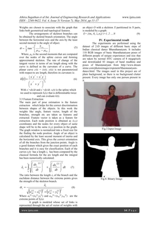
This paper presents a method for feature extraction from attributed relational graphs of upper body poses in Bharatanatyam dance, addressing challenges like background clutter and clothing diversity. It employs skeletonization techniques and geometrical feature extraction to facilitate accurate pose classification. Experimental evaluation is conducted using 110 images to demonstrate the robustness of the proposed approach in classifying dance poses.