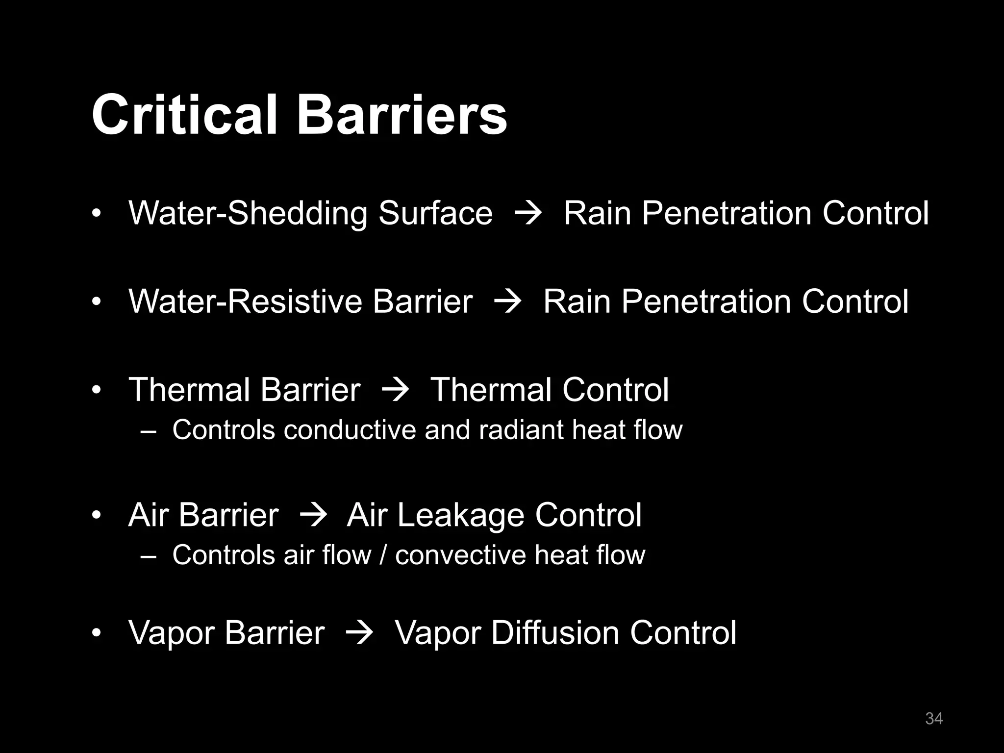
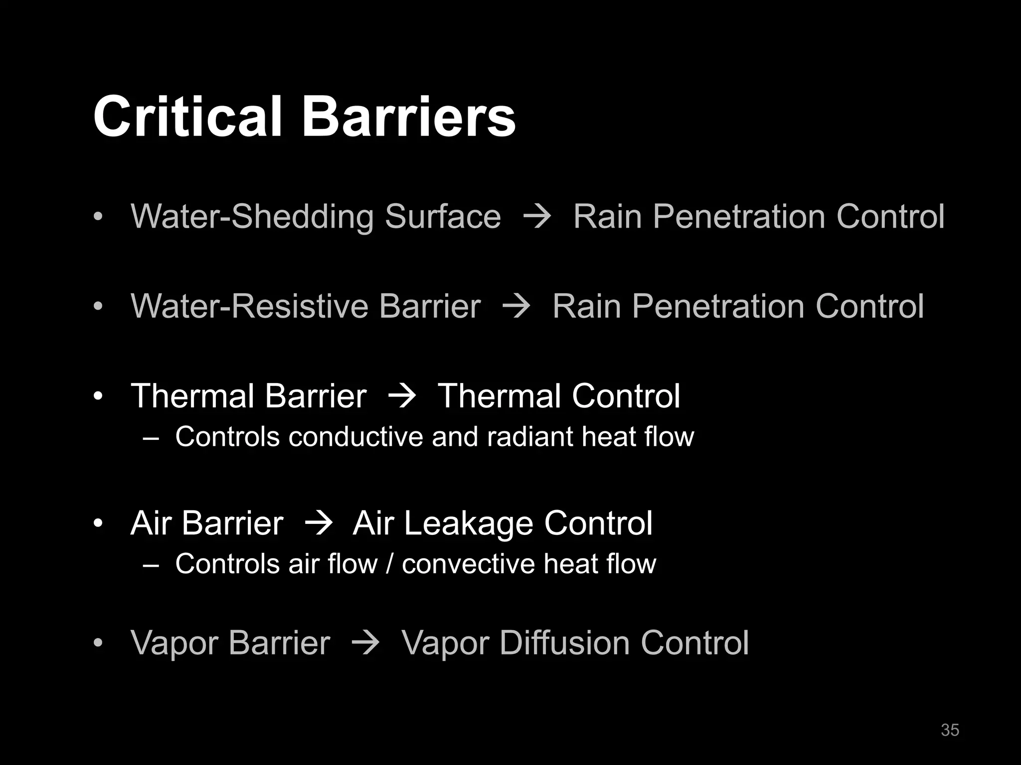
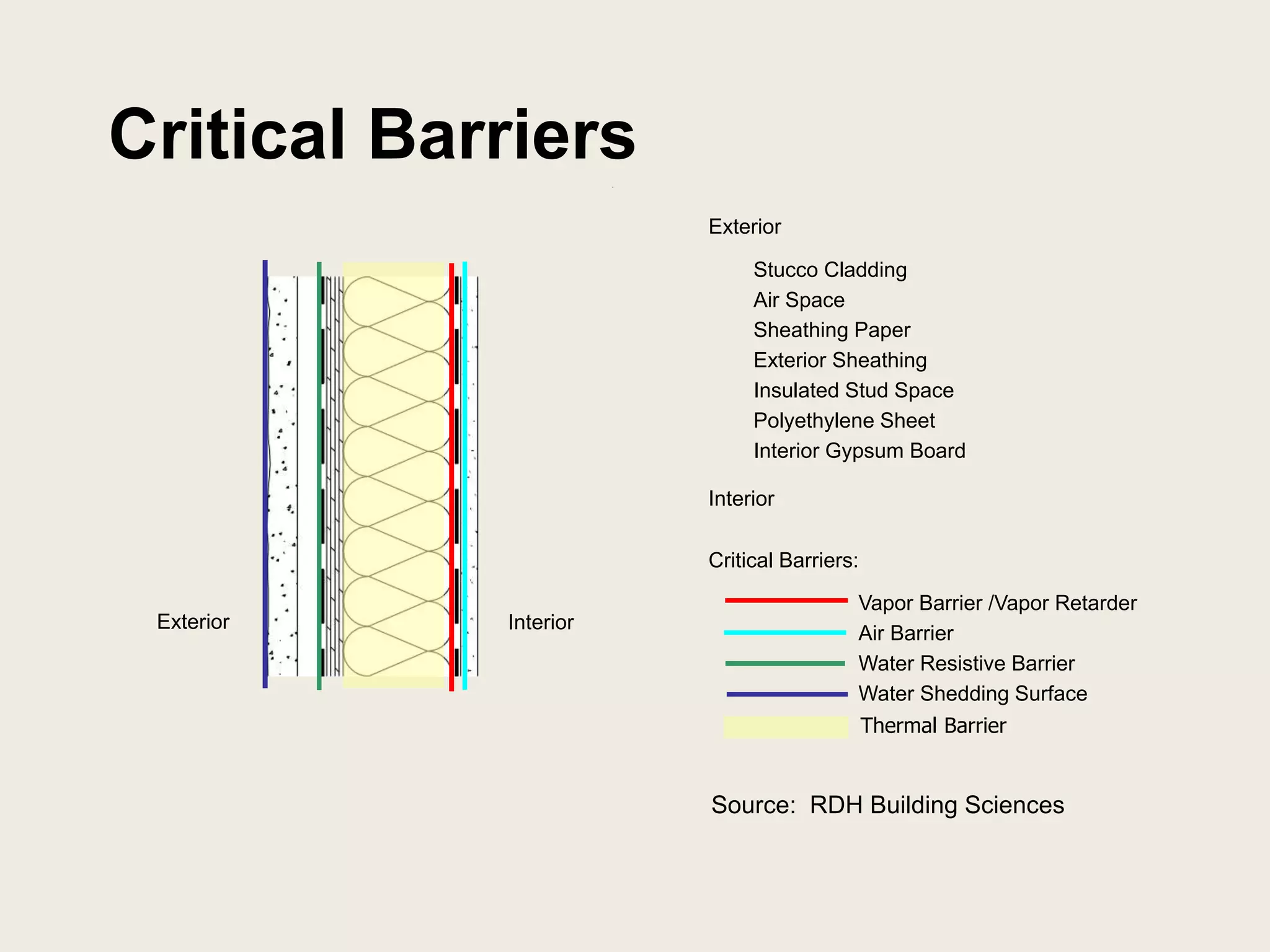
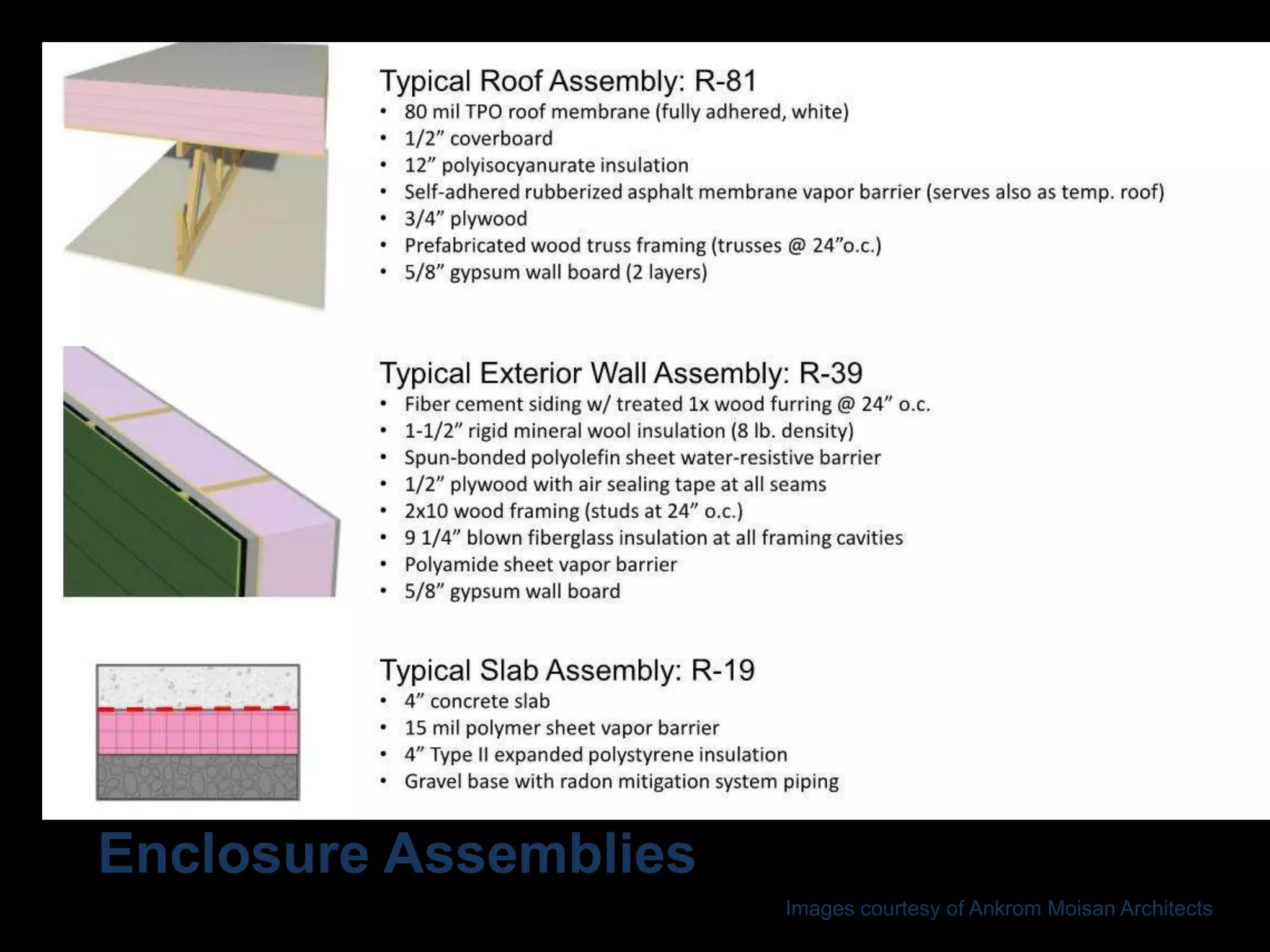
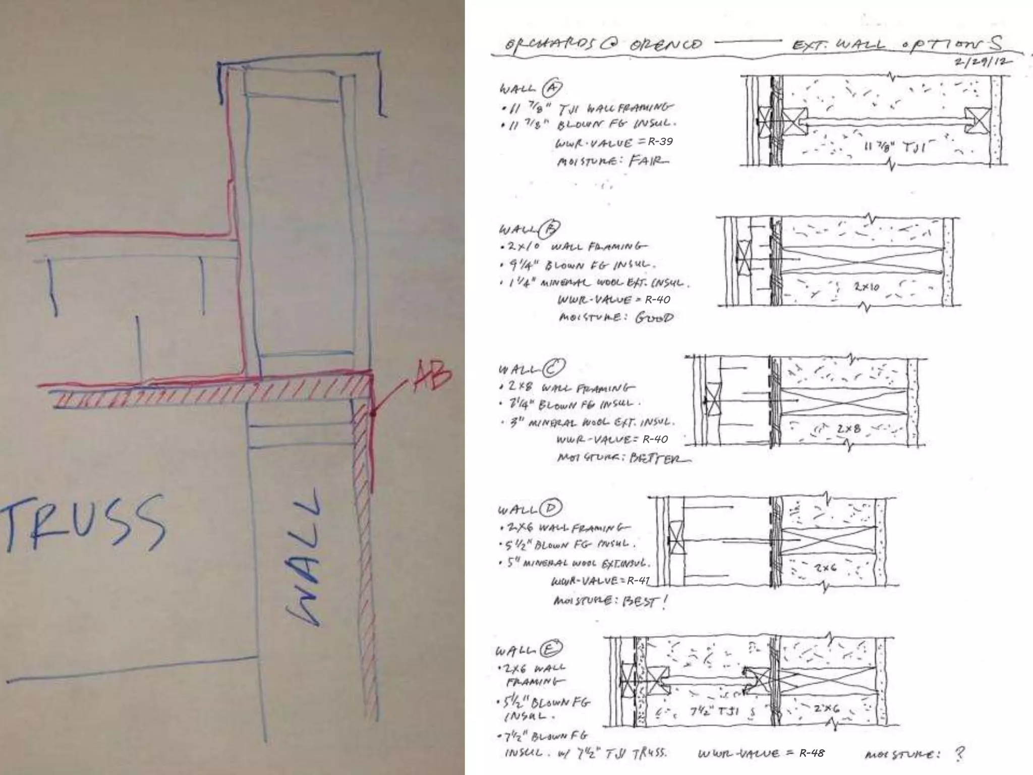
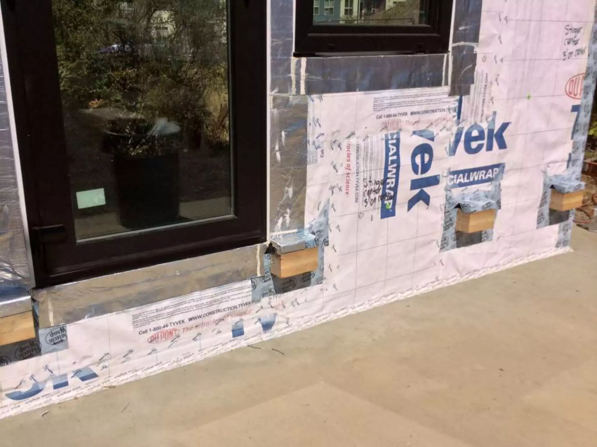
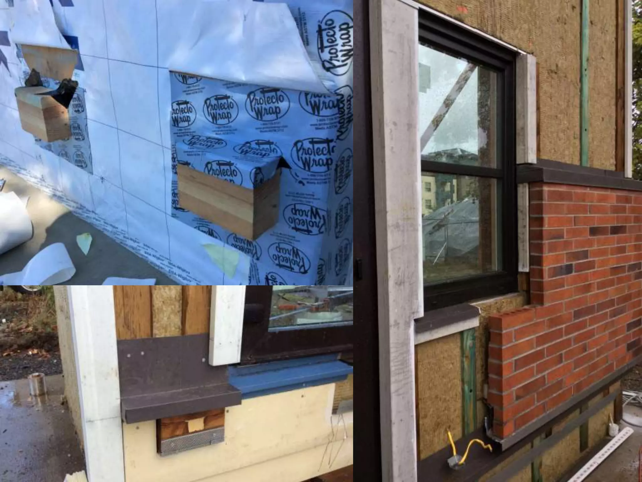
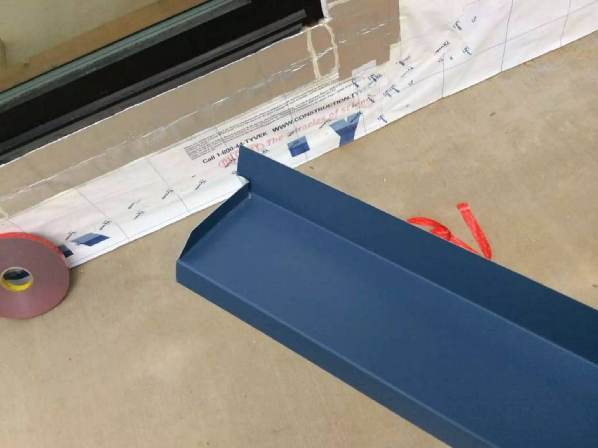
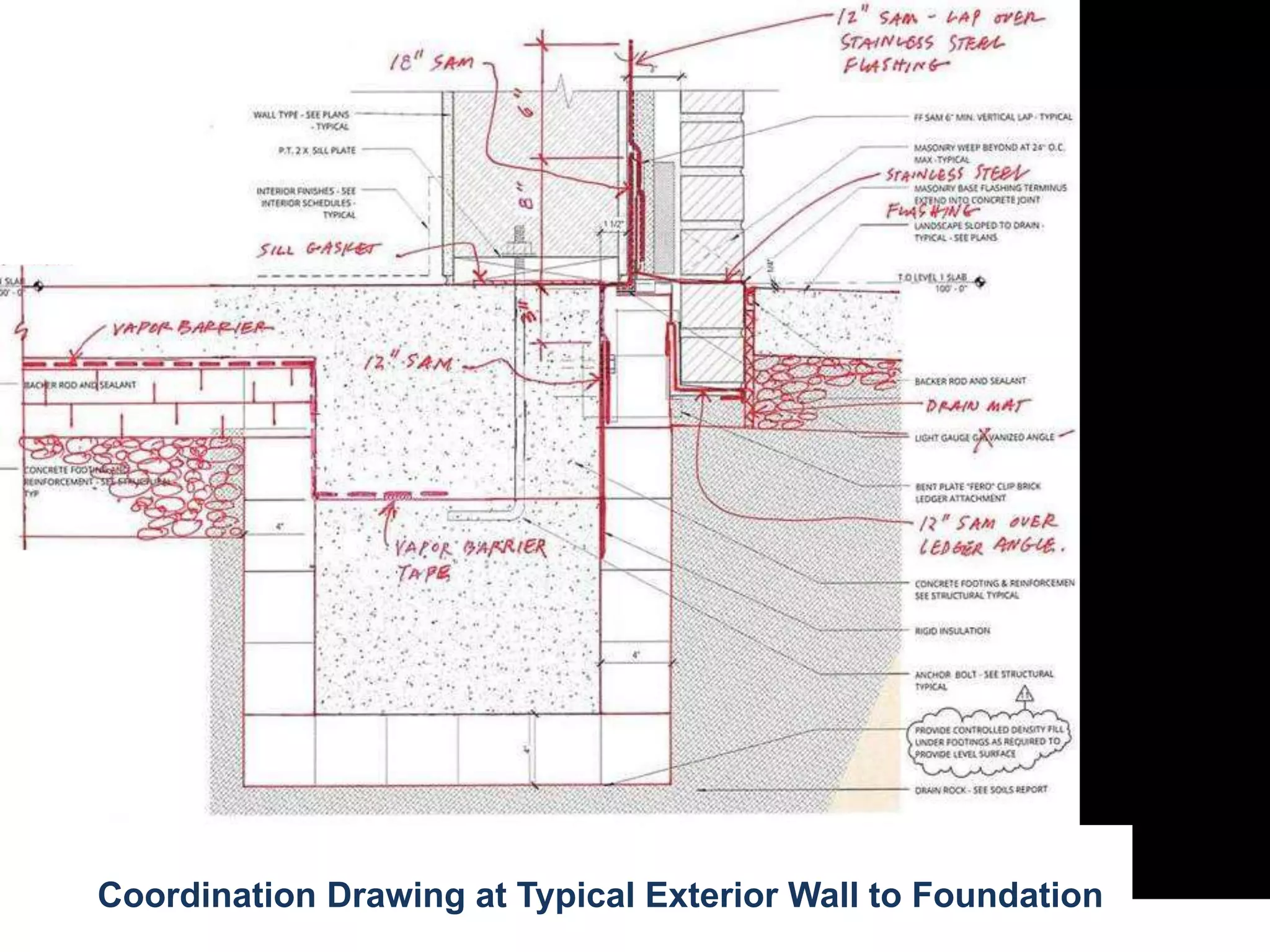
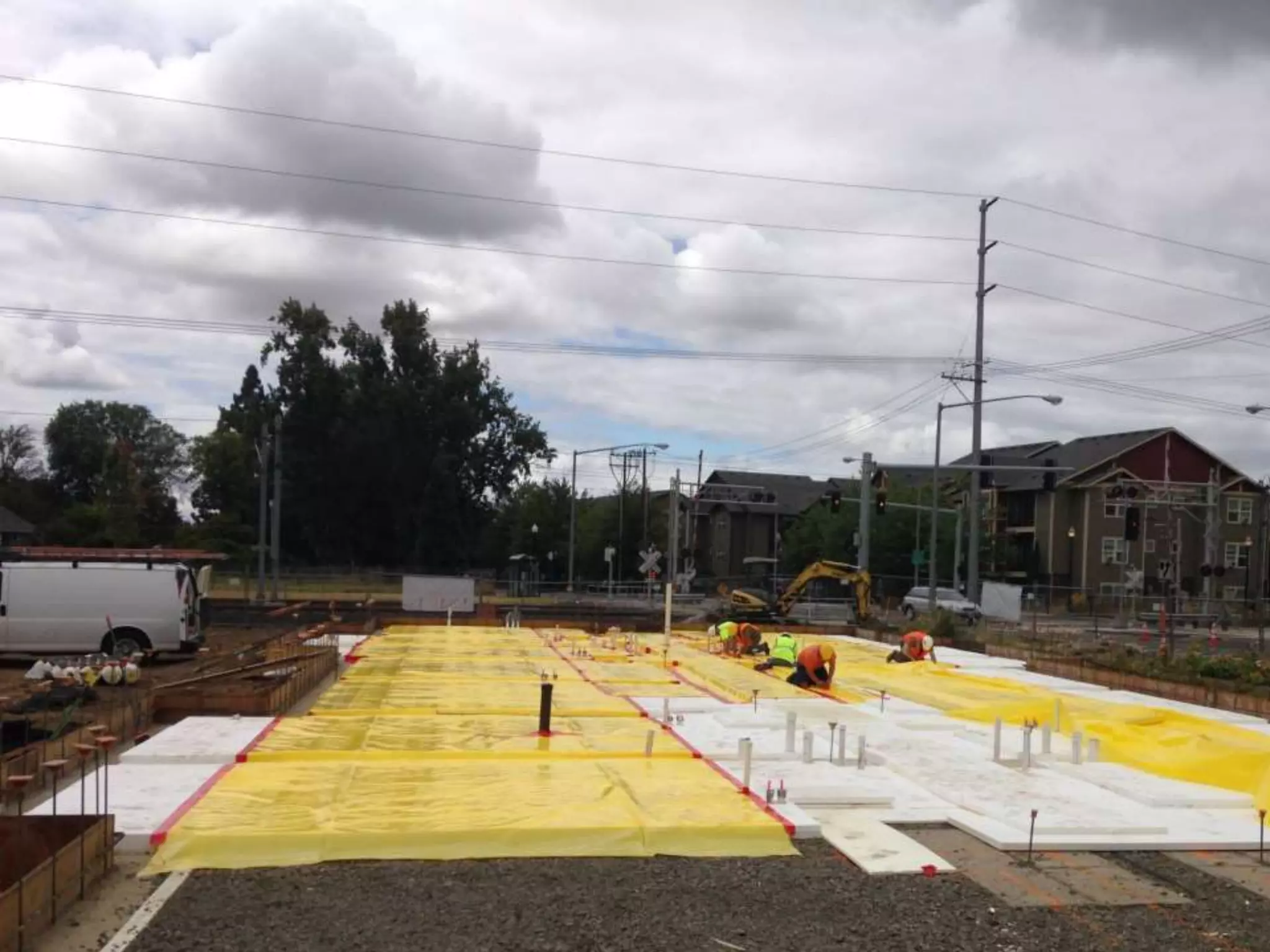
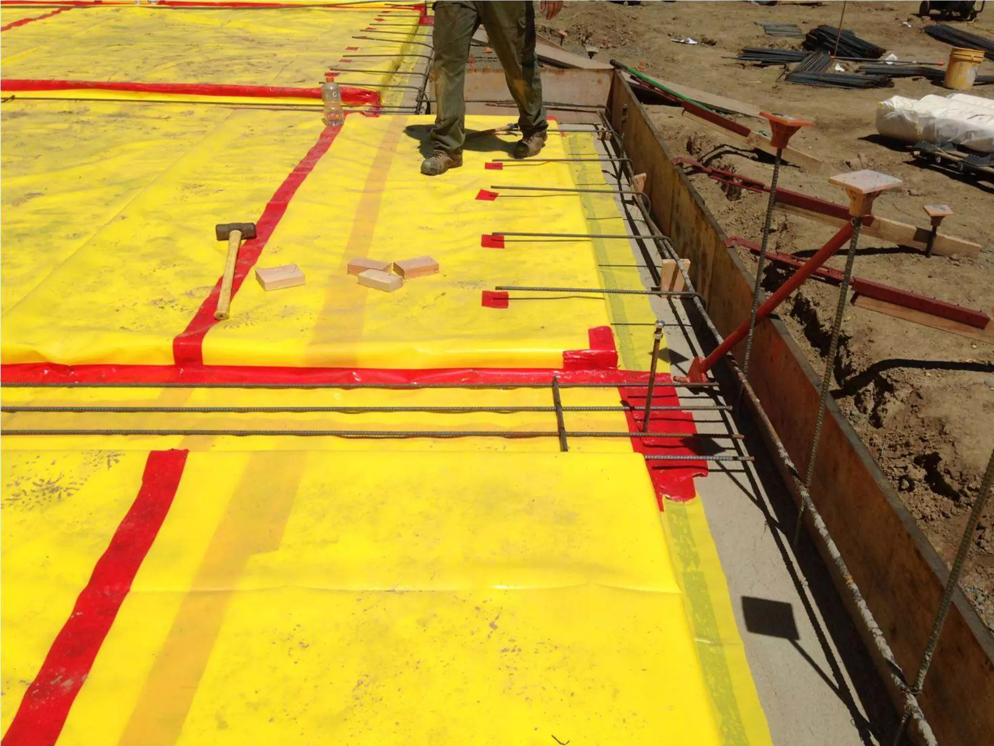
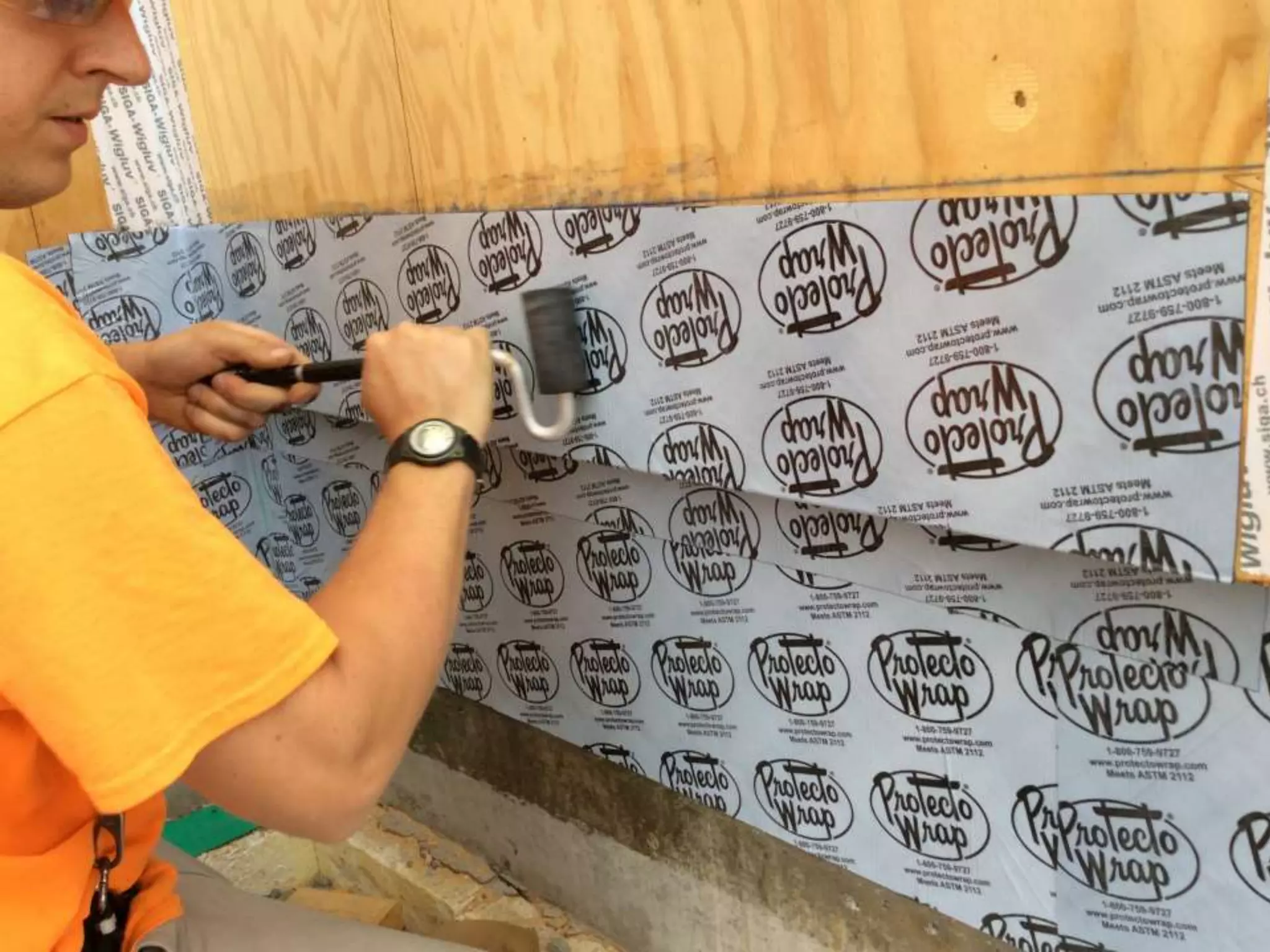
Enclosure Design
Training
AIA Portland
August 2016
Martin Houston
AIA, CSI, LEED AP
Walsh Construction Co.
CLEAResult
Energy Trust of Oregon
Enclosure Design Training
• The role of the Building Enclosure in the creation
of Low Energy Buildings
• Critical Barriers (Control Layers)
• The Thermal Control Layer
• The Air Control Layer
2
Presentation Outline
• Definitions
• Control Layers
• The Thermal Control Layer
• The Air Control Layer
3
Definition:
Water Vapor
Water in it’s gaseous state
4
Definition:
Water Vapor
Water in it’s gaseous state
5
Definition:
Water Vapor Diffusion
The process by which water vapor spreads or
moves through permeable materials caused
by a difference in water vapor pressure.
6
7
Definition:
Vapor Permeability
Permeability, rated in Perms, is a measure of
the rate of transfer of water vapor through a
material.
The higher the number, the easier it is to pass
water vapor through a material.
8
Vapor Permeability of
Standard Building Materials
1. Polyethylene .06
2. XPS Rigid 1
3. OSB 2
4. Plywood 3.5
5. EPS Rigid 3.5
6. 15# Felt 6
7. 2 PSJTX 11
8. Tyvek CW 23
9. Cat5 18
10. Vaproshield 50/212
9
Definition:
Condensation
Condensation is the change in the phase of
water from the gaseous phase into liquid
droplets or solid grains .
10
11
Definition:
Dew Point
• The dew point is the temperature to which a
given parcel of air must be cooled, at
constant barometric pressure, for water vapor
to condense into water.
12
13
14
Pop Quiz
1. How many of you know the difference
between an air barrier, a weather resistive
barrier and a vapor barrier?
2. How many materials do you need to have all
three in one wall
15
16
17
The Path to Low Energy Buildings
1
2
3
4
18
Basic Building
Design
Enclosure
MEP
On-site Renewable
Energy
The Path to Low Energy Buildings
1
2
3
4
19
Basic Building
Design
Enclosure
MEP
On-site Renewable
Energy
Load Reduction
The Path to Low Energy Buildings
1
2
3
4
20
Basic Building
Design
Enclosure
MEP
On-site Renewable
Energy
Load Reduction
Meeting loads as
efficiently and cleanly
as possible…
The Path to Low Energy Buildings
1
2
3
4
21
Basic Building
Design
Enclosure
MEP
On-site Renewable
Energy
Load Reduction
Enclosure – Key Attributes
• Insulation
• Airtightness
• Optimized
Glazing
22
Basic Building Design (BBD)
• Low energy building design should focus first
on a few basic building design concepts:
– Building size & shape
• As small as possible for the given program
• As compact as possible for the given program, relative to climatic
factors
– Building orientation
– Optimized glazing design
23
24
E-W Orientation = 5%-6% Reduction in Annual Energy Use
Dwg: Building Shape
25
All contain about 8 volume units-
What about surface area?
Enclosure Area to Volume Ratio
BBD
• Optimized Glazing Design – i.e. windows
sized, configured and oriented to optimize
daylighting, views and solar gain
– Window-to-wall ratio managed to avoid excessive
heat loss while allowing for daylighting and views
– Glazing systems designed to avoid excessive solar
gain – i.e. glass coatings, shadings, etc.
– Use well-insulated & airtight glazing systems
28
29
Window to Wall Ratio
Window-to-Wall Ratio
Assume: Window=U-0.33, Wall=R-15
Window-to-Wall Ratio: 10%
Window-to-Wall Ratio: 50%
Window-to-Wall Ratio: 90%
Critical Barriers
• Water-Shedding Surface  Rain Penetration Control
• Water-Resistive Barrier  Rain Penetration Control
• Thermal Barrier  Thermal Control
– Controls conductive and radiant heat flow
• Air Barrier  Air Leakage Control
– Controls air flow / convective heat flow
• Vapor Barrier  Vapor Diffusion Control
34
Critical Barriers
• Water-Shedding Surface  Rain Penetration Control
• Water-Resistive Barrier  Rain Penetration Control
• Thermal Barrier  Thermal Control
– Controls conductive and radiant heat flow
• Air Barrier  Air Leakage Control
– Controls air flow / convective heat flow
• Vapor Barrier  Vapor Diffusion Control
35
Critical Barriers
Thermal Barrier
Exterior
Stucco Cladding
Air Space
Sheathing Paper
Exterior Sheathing
Insulated Stud Space
Polyethylene Sheet
Interior Gypsum Board
Interior
Critical Barriers:
Vapor Barrier /Vapor Retarder
Air Barrier
Water Resistive Barrier
Water Shedding Surface
Exterior Interior
Source: RDH Building Sciences
Continuity – A Key Principle
• Continuous barriers are required to achieve
effective thermal and moisture performance
• Continuity of critical barriers must be
provided, not just at field areas, but also at
interface conditions
– Transitions
– Penetrations
– Terminations
37
VAPOR BARRIER
AIR BARRIER
WATER-RESISTIVE BARRIER
WATER SHEDDING SURFACE
AIR BARRIER
VAPOR BARRIER
WATER-RESISTIVE BARRIER
WATER SHEDDING SURFACE
Continuity
Continuity – A Key Principle
• Lack of continuity at critical barriers may result
in:
– Water leakage
– Air leakage
– Thermal bridging
– Condensation
39
Continuity – A Key Principle
• Lack of continuity at critical barriers may result
in:
– Water leakage
– Air leakage
– Thermal bridging
– Condensation
• Leading to:
– Poor energy performance
– Comfort problems
– Durability problems
40
Design of Critical Barriers
• Designer of the building enclosure should be
able to trace the continuity of each critical
barrier through the enclosure system
• Begin with building sections / wall sections
• Continue with foundation, wall and roof details
• Ensure continuity of all five barriers
41
Tracing the
Barriers
42
Thermal
Barrier (TB)
43
Water-shedding
Surface (WSS)
44
Water-resistive
Barrier (WRB)
45
Air Barrier
(AB)
46
Vapor Barrier
(VB)
47
Durability - A Key Principle
• If it doesn’t last very long, it’s not very
sustainable
• Selection and use of durable materials - suited
to the application / exposure - is critical
• Effective enclosure detailing for watertightness,
airtightness and thermal resistance is essential
to achieving both energy performance and
long term durability
48
The Air Barrier
• The air barrier is the system of materials that
controls air leakage / convective heat flow
through the building enclosure
• The air barrier is not one material but instead
is an integrated system of many different
materials/components
49
The Problem of Air Leakage
• Air leakage accounts for 20-40% of the heat
loss through building enclosures…
• Air leakage = higher energy costs
• Air leakage = larger carbon footprint
• Air leakage = reduced water penetration control
• Air leakage = increased condensation risk
• Air leakage = poor airflow control
– Impacts reliability of ventilation system design
50
51
Source: State of Wisconsin Minimium Requirements for the Building Envelope
Air Barrier - Definitions
• Air barriers are defined by their air permeance
• Air Barrier Association of America (ABAA) has
taken lead position in developing and
promulgating standards
• Now incorporated in many codes - including
WSEC
• “Materials”
– ≤ 0.04 cfm/sf @ 1.57 psf pressure differential
– ASTM E 2178, Standard Test Method for Air
Permeance of Building Materials
52
Air Barrier - Definitions
• “Assemblies”
– A collection of air barrier materials and air barrier
components assembled together in a specific
manner to create continuity (ABAA)
– ≤ 0.04 cfm/sf @ 1.57 psf
– ASTM E 2357, Standard Test Method for
Determining Air Leakage of Air Barrier Assemblies
53
Air Barrier - Definitions
• “System”
– An air barrier system is a system of building
assemblies within the building enclosure designed,
installed, and integrated in such a manner as to stop
the uncontrolled flow of air into and out of the building
enclosure (ABAA)
– A whole building air barrier is a system
– ≤ 0.40 cfm/sf @ 1.57 psf
– ASTM E 779, Standard Test Method for Determining
Air Leakage Rates by Fan Pressurization
– Alternate standard: ≤ 0.25 cfm/sf @ 1.57 psf (USACE)
54
Air Barrier - Materials
• Exterior cladding
• Sealants
• Flashings (membrane flashing, metal flashing)
• Windows
• Doors (poor AB)
• Housewraps (e.g. Tyvek)
• Wall membranes (e.g. “peel & stick”)
• Roof membranes
• Drywall
• Polyethylene sheet
55
Photo - Air Barrier
56
Air Barrier - Materials
• Material selection criteria includes:
– Air permeance
– Vapor permeance
– Water resistance (if serving as WRB also)
– Cost
– Constructability
– Availability
• Location / placement of air barrier relative to
insulation location is major determinant
57
Air Barrier - Approaches
• Interior Side
– Airtight Drywall Approach
– Sealed Polyethylene Approach
• Exterior Side
– Exterior Sheathing Approach
– Sheathing Membrane Approach (“housewrap”)
• Where cavity insulation approach is used
• Vapor permeable
58
Air Barrier - Approaches
• Exterior Side
– Exterior Sheathing Approach
– Sheathing Membrane Approach (“housewrap”)
• Where cavity insulation approach is used
• Vapor permeable
– Sheathing Membrane Approach (“peel & stick”)
• Where exterior insulation approach is used
• Vapor impermeable
61
Air Barrier - Approaches
• Exterior Side
– Exterior Sheathing Approach
– Sheathing Membrane Approach (“housewrap”)
• Where cavity insulation approach is used
• Vapor permeable
– Sheathing Membrane Approach (“peel & stick”)
• Where exterior insulation approach is used
• Vapor impermeable
– Sheathing Membrane Approach (fluid-applied)
• Vapor permeability dependent on whether cavity
insulation or exterior insulation approach is used
63
Air Barrier - Continuity
• To design and construct a complete air
barrier system for the building, continuity
must be provided at interfaces between all
materials and components…
• Easier said than done!
65
Air Barrier - Continuity
• Key Details for Air Barrier Continuity:
– Wall to foundation
– Roof to wall
– Floor lines
– Window and door perimeters
– Other penetrations
– Transitions between wall types
– Transitions between cladding materials
66
67
Airtightness & IAQ
• Mechanical ventilation becomes increasingly
important as building airtightness increases
• Effectiveness - and efficiency - of ventilation
system becomes more highly critical to
ensuring overall building performance,
including indoor air quality…
– Dedicated fresh air delivery to each space
– Controlled air flow between spaces
– Controlled ventilation rates
– Heat recovery from exhaust air
68
THE THERMAL BARRIER
Can you say “yellow light”?
70
THE THERMAL BARRIER
The Thermal Barrier
• The thermal barrier is the system of materials
that controls conductive and radiant heat flow
through the building enclosure
• Insulation - yes - but many other materials
too…
71
Thermal Barrier Problems
• Thermal Bridges
• Insulation Material Selection
• Insulation Installation Defects
72
73
Get your thermal bridge on
74
Thermal Bridging
Thermal Barrier Problems
• Thermal Bridges
• Insulation Material Selection
• Insulation Installation Defects
• Glazing Assemblies
75
76
77
Thermal Barrier Problems
• Thermal Bridges
• Insulation Material Selection
• Insulation Installation Defects
• Glazing Assemblies
78
79
Thermal Bridges
• Exterior Wall Framing Members
– Light gauge steel framing
– Wood framing
80
R-Value Comparison
81
Source: Robert Bombino
Photo - Light Steel Frame Walls
82
83
Thermal Bridges
• Exterior Wall Framing Members
– Light gauge steel framing
– Wood framing
• Regions of Framing “Build-up”
– Exterior Wall Openings (e.g. headers, posts)
– Exterior Wall Corners
– Exterior Wall to Floor Intersections
– Exterior Wall to Roof Intersections
84
Photo: Not so advanced framing…
Other Thermal Bridges
• Window Frames (Aluminum & Steel)
• Metal Subframing at Cladding Systems
• Steel Ledger Angles at Cladding Systems
• Projecting Slab Edges (Concrete)
• Large Structural Framing Members (Steel)
86
Drawing – Straube report
87
Drawing – Straube report
88
Drawing – Straube report
89
Image courtesy of Mike Williams
90
91
92
Design Overview
Photo Credit: Casey Braunger
Aerial View from South
Image courtesy of Ankrom Moisan Architects
First Floor Plan
Image courtesy of Ankrom Moisan Architects
Enclosure Assemblies
Images courtesy of Ankrom Moisan Architects
Shading Elements
Balconies
Eyebrows
Image courtesy of William Wilson Architects
HVAC Design
• Highly iterative process
– Design work  modeling work  costing analysis 
constructability review
– Repeat…
• Bidding / procurement
• Coordinating the work…
HVAC Design
• Highly iterative process
– Design work  modeling work  costing analysis 
constructability review
– Repeat…
• Bidding / procurement
• Coordinating the work…
ERV
HEAT
PUMP
Heating & Partial Cooling
Image courtesy of PAE Consulting Engineers
HVAC Design
• Highly iterative process
– Design work  modeling work  costing analysis 
constructability review
– Repeat…
• Bidding / procurement
• Coordinating the work…
Mechanical Penthouse
HVAC Design
• 3 HRV Zones
• Cook ERV serves each zone
HVAC Design
• Continuous 50cfm
supply air per
bedroom
• Continuous
exhaust at kitchen
and bath
• Electric cove
heater in living
room for user
control & backup
heat
- Estimated at 20% of building heating
load
• No active cooling at apartments
Image courtesy of PAE Consulting Engineers
R-39
R-40
R-40
R-41
R-48
Coordination Drawing at Typical Exterior Wall to Foundation
Coordination Drawing at Typical Exterior Wall to Roof
Balcony details
Balcony details
Building enclosure design presentation 1

Building enclosure design presentation 1

  • 1.
    Enclosure Design Training AIA Portland August2016 Martin Houston AIA, CSI, LEED AP Walsh Construction Co. CLEAResult Energy Trust of Oregon
  • 2.
    Enclosure Design Training •The role of the Building Enclosure in the creation of Low Energy Buildings • Critical Barriers (Control Layers) • The Thermal Control Layer • The Air Control Layer 2
  • 3.
    Presentation Outline • Definitions •Control Layers • The Thermal Control Layer • The Air Control Layer 3
  • 4.
    Definition: Water Vapor Water init’s gaseous state 4
  • 5.
    Definition: Water Vapor Water init’s gaseous state 5
  • 6.
    Definition: Water Vapor Diffusion Theprocess by which water vapor spreads or moves through permeable materials caused by a difference in water vapor pressure. 6
  • 7.
  • 8.
    Definition: Vapor Permeability Permeability, ratedin Perms, is a measure of the rate of transfer of water vapor through a material. The higher the number, the easier it is to pass water vapor through a material. 8
  • 9.
    Vapor Permeability of StandardBuilding Materials 1. Polyethylene .06 2. XPS Rigid 1 3. OSB 2 4. Plywood 3.5 5. EPS Rigid 3.5 6. 15# Felt 6 7. 2 PSJTX 11 8. Tyvek CW 23 9. Cat5 18 10. Vaproshield 50/212 9
  • 10.
    Definition: Condensation Condensation is thechange in the phase of water from the gaseous phase into liquid droplets or solid grains . 10
  • 11.
  • 12.
    Definition: Dew Point • Thedew point is the temperature to which a given parcel of air must be cooled, at constant barometric pressure, for water vapor to condense into water. 12
  • 13.
  • 14.
  • 15.
    Pop Quiz 1. Howmany of you know the difference between an air barrier, a weather resistive barrier and a vapor barrier? 2. How many materials do you need to have all three in one wall 15
  • 16.
  • 17.
  • 18.
    The Path toLow Energy Buildings 1 2 3 4 18 Basic Building Design Enclosure MEP On-site Renewable Energy
  • 19.
    The Path toLow Energy Buildings 1 2 3 4 19 Basic Building Design Enclosure MEP On-site Renewable Energy Load Reduction
  • 20.
    The Path toLow Energy Buildings 1 2 3 4 20 Basic Building Design Enclosure MEP On-site Renewable Energy Load Reduction Meeting loads as efficiently and cleanly as possible…
  • 21.
    The Path toLow Energy Buildings 1 2 3 4 21 Basic Building Design Enclosure MEP On-site Renewable Energy Load Reduction
  • 22.
    Enclosure – KeyAttributes • Insulation • Airtightness • Optimized Glazing 22
  • 23.
    Basic Building Design(BBD) • Low energy building design should focus first on a few basic building design concepts: – Building size & shape • As small as possible for the given program • As compact as possible for the given program, relative to climatic factors – Building orientation – Optimized glazing design 23
  • 24.
    24 E-W Orientation =5%-6% Reduction in Annual Energy Use
  • 25.
    Dwg: Building Shape 25 Allcontain about 8 volume units- What about surface area?
  • 26.
    Enclosure Area toVolume Ratio
  • 27.
    Enclosure Area toVolume Ratio
  • 28.
    BBD • Optimized GlazingDesign – i.e. windows sized, configured and oriented to optimize daylighting, views and solar gain – Window-to-wall ratio managed to avoid excessive heat loss while allowing for daylighting and views – Glazing systems designed to avoid excessive solar gain – i.e. glass coatings, shadings, etc. – Use well-insulated & airtight glazing systems 28
  • 29.
  • 30.
  • 31.
  • 32.
  • 33.
  • 34.
    Critical Barriers • Water-SheddingSurface  Rain Penetration Control • Water-Resistive Barrier  Rain Penetration Control • Thermal Barrier  Thermal Control – Controls conductive and radiant heat flow • Air Barrier  Air Leakage Control – Controls air flow / convective heat flow • Vapor Barrier  Vapor Diffusion Control 34
  • 35.
    Critical Barriers • Water-SheddingSurface  Rain Penetration Control • Water-Resistive Barrier  Rain Penetration Control • Thermal Barrier  Thermal Control – Controls conductive and radiant heat flow • Air Barrier  Air Leakage Control – Controls air flow / convective heat flow • Vapor Barrier  Vapor Diffusion Control 35
  • 36.
    Critical Barriers Thermal Barrier Exterior StuccoCladding Air Space Sheathing Paper Exterior Sheathing Insulated Stud Space Polyethylene Sheet Interior Gypsum Board Interior Critical Barriers: Vapor Barrier /Vapor Retarder Air Barrier Water Resistive Barrier Water Shedding Surface Exterior Interior Source: RDH Building Sciences
  • 37.
    Continuity – AKey Principle • Continuous barriers are required to achieve effective thermal and moisture performance • Continuity of critical barriers must be provided, not just at field areas, but also at interface conditions – Transitions – Penetrations – Terminations 37
  • 38.
    VAPOR BARRIER AIR BARRIER WATER-RESISTIVEBARRIER WATER SHEDDING SURFACE AIR BARRIER VAPOR BARRIER WATER-RESISTIVE BARRIER WATER SHEDDING SURFACE Continuity
  • 39.
    Continuity – AKey Principle • Lack of continuity at critical barriers may result in: – Water leakage – Air leakage – Thermal bridging – Condensation 39
  • 40.
    Continuity – AKey Principle • Lack of continuity at critical barriers may result in: – Water leakage – Air leakage – Thermal bridging – Condensation • Leading to: – Poor energy performance – Comfort problems – Durability problems 40
  • 41.
    Design of CriticalBarriers • Designer of the building enclosure should be able to trace the continuity of each critical barrier through the enclosure system • Begin with building sections / wall sections • Continue with foundation, wall and roof details • Ensure continuity of all five barriers 41
  • 42.
  • 43.
  • 44.
  • 45.
  • 46.
  • 47.
  • 48.
    Durability - AKey Principle • If it doesn’t last very long, it’s not very sustainable • Selection and use of durable materials - suited to the application / exposure - is critical • Effective enclosure detailing for watertightness, airtightness and thermal resistance is essential to achieving both energy performance and long term durability 48
  • 49.
    The Air Barrier •The air barrier is the system of materials that controls air leakage / convective heat flow through the building enclosure • The air barrier is not one material but instead is an integrated system of many different materials/components 49
  • 50.
    The Problem ofAir Leakage • Air leakage accounts for 20-40% of the heat loss through building enclosures… • Air leakage = higher energy costs • Air leakage = larger carbon footprint • Air leakage = reduced water penetration control • Air leakage = increased condensation risk • Air leakage = poor airflow control – Impacts reliability of ventilation system design 50
  • 51.
    51 Source: State ofWisconsin Minimium Requirements for the Building Envelope
  • 52.
    Air Barrier -Definitions • Air barriers are defined by their air permeance • Air Barrier Association of America (ABAA) has taken lead position in developing and promulgating standards • Now incorporated in many codes - including WSEC • “Materials” – ≤ 0.04 cfm/sf @ 1.57 psf pressure differential – ASTM E 2178, Standard Test Method for Air Permeance of Building Materials 52
  • 53.
    Air Barrier -Definitions • “Assemblies” – A collection of air barrier materials and air barrier components assembled together in a specific manner to create continuity (ABAA) – ≤ 0.04 cfm/sf @ 1.57 psf – ASTM E 2357, Standard Test Method for Determining Air Leakage of Air Barrier Assemblies 53
  • 54.
    Air Barrier -Definitions • “System” – An air barrier system is a system of building assemblies within the building enclosure designed, installed, and integrated in such a manner as to stop the uncontrolled flow of air into and out of the building enclosure (ABAA) – A whole building air barrier is a system – ≤ 0.40 cfm/sf @ 1.57 psf – ASTM E 779, Standard Test Method for Determining Air Leakage Rates by Fan Pressurization – Alternate standard: ≤ 0.25 cfm/sf @ 1.57 psf (USACE) 54
  • 55.
    Air Barrier -Materials • Exterior cladding • Sealants • Flashings (membrane flashing, metal flashing) • Windows • Doors (poor AB) • Housewraps (e.g. Tyvek) • Wall membranes (e.g. “peel & stick”) • Roof membranes • Drywall • Polyethylene sheet 55
  • 56.
    Photo - AirBarrier 56
  • 57.
    Air Barrier -Materials • Material selection criteria includes: – Air permeance – Vapor permeance – Water resistance (if serving as WRB also) – Cost – Constructability – Availability • Location / placement of air barrier relative to insulation location is major determinant 57
  • 58.
    Air Barrier -Approaches • Interior Side – Airtight Drywall Approach – Sealed Polyethylene Approach • Exterior Side – Exterior Sheathing Approach – Sheathing Membrane Approach (“housewrap”) • Where cavity insulation approach is used • Vapor permeable 58
  • 61.
    Air Barrier -Approaches • Exterior Side – Exterior Sheathing Approach – Sheathing Membrane Approach (“housewrap”) • Where cavity insulation approach is used • Vapor permeable – Sheathing Membrane Approach (“peel & stick”) • Where exterior insulation approach is used • Vapor impermeable 61
  • 63.
    Air Barrier -Approaches • Exterior Side – Exterior Sheathing Approach – Sheathing Membrane Approach (“housewrap”) • Where cavity insulation approach is used • Vapor permeable – Sheathing Membrane Approach (“peel & stick”) • Where exterior insulation approach is used • Vapor impermeable – Sheathing Membrane Approach (fluid-applied) • Vapor permeability dependent on whether cavity insulation or exterior insulation approach is used 63
  • 65.
    Air Barrier -Continuity • To design and construct a complete air barrier system for the building, continuity must be provided at interfaces between all materials and components… • Easier said than done! 65
  • 66.
    Air Barrier -Continuity • Key Details for Air Barrier Continuity: – Wall to foundation – Roof to wall – Floor lines – Window and door perimeters – Other penetrations – Transitions between wall types – Transitions between cladding materials 66
  • 67.
  • 68.
    Airtightness & IAQ •Mechanical ventilation becomes increasingly important as building airtightness increases • Effectiveness - and efficiency - of ventilation system becomes more highly critical to ensuring overall building performance, including indoor air quality… – Dedicated fresh air delivery to each space – Controlled air flow between spaces – Controlled ventilation rates – Heat recovery from exhaust air 68
  • 69.
    THE THERMAL BARRIER Canyou say “yellow light”?
  • 70.
  • 71.
    The Thermal Barrier •The thermal barrier is the system of materials that controls conductive and radiant heat flow through the building enclosure • Insulation - yes - but many other materials too… 71
  • 72.
    Thermal Barrier Problems •Thermal Bridges • Insulation Material Selection • Insulation Installation Defects 72
  • 73.
  • 74.
  • 75.
    Thermal Barrier Problems •Thermal Bridges • Insulation Material Selection • Insulation Installation Defects • Glazing Assemblies 75
  • 76.
  • 77.
  • 78.
    Thermal Barrier Problems •Thermal Bridges • Insulation Material Selection • Insulation Installation Defects • Glazing Assemblies 78
  • 79.
  • 80.
    Thermal Bridges • ExteriorWall Framing Members – Light gauge steel framing – Wood framing 80
  • 81.
  • 82.
    Photo - LightSteel Frame Walls 82
  • 83.
  • 84.
    Thermal Bridges • ExteriorWall Framing Members – Light gauge steel framing – Wood framing • Regions of Framing “Build-up” – Exterior Wall Openings (e.g. headers, posts) – Exterior Wall Corners – Exterior Wall to Floor Intersections – Exterior Wall to Roof Intersections 84
  • 85.
    Photo: Not soadvanced framing…
  • 86.
    Other Thermal Bridges •Window Frames (Aluminum & Steel) • Metal Subframing at Cladding Systems • Steel Ledger Angles at Cladding Systems • Projecting Slab Edges (Concrete) • Large Structural Framing Members (Steel) 86
  • 87.
  • 88.
  • 89.
    Drawing – Straubereport 89 Image courtesy of Mike Williams
  • 90.
  • 91.
  • 92.
  • 93.
  • 94.
    Aerial View fromSouth Image courtesy of Ankrom Moisan Architects
  • 95.
    First Floor Plan Imagecourtesy of Ankrom Moisan Architects
  • 96.
    Enclosure Assemblies Images courtesyof Ankrom Moisan Architects
  • 97.
  • 98.
    HVAC Design • Highlyiterative process – Design work  modeling work  costing analysis  constructability review – Repeat… • Bidding / procurement • Coordinating the work…
  • 99.
    HVAC Design • Highlyiterative process – Design work  modeling work  costing analysis  constructability review – Repeat… • Bidding / procurement • Coordinating the work… ERV HEAT PUMP Heating & Partial Cooling Image courtesy of PAE Consulting Engineers
  • 100.
    HVAC Design • Highlyiterative process – Design work  modeling work  costing analysis  constructability review – Repeat… • Bidding / procurement • Coordinating the work… Mechanical Penthouse
  • 101.
    HVAC Design • 3HRV Zones • Cook ERV serves each zone
  • 102.
    HVAC Design • Continuous50cfm supply air per bedroom • Continuous exhaust at kitchen and bath • Electric cove heater in living room for user control & backup heat - Estimated at 20% of building heating load • No active cooling at apartments Image courtesy of PAE Consulting Engineers
  • 103.
  • 107.
    Coordination Drawing atTypical Exterior Wall to Foundation
  • 112.
    Coordination Drawing atTypical Exterior Wall to Roof
  • 123.
  • 124.