SlideShare a Scribd company logo
Massimiliano & Doriana Fuksas
San Paolo Parish Complex
Introduction
Structural Focus
Systems Function
Structural Systems: Walls
Structural Systems: Roof
Model-making Process
Concept
Model Analysis
Structure Analysis
Conclusion
pg 4 ...............................................................................................................
pg 6 .......................................................................................................
pg 7 .............................................................................................
pg 8 ...........................................................................
pg 10 .........................................................................
pg 11 .......................................................................................
pg 14 .............................................................................
pg 17 ................................................................................................
pg 19 ........................................................................................
pg 20 .......................................................................................................
CONCEPT
pg 4
“The suspension of a volume
within another. Seeing through
concrete heaven, from outside,
to inside, to outside”
-Massimiliano Fuksas
“For the achievement of the architect
was inspired by the vertical design
of the church, in keeping with
the liturgical celebration of the Mass
and the intention was to redefine
the concept of a link
between heaven and earth
through the momentum upward.”
-Bellaumbria.net
pg 5
Site: Via del Roccolo 30, 06034 Foligno PG, Italy
Project Year: 2001-2009
Client: Italian Episcopal Conference - Diocesi of Foligno
Total area: 20,690 sqm
Building area: 610 sqm
Parish complex: 1,300 sqm
symbol of rebirth - the San Paolo church designed by
Massimiliano and Doriana Fuksas in 2009 was introduced
after a devastating earthquake locally. It emerged as the winning
entry for a competition - proposed for a developing town named
Foligno, against a gorgeous mountainous backdrop in Italy. Til
present, it functions to serve the San Paolo Parish’s Catholic
congregation.
The 25 metres tall, monolithic, box of a building stands out in
strong contrast against the organic backdrop of huge mountains
and amongst quaint residential buildings, yet, it manages to blend
in with its seemingly modernist neighbours.
Cladded in light grey, the concrete and steel church features
distinctive “light canons” on its East and West facades. These
structural openings ingeniously control and direct sunlight into the
building. To the South, a gentle slope leads to a broad band of clear
glass, with a cross marking the point of entry. The interior is a box
within a box, position centrally and unified by a ceiling with three
rectangular skylights which alludes to the holy trinity. The interior
“box” is made of lightweight concrete on a steel frame, suspended
from structural beams in the roof to hover above the floor at the
height of 3 metres.
As if personifying the paradox of faith, the San Paolo church is
really a complex creation, in spite of staggering simplicity observed
at first sight.
Factual reference: http://www.theplan.it/J/index.php?option=com_content&view=article&id=88
2:complesso-parrocchiale-san-paolo&Itemid=367&lang=en
A
pg 6
STRUCTURAL FOCUS
ROOF
WALLS
pg 7
STRUCTURAL SYSTEM: WALLS
Exterior Wall
Materials:
- The structure of the external wall
consists of reinforced concrete columns
with reinforced concrete beams forming
the frames.
- Styrofoam panels form the walls with
reinforced concrete layer sandwiching
the Styrofoam panels.
- The concrete layers are linked to each
other with metal elements.
Holes for
metal ties
Styrofoam
Panel
Reinforced
Concrete layer
Column
Beam
Holes for metal
ties
Reinforced
Concrete layer
Styrofoam Panel
Column
Beam
pg 8
Interior Wall
STRUCTURAL SYSTEM: WALLS
Secondary
roof beam
Steel Structure
Plaster Board
Bracket on beam to
connect to the steel
structure
Materials:
- The internal walls are supported by steel
structure which connects to the roof.
- Plaster boards are installed to form the walls.
Secondary roof
beam
Plaster Board
Steel structure
Bracket on beam to
connect to the steel
structure
pg 9
STRUCTURAL SYSTEM: ROOF
Secondary
roof beam
Main roof
beam
Roof truss
Materials:
- The roof consists of 5 main beams and a series
of secondary beams. The secondary beams
support the “hung walls”.
- The internal elements of the roof are formed
by trusses.
The roof is finished with a reinforced concrete
slab
Main roof beam
Roof truss
Secondary roof
beam
pg 10
SYSTEMS FUNCTION
Roof
External wall
Internal wall
Light shafts
- Barrier to harsh weather
- Windbreaker
- Provides thermal
insulation
- Waterproofs building
interior
- Control excessive lighting
- Hold up roof beams
- Isolate space for privacy
- Provides added insulation
- Control and direct sunlight
into the main space
- Creates an “upward
momentum”
- Define spatial hierarchy
Barrier to harsh cold weather
- Windbreaker
- Provides thermal insulation
- Waterproofs building interior (Direct rainwater away)
- Control excessive lighting
pg 10
MODEL-MAKING PROCESS
The walls
pg 12
MODEL-MAKING PROCESS
The I-beams and trusses
pg 13
MODEL-MAKING PROCESS
The walls and roof
pg 14
MODEL-MAKING PROCESS
The skylights
pg 15
MODEL-MAKING PROCESS
The mock-up model The final model
pg 16
MODEL ANALYSIS
Materials:
Failure - Concrete (cement+sand+water)
Initially, concrete was used for the construction of wall. However the it was predicted that the heavy load of concrete was
not practical due to the large area of walls needed to be built. Other than that, there wereforeseen difficulties in controlling
the thickness of the internal concrete walls. At the chosen scale, those walls would measure 0.2cm thick which might lead
to severe concrete cracks.
Success – Chipboard
Instead of using concrete, chipboard was used to represent the concrete material as it is lighter in weight and could
acheive the appropriate thickness needed without compromising in structural stability.
Concrete Concrete Chipboard
pg 17
MODEL ANALYSIS
Construction of light shafts:
Slanted light shafts penetrating through the outer and inner walls are angled, therefore, their openings vary in position
on both walls. This resulted in a tricky situation as the angles are varied and unknown to the team. Nevertheless, an
ingenious solution was found by one of the teammates thereafter.
The location of openings on both walls were figured out by calculating ratios with the formula below:
d1/d2 = D1/D2
pg 18
STRUCTURE ANALYSIS
Load distribution:
pg 19
CONCLUSION
The project has been a success despite several bumps faced along
the way. Much knowledge with regards to solid building construction
has been gained by the team. Many thanks to Ms Sufina who was
supportive of the project and provided effective advice.
pg 20
PRODUCED BY:
Choo Ai Lin [0317253]; Hiew Yen Nee [0314212]; Kian Soon Jean [0314978];
Leong Carmen [0314953]; Liew Hui En [0314920]; Tan Heng Yee [0314941]; Yong Seh Li [0314345]
Building Construction 2 (ARC 2513)
Project 2 - Solid Construction

More Related Content

Similar to Building Construction 2: Project 2 Fuksas booklet

Curtain wall%2 f facade system
Curtain wall%2 f facade systemCurtain wall%2 f facade system
Curtain wall%2 f facade system
ahmong4
 
Portfolio_Dylan Russ
Portfolio_Dylan RussPortfolio_Dylan Russ
Portfolio_Dylan Russ
Dylan Russ
 

Similar to Building Construction 2: Project 2 Fuksas booklet (20)

Building Technology I - Project 2
Building Technology I - Project 2Building Technology I - Project 2
Building Technology I - Project 2
 
Building Technology 1 "Construction Solutions"
Building Technology 1 "Construction Solutions"Building Technology 1 "Construction Solutions"
Building Technology 1 "Construction Solutions"
 
Building Technology project 02
Building Technology project 02Building Technology project 02
Building Technology project 02
 
Facades and envelopes
Facades and envelopesFacades and envelopes
Facades and envelopes
 
Btech 1, 2
Btech 1, 2Btech 1, 2
Btech 1, 2
 
Building construction 02
Building construction 02Building construction 02
Building construction 02
 
Building Construction 02 (Project1)
Building Construction 02 (Project1)Building Construction 02 (Project1)
Building Construction 02 (Project1)
 
A3 report
A3 reportA3 report
A3 report
 
PROJECT 2: CONSTRUCTION SOLUTIONS
PROJECT 2: CONSTRUCTION SOLUTIONSPROJECT 2: CONSTRUCTION SOLUTIONS
PROJECT 2: CONSTRUCTION SOLUTIONS
 
Btechfinal
BtechfinalBtechfinal
Btechfinal
 
Curtain wall%2 f facade system
Curtain wall%2 f facade systemCurtain wall%2 f facade system
Curtain wall%2 f facade system
 
Curtain wall presentation slides
Curtain wall presentation slidesCurtain wall presentation slides
Curtain wall presentation slides
 
Case Study: Catenary Structures
Case Study: Catenary StructuresCase Study: Catenary Structures
Case Study: Catenary Structures
 
B tech project 2
B tech project 2B tech project 2
B tech project 2
 
BMC II 03 GLASS.pptx
BMC II 03 GLASS.pptxBMC II 03 GLASS.pptx
BMC II 03 GLASS.pptx
 
Portal Frame Construction & Pre Engineered Building System
Portal Frame Construction & Pre Engineered Building SystemPortal Frame Construction & Pre Engineered Building System
Portal Frame Construction & Pre Engineered Building System
 
Btech
BtechBtech
Btech
 
Portfolio_Dylan Russ
Portfolio_Dylan RussPortfolio_Dylan Russ
Portfolio_Dylan Russ
 
structural glazing and curtain wall.pptx
structural glazing and curtain wall.pptxstructural glazing and curtain wall.pptx
structural glazing and curtain wall.pptx
 
Curtain walls
Curtain wallsCurtain walls
Curtain walls
 

More from hiewyennee

More from hiewyennee (6)

3 factors board a3
3 factors board a33 factors board a3
3 factors board a3
 
3 factors
3 factors3 factors
3 factors
 
Theory paper
Theory paperTheory paper
Theory paper
 
Contradictory levels
Contradictory levelsContradictory levels
Contradictory levels
 
Building Science 1: Project 1 Nanyang
Building Science 1: Project 1 Nanyang Building Science 1: Project 1 Nanyang
Building Science 1: Project 1 Nanyang
 
Building Science 1: Project 1 G- Tower
Building Science 1: Project 1 G- TowerBuilding Science 1: Project 1 G- Tower
Building Science 1: Project 1 G- Tower
 

Recently uploaded

Heuristic Evaluation of System & Application
Heuristic Evaluation of System & ApplicationHeuristic Evaluation of System & Application
Heuristic Evaluation of System & Application
Jaime Brown
 
National-Learning-Camp 2024 deped....pptx
National-Learning-Camp 2024 deped....pptxNational-Learning-Camp 2024 deped....pptx
National-Learning-Camp 2024 deped....pptx
AlecAnidul
 
Research about Venice ppt for grade 6f anas
Research about Venice ppt for grade 6f anasResearch about Venice ppt for grade 6f anas
Research about Venice ppt for grade 6f anas
anasabutalha2013
 

Recently uploaded (16)

Common Designing Mistakes and How to avoid them
Common Designing Mistakes and How to avoid themCommon Designing Mistakes and How to avoid them
Common Designing Mistakes and How to avoid them
 
CA OFFICE office office office _VIEWS.pdf
CA OFFICE office office office _VIEWS.pdfCA OFFICE office office office _VIEWS.pdf
CA OFFICE office office office _VIEWS.pdf
 
Dos And Dont's Of Logo Design For 2024..
Dos And Dont's Of Logo Design For 2024..Dos And Dont's Of Logo Design For 2024..
Dos And Dont's Of Logo Design For 2024..
 
BIT- Pinal .H. Prajapati Graphic Designer
BIT- Pinal .H. Prajapati  Graphic DesignerBIT- Pinal .H. Prajapati  Graphic Designer
BIT- Pinal .H. Prajapati Graphic Designer
 
Extended Reality(XR) Development in immersive design
Extended Reality(XR) Development in immersive designExtended Reality(XR) Development in immersive design
Extended Reality(XR) Development in immersive design
 
Spring 2024 wkrm_Enhancing Campus Mobility.pdf
Spring 2024 wkrm_Enhancing Campus Mobility.pdfSpring 2024 wkrm_Enhancing Campus Mobility.pdf
Spring 2024 wkrm_Enhancing Campus Mobility.pdf
 
Design lessons from Singapore | Volume 3
Design lessons from Singapore | Volume 3Design lessons from Singapore | Volume 3
Design lessons from Singapore | Volume 3
 
Heuristic Evaluation of System & Application
Heuristic Evaluation of System & ApplicationHeuristic Evaluation of System & Application
Heuristic Evaluation of System & Application
 
The Design Code Google Developer Student Club.pptx
The Design Code Google Developer Student Club.pptxThe Design Code Google Developer Student Club.pptx
The Design Code Google Developer Student Club.pptx
 
Art Nouveau Movement Presentation for Art History.
Art Nouveau Movement Presentation for Art History.Art Nouveau Movement Presentation for Art History.
Art Nouveau Movement Presentation for Art History.
 
Claire's designing portfolio presentation
Claire's designing portfolio presentationClaire's designing portfolio presentation
Claire's designing portfolio presentation
 
The Evolution of Fashion Trends: History to Fashion
The Evolution of Fashion Trends: History to FashionThe Evolution of Fashion Trends: History to Fashion
The Evolution of Fashion Trends: History to Fashion
 
National-Learning-Camp 2024 deped....pptx
National-Learning-Camp 2024 deped....pptxNational-Learning-Camp 2024 deped....pptx
National-Learning-Camp 2024 deped....pptx
 
Pitch Presentation for Service Design in Technology
Pitch Presentation for Service Design in TechnologyPitch Presentation for Service Design in Technology
Pitch Presentation for Service Design in Technology
 
FW25-26 Fashion Key Items Trend Book Peclers Paris
FW25-26 Fashion Key Items Trend Book Peclers ParisFW25-26 Fashion Key Items Trend Book Peclers Paris
FW25-26 Fashion Key Items Trend Book Peclers Paris
 
Research about Venice ppt for grade 6f anas
Research about Venice ppt for grade 6f anasResearch about Venice ppt for grade 6f anas
Research about Venice ppt for grade 6f anas
 

Building Construction 2: Project 2 Fuksas booklet

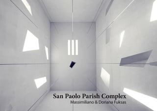
  • 1. Massimiliano & Doriana Fuksas San Paolo Parish Complex
  • 2.
  • 3. Introduction Structural Focus Systems Function Structural Systems: Walls Structural Systems: Roof Model-making Process Concept Model Analysis Structure Analysis Conclusion pg 4 ............................................................................................................... pg 6 ....................................................................................................... pg 7 ............................................................................................. pg 8 ........................................................................... pg 10 ......................................................................... pg 11 ....................................................................................... pg 14 ............................................................................. pg 17 ................................................................................................ pg 19 ........................................................................................ pg 20 .......................................................................................................
  • 5. “The suspension of a volume within another. Seeing through concrete heaven, from outside, to inside, to outside” -Massimiliano Fuksas “For the achievement of the architect was inspired by the vertical design of the church, in keeping with the liturgical celebration of the Mass and the intention was to redefine the concept of a link between heaven and earth through the momentum upward.” -Bellaumbria.net pg 5
  • 6. Site: Via del Roccolo 30, 06034 Foligno PG, Italy Project Year: 2001-2009 Client: Italian Episcopal Conference - Diocesi of Foligno Total area: 20,690 sqm Building area: 610 sqm Parish complex: 1,300 sqm symbol of rebirth - the San Paolo church designed by Massimiliano and Doriana Fuksas in 2009 was introduced after a devastating earthquake locally. It emerged as the winning entry for a competition - proposed for a developing town named Foligno, against a gorgeous mountainous backdrop in Italy. Til present, it functions to serve the San Paolo Parish’s Catholic congregation. The 25 metres tall, monolithic, box of a building stands out in strong contrast against the organic backdrop of huge mountains and amongst quaint residential buildings, yet, it manages to blend in with its seemingly modernist neighbours. Cladded in light grey, the concrete and steel church features distinctive “light canons” on its East and West facades. These structural openings ingeniously control and direct sunlight into the building. To the South, a gentle slope leads to a broad band of clear glass, with a cross marking the point of entry. The interior is a box within a box, position centrally and unified by a ceiling with three rectangular skylights which alludes to the holy trinity. The interior “box” is made of lightweight concrete on a steel frame, suspended from structural beams in the roof to hover above the floor at the height of 3 metres. As if personifying the paradox of faith, the San Paolo church is really a complex creation, in spite of staggering simplicity observed at first sight. Factual reference: http://www.theplan.it/J/index.php?option=com_content&view=article&id=88 2:complesso-parrocchiale-san-paolo&Itemid=367&lang=en A pg 6
  • 8. STRUCTURAL SYSTEM: WALLS Exterior Wall Materials: - The structure of the external wall consists of reinforced concrete columns with reinforced concrete beams forming the frames. - Styrofoam panels form the walls with reinforced concrete layer sandwiching the Styrofoam panels. - The concrete layers are linked to each other with metal elements. Holes for metal ties Styrofoam Panel Reinforced Concrete layer Column Beam Holes for metal ties Reinforced Concrete layer Styrofoam Panel Column Beam pg 8
  • 9. Interior Wall STRUCTURAL SYSTEM: WALLS Secondary roof beam Steel Structure Plaster Board Bracket on beam to connect to the steel structure Materials: - The internal walls are supported by steel structure which connects to the roof. - Plaster boards are installed to form the walls. Secondary roof beam Plaster Board Steel structure Bracket on beam to connect to the steel structure pg 9
  • 10. STRUCTURAL SYSTEM: ROOF Secondary roof beam Main roof beam Roof truss Materials: - The roof consists of 5 main beams and a series of secondary beams. The secondary beams support the “hung walls”. - The internal elements of the roof are formed by trusses. The roof is finished with a reinforced concrete slab Main roof beam Roof truss Secondary roof beam pg 10
  • 11. SYSTEMS FUNCTION Roof External wall Internal wall Light shafts - Barrier to harsh weather - Windbreaker - Provides thermal insulation - Waterproofs building interior - Control excessive lighting - Hold up roof beams - Isolate space for privacy - Provides added insulation - Control and direct sunlight into the main space - Creates an “upward momentum” - Define spatial hierarchy Barrier to harsh cold weather - Windbreaker - Provides thermal insulation - Waterproofs building interior (Direct rainwater away) - Control excessive lighting pg 10
  • 13. MODEL-MAKING PROCESS The I-beams and trusses pg 13
  • 16. MODEL-MAKING PROCESS The mock-up model The final model pg 16
  • 17. MODEL ANALYSIS Materials: Failure - Concrete (cement+sand+water) Initially, concrete was used for the construction of wall. However the it was predicted that the heavy load of concrete was not practical due to the large area of walls needed to be built. Other than that, there wereforeseen difficulties in controlling the thickness of the internal concrete walls. At the chosen scale, those walls would measure 0.2cm thick which might lead to severe concrete cracks. Success – Chipboard Instead of using concrete, chipboard was used to represent the concrete material as it is lighter in weight and could acheive the appropriate thickness needed without compromising in structural stability. Concrete Concrete Chipboard pg 17
  • 18. MODEL ANALYSIS Construction of light shafts: Slanted light shafts penetrating through the outer and inner walls are angled, therefore, their openings vary in position on both walls. This resulted in a tricky situation as the angles are varied and unknown to the team. Nevertheless, an ingenious solution was found by one of the teammates thereafter. The location of openings on both walls were figured out by calculating ratios with the formula below: d1/d2 = D1/D2 pg 18
  • 20. CONCLUSION The project has been a success despite several bumps faced along the way. Much knowledge with regards to solid building construction has been gained by the team. Many thanks to Ms Sufina who was supportive of the project and provided effective advice. pg 20
  • 21.
  • 22. PRODUCED BY: Choo Ai Lin [0317253]; Hiew Yen Nee [0314212]; Kian Soon Jean [0314978]; Leong Carmen [0314953]; Liew Hui En [0314920]; Tan Heng Yee [0314941]; Yong Seh Li [0314345] Building Construction 2 (ARC 2513) Project 2 - Solid Construction