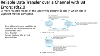
Building a Reliable Data Transfer
Protocol
Reliable Data Transfer over a Perfectly
Reliable Channel: rdt1.0
First consider the simplest case, in which the underlying channel is
completely reliable.
Reliable Data Transfer over a Channel with Bit
Errors: rdt2.0
A more realistic model of the underlying channel is one in which bits in
a packet may be corrupted.
Three additional protocol capabilities are
required in ARQ protocols to handle the
presence of bit errors:
Error detection
Receiver feedback: 0 for N 1 for P
Retransmission
The difficulty here is that if an ACK or NAK is corrupted, the sender has no way of knowing
whether or not the receiver has correctly received the last piece of transmitted data. Consider
three possibilities for handling corrupted ACKs or NAKs:
• For the first possibility, consider what a human might do in the message dictation scenario.
If the speaker didn’t understand the “OK” or “Please repeat that” reply from the receiver, the
speaker would probably ask, “What did you say?” (thus introducing a new type of sender-to-
receiver packet to our protocol).
• The receiver would then repeat the reply.
• But what if the speaker’s “What did you say?” is corrupted? The receiver, having no idea
whether the garbled sentence was part of the dictation or a request to repeat the last reply,
would probably then respond with “What did you say?” And then, of course, that response
might be garbled.
• A second alternative is to add enough checksum bits to allow the sender not only to detect,
but also to recover from, bit errors. This solves the immediate problem for a channel that can
corrupt packets but not lose them.
• A third approach is for the sender simply to resend the current data packet when it receives
a garbled ACK or NAK packet. This approach, however, introduces duplicate packets into the
sender-to-receiver channel. The fundamental difficulty with duplicate packets is that the
receiver doesn’t know whether the ACK or NAK it last sent was received correctly at the
sender. Thus, it cannot know apriori whether an arriving packet contains new data or is a
retransmission! (A 1 bit modulo 2–arithmetic sequence number will resolve the issue)
SENDER
RECEIVER
SENDER
RECEIVER
Reliable Data Transfer over a Lossy Channel with Bit Errors: rdt3.0
• Suppose now that in addition to corrupting bits, the underlying channel can lose packets as well,
a not-uncommon event in today’s computer networks (including the Internet). Two additional
concerns must now be addressed by the protocol: how to detect packet loss and what to do
when packet loss occurs.
• The techniques already developed in rdt2.2—will allow us to answer the latter (What to do)
concern.
• There are many possible approaches toward dealing with packet loss. In one approach put the
burden of detecting and recovering from lost packets on the sender. Suppose that the sender
transmits a data packet and either that packet, or the receiver’s ACK of that packet, gets lost. In
either case, no reply is forthcoming at the sender from the receiver. If the sender is willing to
wait long enough so that it is certain that a packet has been lost, it can simply retransmit the data
packet.
• The sender must clearly wait at least as long as a round-trip
delay between the sender and receiver (which may include
buffering at intermediate routers) plus whatever amount of
time is needed to process a packet at the receiver.
• Implementing a time-based retransmission mechanism
requires a countdown timer that can interrupt the sender
after a given amount of time has expired. The sender will
thus need to be able to (1) start the timer each time a packet
(either a first-time packet or a retransmission) is sent, (2)
respond to a timer interrupt (taking appropriate actions),
and (3) stop the timer.
Sender
RECEIVER
Because packet sequence numbers alternate
between 0 and 1, protocol rdt3.0 is
sometimes known as the alternating-bit
Pipelined Reliable Data Transfer Protocols
• At the heart of rdt3.0’s performance problem is the fact that it is a stop-and-wait protocol.
• The speed-of-light round-trip propagation delay between these two end systems, RTT, is
approximately 30 milliseconds. Suppose that they are connected by a channel with a
transmission rate, R, of 1 Gbps (109
bits per second). With a packet size, L, of 1,000 bytes
(8,000 bits) per packet, including both header fields and data, the time needed to actually
transmit the packet into the 1 Gbps link is
• The solution to this particular performance problem is simple: Rather than operate in a stop-
and-wait manner, the sender is allowed to send multiple packets without waiting for
acknowledgments, the utilization of the sender is improved. Since the many in-transit sender-
to-receiver packets can be visualized as filling a pipeline, this technique is known as
pipelining.
Pipelining has the following consequences for reliable data transfer protocols:
• The range of sequence numbers must be increased, since each in-transit packet (not
counting
retransmissions) must have a unique sequence number and there may be multiple, in-
transit,
unacknowledged packets.
• The sender and receiver sides of the protocols may have to buffer more than one packet.
Minimally, the
sender will have to buffer packets that have been transmitted but not yet acknowledged.
Buffering of
correctly received packets may also be needed at the receiver.
• The range of sequence numbers needed and the buffering requirements will depend on the
manner in which
a data transfer protocol responds to lost, corrupted, and overly delayed packets. Two basic
approaches
toward pipelined error recovery can be identified: Go-Back-N and selective repeat.
Go-Back-N (GBN) protocol
• In a Go-Back-N (GBN) protocol, the sender is allowed to transmit multiple packets (when
available) without waiting for an acknowledgment, but is constrained to have no more than
some maximum allowable number, N, of unacknowledged packets in the pipeline.
• If we define base to be the sequence number of the oldest unacknowledged packet and
nextseqnum to be the smallest unused sequence number (that is, the sequence number of
the next packet to be sent), then four intervals in the range of sequence numbers can be
identified. Sequence numbers in the interval [0,base-1] correspond to packets that have
already been transmitted and acknowledged.
• The interval[base,nextseqnum-1] corresponds to packets that have been sent but not yet
acknowledged. Sequence numbers in the interval [nextseqnum,base+N-1] can be used for
packets that can be sent immediately, should data arrive from the upper layer. Finally,
sequence numbers greater than or equal to base+N cannot be used until an unacknowledged
packet currently in the pipeline (specifically, the packet with sequence number base) has been
acknowledged.
Sender
Receiver
• The GBN sender must respond to three types of events:
• Invocation from above. When rdt_send() is called from above, the sender first checks
to see if the window is full, that is, whether there are N outstanding,
unacknowledged packets. If the window is not full, a packet is created and sent, and
variables are appropriately updated. If the window is full, the sender simply returns
the data back to the upper layer, an implicit indication that the window is full. The
upper layer would presumably then have to try again later.
• Receipt of an ACK. In our GBN protocol, an acknowledgment for a packet with
sequence number n will be taken to be a cumulative acknowledgment, indicating
that all packets with a sequence number up to and including n have been correctly
received at the receiver.
• A timeout event. The protocol’s name, “Go-Back-N,” is derived from the sender’s
behavior in the presence of lost or overly delayed packets. As in the stop-and-wait
protocol, a timer will again be used to recover from lost data or acknowledgment
packets. If a timeout occurs, the sender resends all packets that have been
previously sent but that have not yet been acknowledged.
• The receiver’s actions in GBN are also simple. If a packet with sequence number n is received
correctly and is in order (that is, the data last delivered to the upper layer came from a packet
with sequence number n – 1), the receiver sends an ACK for packet n and delivers the data
portion of the packet to the upper layer. In all other cases, the receiver discards the packet
and resends an ACK for the most recently received in-order packet.
• However, if packet n is lost, both it and packet n + 1 will eventually be retransmitted as a result
of the GBN retransmission rule at the sender. Thus, the receiver can simply discard packet n +
1. The advantage of this approach is the simplicity of receiver buffering—the receiver need
not buffer any out-of-order packets. Thus, while the sender must maintain the upper and
lower bounds of its window and the position of nextseqnum within this window, the only
piece of information the receiver need maintain is the sequence number of the next in-order
packet. This value is held in the variable expectedseqnum.
Selective Repeat (SR)
The SR receiver will acknowledge a correctly received packet whether or not it is in order. Out-of-
order packets are buffered until any missing packets (that is, packets with lower sequence
numbers) are received, at which point a batch of packets can be delivered in order to the upper
layer.
Sender
Receiver
Summary
Connection – Oriented : TCP
TCP is defined in RFC 793, RFC 1122, RFC 1323, RFC 2018, and RFC 2581
TCP is said to be connection-oriented because before one application
process can begin to send data to another, the two processes must first
“handshake” with each other—that is, they must send some
preliminary segments to each other to establish the parameters of the
ensuing data transfer.
Because the TCP protocol runs only in the end systems and not in the
intermediate network elements (routers and link-layer switches), the
intermediate network elements do not maintain TCP connection state.
• The client application process first informs the client transport layer that it wants to establish
a connection to a process in the server.
• The client first sends a special TCP segment; the server responds with a second special TCP
segment; and finally the client responds again with a third special segment.
• The first two segments carry no payload, that is, no application-layer data; the third of these
segments may carry a payload.
• Because three segments are sent between the two hosts, this connection-establishment
procedure is often referred to as a three-way handshake.
• Once a TCP connection is established, the two application processes can send data to each
other.
• The maximum amount of data that can be grabbed and placed in a segment is limited by the
maximum segment size (MSS).
• The MSS is typically set by first determining the length of the largest link-layer frame that can
be sent by the local sending host (the so-called maximum transmission unit, MTU) , and
then setting the MSS to ensure that a TCP segment (when encapsulated in an IP datagram)
plus the TCP/IP header length (typically 40 bytes) will fit into a single link-layer frame.
• Both Ethernet and PPP link-layer protocols have an MSS of 1,500 bytes.
• TCP pairs each chunk of client data with a TCP header, thereby forming TCP
segments.
• The segments are passed down to the network layer, where they are
separately encapsulated within network-layer IP datagrams. The IP datagrams
are then sent into the network.
• A TCP connection consists of buffers, variables, and a socket connection to a
process in one host, and another set of buffers, variables, and a socket
connection to a process in another host.
Sequence Numbers and Acknowledgment
Numbers
• The sequence number for a segment is the byte-stream number of
the first byte in the segment.
• The acknowledgment number that Host A puts in its segment is the
sequence number of the next byte Host A is expecting from Host B.
• A TCP connection randomly choose an initial sequence number.
Round-Trip Time Estimation and Timeout
• TCP, like our rdt protocol uses a timeout/retransmit mechanism to recover
from lost segments. The timeout should be larger than the connection’s
round-trip time (RTT), that is, the time from when a segment is sent until it is
acknowledged. Otherwise, unnecessary retransmissions would be sent.
Estimating the Round-Trip Time
Note that Estimated RTT is a weighted average of the Sample RTT values. This weighted average puts more weight on
recent samples than on old samples as the more recent samples better reflect the current congestion in the network.
In statistics, such an average is called an exponential weighted moving average (EWMA).
• In addition to having an estimate of the RTT, it is also valuable to have
a measure of the variability of the RTT. [RFC 6298] defines the RTT
variation, DevRTT, as an estimate of how much SampleRTT typically
deviates from EstimatedRTT:
• Note that DevRTT is an EWMA of the difference between SampleRTT
and EstimatedRTT. If the SampleRTT values have little fluctuation,
then DevRTT will be small; on the other hand, if there is a lot of
fluctuation, DevRTT will be large. The recommended value of β is
0.25.
Setting and Managing the Retransmission Timeout Interval
The interval should be greater than or equal to Estimated RTT, or
unnecessary retransmissions would be sent.
But the timeout interval should not be too much larger than Estimated
RTT; otherwise, when a segment is lost, TCP would not quickly retransmit
the segment, leading to large data transfer delays.
It is therefore desirable to set the timeout equal to the Estimated RTT plus
some margin. The margin should be large when there is a lot of fluctuation
in the SampleRTT values; it should be small when there is little fluctuation.
The value of DevRTT should thus come into play here. All of these
considerations are taken into account in TCP’s method for determining the
retransmission timeout interval:
Reliable Data Transfer Recall
TCP creates a reliable data transfer service on top of IP’s unreliable best effort
service.
TCP’s reliable data transfer service ensures that the data stream that a
process reads out of its TCP receive buffer is uncorrupted, without gaps,
without duplication, and in sequence; that is, the byte stream is exactly the
same byte stream that was sent by the end system on the other side of the
connection.
• Upon the occurrence of the first major event, TCP receives data from the application, encapsulates
the data in a segment, and passes the segment to IP. Note that each segment includes a sequence
number that is the byte-stream number of the first data byte in the segment.
TCP starts the timer when the segment is passed to IP. (It is helpful to think of the timer
as being associated with the oldest unacknowledged segment.) The expiration interval for this timer
is the TimeoutInterval , which is calculated from EstimatedRTT and DevRTT.
• The second major event is the timeout. TCP responds to the timeout event by retransmitting the
segment that caused the timeout. TCP then restarts the timer.
• The third major event that must be handled by the TCP sender is the arrival of an acknowledgment
segment (ACK) from the receiver (more specifically, a segment containing a valid ACK field value). On
the occurrence of this event, TCP compares the ACK value y with its variable SendBase . The TCP
state variable SendBase is the sequence number of the oldest unacknowledged byte. (Thus
SendBase–1 is the sequence number of the last byte that is known to have been received correctly
and in order at the receiver.)
As indicated earlier, TCP uses cumulative acknowledgments, so that y acknowledges the receipt
of all bytes before byte number y . If y > SendBase , then the ACK is acknowledging one or
more previously unacknowledged segments. Thus the sender updates its SendBase variable; it
also restarts the timer if there currently are any not-yet-acknowledged segments.
A Few Interesting Scenarios
the first scenario, in which Host A sends one segment
to Host B. Suppose that this segment has sequence
number 92 and contains 8 bytes of data.
After sending this segment, Host A waits
acknowledgment number 100.
Acknowledgment from B to A gets lost. In this case,
the timeout event occurs, and Host A retransmits the
same segment.
B receives the retransmission, it observes from the
sequence number that the segment contains data
that ha
As long as the ACK
for the second
segment arrives
before the new
timeout, the second
segment will not be
retransmitted.
Host A knows that
Host B has received
everything up
through byte 119;
Host A does not
resend either of the
two segments.
Doubling the Timeout Interval
The first concerns the length of the timeout interval after a timer expiration. In this modification,
whenever the timeout event occurs, TCP retransmits the not-yet acknowledged segment with
the smallest sequence number. But each time TCP retransmits, it sets the next timeout interval to
twice the previous value, rather than deriving it from the last EstimatedRTT and DevRTT.
For example, suppose TimeoutInterval associated with the oldest not yet acknowledged segment
is .75 sec when the timer first expires. TCP will then retransmit this segment and set the new
expiration time to 1.5 sec. If the timer expires again 1.5 sec later, TCP will again retransmit this
segment, now setting the expiration time to 3.0 sec.
However, whenever the timer is started after either of the two other events (that is, data
received from application above, and ACK received), the TimeoutInterval is derived from the
most recent values of EstimatedRTT and DevRTT. This modification provides a limited form of
congestion control.
Fast Retransmit
• One of the problems with timeout-triggered retransmissions is that the timeout period can be relatively
long. When a segment is lost, this long timeout period forces the sender to delay resending the lost
packet, thereby increasing the end-to-end delay.
• The sender can often detect packet loss well before the timeout event occurs by noting so-called
duplicate ACKs. A duplicate ACK is an ACK that reacknowledges a segment for which the sender has
already received an earlier acknowledgment.
• To understand the sender’s response to a duplicate ACK, we must look at why the receiver sends a
duplicate ACK in the first place. Table summarizes the TCP receiver’s ACK generation policy [RFC 5681].
• When a TCP receiver receives a segment with a sequence number that is larger than the next, expected,
in-order sequence number, it detects a gap in the data stream—that is, a missing segment. This gap
could be the result of lost or reordered segments within the network.
• Since TCP does not use negative acknowledgments, the receiver cannot send an explicit negative
acknowledgment back to the sender. Instead, it simply reacknowledges (that is, generates a duplicate
ACK for) the last in-order byte of data it has received.
• Because a sender often sends a large number of segments back to back, if one segment is lost, there
will likely be many back-to-back duplicate ACKs. If the TCP sender receives three duplicate ACKs for the
same data, it takes this as an indication that the segment following the segment that has been ACKed
three times has been lost. (In the homework problems, we consider the question of why the sender
waits for three duplicate ACKs, rather than just a single duplicate ACK
• In the case that three duplicate ACKs are received, the TCP sender
performs a fast retransmit [RFC 5681], retransmitting the missing
segment before that segment’s timer expires.
Go-Back-N or Selective Repeat?
• Is TCP a GBN or an SR protocol? Recall that TCP acknowledgments are cumulative and
correctly received but out-of-order segments are not individually ACKed by the receiver. TCP
would not even retransmit segment n if the acknowledgment for segment n+1 arrived before
the timeout for segment n.
• A proposed modification to TCP, the so-called selective acknowledgment [RFC 2018], allows
a TCP receiver to acknowledge out-of-order segments selectively rather than just cumulatively
acknowledging the last correctly received, in-order segment.
• When combined with selective retransmission—skipping the retransmission of segments that
have already been selectively acknowledged by the receiver—TCP looks a lot like our generic
SR protocol. Thus, TCP’s error-recovery mechanism is probably best categorized as a hybrid of
GBN and SR protocols.
Flow Control
• Recall that the hosts on each side of a TCP connection set aside a receive buffer for the connection.
When the TCP connection receives bytes that are correct and in sequence, it places the data in the
receive buffer. If the application is relatively slow at reading the data, the sender can very easily
overflow the connection’s receive buffer by sending too much data too quickly.
• TCP provides a flow-control service to its applications to eliminate the possibility of the sender
overflowing the receiver’s buffer. Flow control is thus a speed-matching service—matching the rate at
which the sender is sending against the rate at which the receiving application is reading. As noted
earlier, a TCP sender can also be throttled due to congestion within the IP network; this form of sender
control is referred to as congestion control.
• TCP provides flow control by having the sender maintain a variable called the receive window.
Informally, the receive window is used to give the sender an idea of how much free buffer space
isavailable at the receiver. Because TCP is full-duplex, the sender at each side of the connection
maintains a distinct receive window. Let’s investigate the receive window in the context of a file
transfer.
• Suppose that Host A is sending a large file to Host B over a TCP connection. Host B allocates a receive
buffer to this connection; denote its size by RcvBuffer . From time to time, the application process in
Host B reads from the buffer. Define the following variables:
• LastByteRead : the number of the last byte in the data stream read from the buffer by the application
process in B
• LastByteRcvd : the number of the last byte in the data stream that has arrived from the network and has
been placed in the receive buffer at B
Host B tells Host A how much spare
room it has in the connection buffer
by placing its current value of rwnd
in the receive window field of every
segment it sends to A.
Initially, Host B sets rwnd = RcvBuffer
.
• Host A in turn keeps track of two variables, LastByteSent and LastByteAcked , which have
obvious meanings. Note that the difference between these two variables, LastByteSent –
LastByteAcked , is the amount of unacknowledged data that A has sent into the connection.
• By keeping the amount of unacknowledged data less than the value of rwnd , Host A is
assured of not overflowing B.
• There is one minor technical problem with this scheme. To see this, suppose Host B’s
receive buffer becomes full so that rwnd = 0. After advertising rwnd = 0 to Host A, also
suppose that B has nothing to send to A.
• Now consider what happens. As the application process at B empties the buffer, TCP does
not send new segments with new rwnd values to Host A; indeed, TCP sends a segment to
Host A only if it has data to send or if it has an acknowledgment to send. Therefore, Host A
is never informed that some space has opened up in Host B’s receive buffer—Host A is
blocked and can transmit no more data!
• To solve this problem, the TCP specification requires Host A to continue to send segments
with one data byte when B’s receive window is zero. These segments will be acknowledged
by the receiver. Eventually the buffer will begin to empty and the acknowledgments will
contain a nonzero rwnd value.
TCP Connection Management
• TCP client establishing a TCP connection with the TCP in the server in the following manner:
• Step 1. The client-side TCP first sends a special TCP segment to the server-side TCP. SYN bit, is set to 1. For
this reason, this special segment is referred to as a SYN segment. In addition, the client randomly chooses
an initial sequence number ( client_isn ) and puts this number in the sequence number field of the initial
TCP SYN segment. This segment is encapsulated within an IP datagram and sent to the server. There has
been considerable interest in properly randomizing the choice of the client_isn in order to avoid certain
security attacks[CERT 2001–09].
• Step 2. Once the IP datagram containing the TCP SYN segment arrives at the server host, the server
extracts the TCP SYN segment from the datagram, allocates the TCP buffers and variables to the
connection, and sends a connection-granted segment to the client TCP. This connection-granted segment
contain three important pieces of information in the segment header. First, the SYN bit is set to 1. Second,
the acknowledgment field of the TCP segment header is set to client_isn+1 . Finally, the server chooses its
own initial sequence number ( server_isn ) and puts this value in the sequence number field of the TCP
segment header. The connection-granted segment is referred to as a SYNACK segment
• Step 3. Upon receiving the SYNACK segment, the client also allocates buffers and variables to the
connection. The client host then sends the server yet another segment; this last segment acknowledges
the server’s connection-granted segment (the client does so by putting the value server_isn+1 in the
acknowledgment field of the TCP segment header). The SYN bit is set to zero, since the connection is
established. This third stage of the three-way handshake may carry client-to-server data in the segment
payload.
• The client application process issues a close
command. This causes the client TCP to send
a special TCP segment to the server process.
This special segment has a flag bit in the
segment’s header, the FIN bit set to 1.
• When the server receives this segment, it
sends the client an acknowledgment
segment in return. The server then sends its
own shutdown segment, which has the FIN
bit set to 1.
• Finally, the client acknowledges the server’s
shutdown segment. At this point, all the
resources in the two hosts are now
deallocated.
• During the life of a TCP connection, the TCP protocol running in each host makes transition
through various TCP states
• Consider what happens when a host receives a TCP segment whose port numbers or source
IP address do not match with any of the ongoing sockets in the host. For example, suppose a
host receives a TCP SYN packet with destination port 80, but the host is not accepting
connections on port 80 (that is, it is not running a Web server on port 80).
• Then the host will send a special reset segment to the source. This TCP segment has the RST
flag bit set to 1. Thus, when a host sends a reset segment, it is telling the source “I don’t have
a socket for that segment. Please do not resend the segment.”
Principles of Congestion Control
• network congestion—too many sources attempting to send data at too high a rate. To treat
the cause of network congestion, mechanisms are needed to throttle senders in the face of
network congestion.
The Causes and the Costs of Congestion
Scenario 1: Two Senders, a Router with Infinite Buffers
For a sending rate between 0 and R/2, the throughput at the receiver equals the sender’s sending rate—
everything sent by the sender is received at the receiver with a finite delay. When the sending rate is above
R/2, however, the throughput is only R/2. This upper limit on throughput is a consequence of the sharing of
link capacity between two connections. The link simply cannot deliver packets to a receiver at a steady-state
rate that exceeds R/2. No matter how high Hosts A and B set their sending rates, they will each never see a
throughput higher than R/2.
As the sending rate approaches R/2 (from the left), the average delay becomes larger and larger.
When the sending rate exceeds R/2, the average number of queued packets in the router is
unbounded, and the average delay between source and destination becomes infinite (assuming that
the connections operate at these sending rates for an infinite period of time and there is an infinite
amount of buffering available). Thus, while operating at an aggregate throughput of near R may be
ideal from a throughput standpoint, it is far from ideal from a delay standpoint.
Even in this (extremely) idealized scenario, we’ve already found one cost of a congested network—large
queuing delays are experienced as the packet-arrival rate nears the link capacity.
Scenario 2: Two Senders and a Router with Finite Buffers
• First, the amount of router buffering is assumed to be finite. A consequence of this real-world assumption
is that packets will be dropped when arriving to an already-full buffer. Second, we assume that each
connection is reliable.
• If a packet containing a transport-level segment is dropped at the router, the sender will eventually
retransmit it. Because packets can be retransmitted, we must now be more careful with our use of the
term sending rate.
• Specifically, let us again denote the rate at which the application sends original data into the socket by λ
bytes/sec. The rate at which the transport layer sends segments (containing original data and
retransmitted data) into the network will be denoted λ′ bytes/sec. λ′ is sometimes referred to as the
offered load to the network.
• The performance realized under scenario 2 will now depend strongly on how retransmission
is performed. First, consider the unrealistic case that Host A is able to somehow (magically!)
determine whether or not a buffer is free in the router and thus sends a packet only when a
buffer is free. In this case, no loss would occur, λ would be equal to λ′in, and the throughput
of the connection would be equal to λ .
• From a throughput standpoint, performance is ideal— everything that is sent is received.
Note that the average host sending rate cannot exceed R/2 under this scenario, since packet
loss is assumed never to occur (fig. a).
Scenario 3: Four Senders, Routers with Finite Buffers, and Multihop Paths
• In our final congestion scenario, four hosts transmit packets, each over overlapping two-hop
paths again assume that each host uses a timeout/retransmission mechanism to implement a
reliable data transfer service, that all hosts have the same value of λin , and that all router links
have capacity R bytes/sec.
Approaches to Congestion Control
• End-to-end congestion control. In an end-to-end approach to congestion control, the
network layer provides no explicit support to the transport layer for congestion-control
purposes. Even the presence of network congestion must be inferred by the end systems
based only on observed network behavior (for example, packet loss and delay). TCP segment
loss (as indicated by a timeout or the receipt of three duplicate acknowledgments) is taken as
an indication of network congestion, and TCP decreases its window size accordingly.
• Network-assisted congestion control. With network-assisted congestion control, routers
provide explicit feedback to the sender and/or receiver regarding the congestion state of the
network. This feedback may be as simple as a single bit indicating congestion at a link. More
sophisticated feedback is also possible- a router informs the sender of the maximum host
sending rate it (the router) can support on an outgoing link.
• For network-assisted congestion control, congestion information is typically fed back from the network to
the sender in one of two ways. First,direct feedback may be sent from a network router to the sender.
• The second and more common form of notification occurs when a router marks/updates a field in a
packet flowing from sender to receiver to indicate congestion. Upon receipt of a marked packet, the
receiver then notifies the sender of the congestion indication. This latter form of notification takes a full
round-trip time.

Building a Reliable Data Transfer Protocol.pptx

  • 1.
    Building a ReliableData Transfer Protocol
  • 2.
    Reliable Data Transferover a Perfectly Reliable Channel: rdt1.0 First consider the simplest case, in which the underlying channel is completely reliable.
  • 3.
    Reliable Data Transferover a Channel with Bit Errors: rdt2.0 A more realistic model of the underlying channel is one in which bits in a packet may be corrupted. Three additional protocol capabilities are required in ARQ protocols to handle the presence of bit errors: Error detection Receiver feedback: 0 for N 1 for P Retransmission
  • 4.
    The difficulty hereis that if an ACK or NAK is corrupted, the sender has no way of knowing whether or not the receiver has correctly received the last piece of transmitted data. Consider three possibilities for handling corrupted ACKs or NAKs: • For the first possibility, consider what a human might do in the message dictation scenario. If the speaker didn’t understand the “OK” or “Please repeat that” reply from the receiver, the speaker would probably ask, “What did you say?” (thus introducing a new type of sender-to- receiver packet to our protocol). • The receiver would then repeat the reply. • But what if the speaker’s “What did you say?” is corrupted? The receiver, having no idea whether the garbled sentence was part of the dictation or a request to repeat the last reply, would probably then respond with “What did you say?” And then, of course, that response might be garbled. • A second alternative is to add enough checksum bits to allow the sender not only to detect, but also to recover from, bit errors. This solves the immediate problem for a channel that can corrupt packets but not lose them. • A third approach is for the sender simply to resend the current data packet when it receives a garbled ACK or NAK packet. This approach, however, introduces duplicate packets into the sender-to-receiver channel. The fundamental difficulty with duplicate packets is that the receiver doesn’t know whether the ACK or NAK it last sent was received correctly at the sender. Thus, it cannot know apriori whether an arriving packet contains new data or is a retransmission! (A 1 bit modulo 2–arithmetic sequence number will resolve the issue)
  • 5.
  • 6.
  • 7.
  • 8.
  • 9.
    Reliable Data Transferover a Lossy Channel with Bit Errors: rdt3.0 • Suppose now that in addition to corrupting bits, the underlying channel can lose packets as well, a not-uncommon event in today’s computer networks (including the Internet). Two additional concerns must now be addressed by the protocol: how to detect packet loss and what to do when packet loss occurs. • The techniques already developed in rdt2.2—will allow us to answer the latter (What to do) concern. • There are many possible approaches toward dealing with packet loss. In one approach put the burden of detecting and recovering from lost packets on the sender. Suppose that the sender transmits a data packet and either that packet, or the receiver’s ACK of that packet, gets lost. In either case, no reply is forthcoming at the sender from the receiver. If the sender is willing to wait long enough so that it is certain that a packet has been lost, it can simply retransmit the data packet.
  • 10.
    • The sendermust clearly wait at least as long as a round-trip delay between the sender and receiver (which may include buffering at intermediate routers) plus whatever amount of time is needed to process a packet at the receiver. • Implementing a time-based retransmission mechanism requires a countdown timer that can interrupt the sender after a given amount of time has expired. The sender will thus need to be able to (1) start the timer each time a packet (either a first-time packet or a retransmission) is sent, (2) respond to a timer interrupt (taking appropriate actions), and (3) stop the timer.
  • 11.
  • 12.
    RECEIVER Because packet sequencenumbers alternate between 0 and 1, protocol rdt3.0 is sometimes known as the alternating-bit
  • 14.
    Pipelined Reliable DataTransfer Protocols • At the heart of rdt3.0’s performance problem is the fact that it is a stop-and-wait protocol. • The speed-of-light round-trip propagation delay between these two end systems, RTT, is approximately 30 milliseconds. Suppose that they are connected by a channel with a transmission rate, R, of 1 Gbps (109 bits per second). With a packet size, L, of 1,000 bytes (8,000 bits) per packet, including both header fields and data, the time needed to actually transmit the packet into the 1 Gbps link is
  • 16.
    • The solutionto this particular performance problem is simple: Rather than operate in a stop- and-wait manner, the sender is allowed to send multiple packets without waiting for acknowledgments, the utilization of the sender is improved. Since the many in-transit sender- to-receiver packets can be visualized as filling a pipeline, this technique is known as pipelining. Pipelining has the following consequences for reliable data transfer protocols: • The range of sequence numbers must be increased, since each in-transit packet (not counting retransmissions) must have a unique sequence number and there may be multiple, in- transit, unacknowledged packets. • The sender and receiver sides of the protocols may have to buffer more than one packet. Minimally, the sender will have to buffer packets that have been transmitted but not yet acknowledged. Buffering of correctly received packets may also be needed at the receiver. • The range of sequence numbers needed and the buffering requirements will depend on the manner in which a data transfer protocol responds to lost, corrupted, and overly delayed packets. Two basic approaches toward pipelined error recovery can be identified: Go-Back-N and selective repeat.
  • 18.
    Go-Back-N (GBN) protocol •In a Go-Back-N (GBN) protocol, the sender is allowed to transmit multiple packets (when available) without waiting for an acknowledgment, but is constrained to have no more than some maximum allowable number, N, of unacknowledged packets in the pipeline. • If we define base to be the sequence number of the oldest unacknowledged packet and nextseqnum to be the smallest unused sequence number (that is, the sequence number of the next packet to be sent), then four intervals in the range of sequence numbers can be identified. Sequence numbers in the interval [0,base-1] correspond to packets that have already been transmitted and acknowledged. • The interval[base,nextseqnum-1] corresponds to packets that have been sent but not yet acknowledged. Sequence numbers in the interval [nextseqnum,base+N-1] can be used for packets that can be sent immediately, should data arrive from the upper layer. Finally, sequence numbers greater than or equal to base+N cannot be used until an unacknowledged packet currently in the pipeline (specifically, the packet with sequence number base) has been acknowledged.
  • 19.
  • 20.
  • 21.
    • The GBNsender must respond to three types of events: • Invocation from above. When rdt_send() is called from above, the sender first checks to see if the window is full, that is, whether there are N outstanding, unacknowledged packets. If the window is not full, a packet is created and sent, and variables are appropriately updated. If the window is full, the sender simply returns the data back to the upper layer, an implicit indication that the window is full. The upper layer would presumably then have to try again later. • Receipt of an ACK. In our GBN protocol, an acknowledgment for a packet with sequence number n will be taken to be a cumulative acknowledgment, indicating that all packets with a sequence number up to and including n have been correctly received at the receiver. • A timeout event. The protocol’s name, “Go-Back-N,” is derived from the sender’s behavior in the presence of lost or overly delayed packets. As in the stop-and-wait protocol, a timer will again be used to recover from lost data or acknowledgment packets. If a timeout occurs, the sender resends all packets that have been previously sent but that have not yet been acknowledged.
  • 22.
    • The receiver’sactions in GBN are also simple. If a packet with sequence number n is received correctly and is in order (that is, the data last delivered to the upper layer came from a packet with sequence number n – 1), the receiver sends an ACK for packet n and delivers the data portion of the packet to the upper layer. In all other cases, the receiver discards the packet and resends an ACK for the most recently received in-order packet. • However, if packet n is lost, both it and packet n + 1 will eventually be retransmitted as a result of the GBN retransmission rule at the sender. Thus, the receiver can simply discard packet n + 1. The advantage of this approach is the simplicity of receiver buffering—the receiver need not buffer any out-of-order packets. Thus, while the sender must maintain the upper and lower bounds of its window and the position of nextseqnum within this window, the only piece of information the receiver need maintain is the sequence number of the next in-order packet. This value is held in the variable expectedseqnum.
  • 24.
    Selective Repeat (SR) TheSR receiver will acknowledge a correctly received packet whether or not it is in order. Out-of- order packets are buffered until any missing packets (that is, packets with lower sequence numbers) are received, at which point a batch of packets can be delivered in order to the upper layer.
  • 25.
  • 26.
  • 29.
  • 30.
    Connection – Oriented: TCP TCP is defined in RFC 793, RFC 1122, RFC 1323, RFC 2018, and RFC 2581 TCP is said to be connection-oriented because before one application process can begin to send data to another, the two processes must first “handshake” with each other—that is, they must send some preliminary segments to each other to establish the parameters of the ensuing data transfer. Because the TCP protocol runs only in the end systems and not in the intermediate network elements (routers and link-layer switches), the intermediate network elements do not maintain TCP connection state.
  • 31.
    • The clientapplication process first informs the client transport layer that it wants to establish a connection to a process in the server. • The client first sends a special TCP segment; the server responds with a second special TCP segment; and finally the client responds again with a third special segment. • The first two segments carry no payload, that is, no application-layer data; the third of these segments may carry a payload. • Because three segments are sent between the two hosts, this connection-establishment procedure is often referred to as a three-way handshake. • Once a TCP connection is established, the two application processes can send data to each other. • The maximum amount of data that can be grabbed and placed in a segment is limited by the maximum segment size (MSS). • The MSS is typically set by first determining the length of the largest link-layer frame that can be sent by the local sending host (the so-called maximum transmission unit, MTU) , and then setting the MSS to ensure that a TCP segment (when encapsulated in an IP datagram) plus the TCP/IP header length (typically 40 bytes) will fit into a single link-layer frame. • Both Ethernet and PPP link-layer protocols have an MSS of 1,500 bytes.
  • 32.
    • TCP pairseach chunk of client data with a TCP header, thereby forming TCP segments. • The segments are passed down to the network layer, where they are separately encapsulated within network-layer IP datagrams. The IP datagrams are then sent into the network. • A TCP connection consists of buffers, variables, and a socket connection to a process in one host, and another set of buffers, variables, and a socket connection to a process in another host.
  • 33.
    Sequence Numbers andAcknowledgment Numbers • The sequence number for a segment is the byte-stream number of the first byte in the segment. • The acknowledgment number that Host A puts in its segment is the sequence number of the next byte Host A is expecting from Host B. • A TCP connection randomly choose an initial sequence number.
  • 34.
    Round-Trip Time Estimationand Timeout • TCP, like our rdt protocol uses a timeout/retransmit mechanism to recover from lost segments. The timeout should be larger than the connection’s round-trip time (RTT), that is, the time from when a segment is sent until it is acknowledged. Otherwise, unnecessary retransmissions would be sent. Estimating the Round-Trip Time
  • 35.
    Note that EstimatedRTT is a weighted average of the Sample RTT values. This weighted average puts more weight on recent samples than on old samples as the more recent samples better reflect the current congestion in the network. In statistics, such an average is called an exponential weighted moving average (EWMA).
  • 36.
    • In additionto having an estimate of the RTT, it is also valuable to have a measure of the variability of the RTT. [RFC 6298] defines the RTT variation, DevRTT, as an estimate of how much SampleRTT typically deviates from EstimatedRTT: • Note that DevRTT is an EWMA of the difference between SampleRTT and EstimatedRTT. If the SampleRTT values have little fluctuation, then DevRTT will be small; on the other hand, if there is a lot of fluctuation, DevRTT will be large. The recommended value of β is 0.25.
  • 37.
    Setting and Managingthe Retransmission Timeout Interval The interval should be greater than or equal to Estimated RTT, or unnecessary retransmissions would be sent. But the timeout interval should not be too much larger than Estimated RTT; otherwise, when a segment is lost, TCP would not quickly retransmit the segment, leading to large data transfer delays. It is therefore desirable to set the timeout equal to the Estimated RTT plus some margin. The margin should be large when there is a lot of fluctuation in the SampleRTT values; it should be small when there is little fluctuation. The value of DevRTT should thus come into play here. All of these considerations are taken into account in TCP’s method for determining the retransmission timeout interval:
  • 38.
    Reliable Data TransferRecall TCP creates a reliable data transfer service on top of IP’s unreliable best effort service. TCP’s reliable data transfer service ensures that the data stream that a process reads out of its TCP receive buffer is uncorrupted, without gaps, without duplication, and in sequence; that is, the byte stream is exactly the same byte stream that was sent by the end system on the other side of the connection.
  • 40.
    • Upon theoccurrence of the first major event, TCP receives data from the application, encapsulates the data in a segment, and passes the segment to IP. Note that each segment includes a sequence number that is the byte-stream number of the first data byte in the segment. TCP starts the timer when the segment is passed to IP. (It is helpful to think of the timer as being associated with the oldest unacknowledged segment.) The expiration interval for this timer is the TimeoutInterval , which is calculated from EstimatedRTT and DevRTT. • The second major event is the timeout. TCP responds to the timeout event by retransmitting the segment that caused the timeout. TCP then restarts the timer. • The third major event that must be handled by the TCP sender is the arrival of an acknowledgment segment (ACK) from the receiver (more specifically, a segment containing a valid ACK field value). On the occurrence of this event, TCP compares the ACK value y with its variable SendBase . The TCP state variable SendBase is the sequence number of the oldest unacknowledged byte. (Thus SendBase–1 is the sequence number of the last byte that is known to have been received correctly and in order at the receiver.) As indicated earlier, TCP uses cumulative acknowledgments, so that y acknowledges the receipt of all bytes before byte number y . If y > SendBase , then the ACK is acknowledging one or more previously unacknowledged segments. Thus the sender updates its SendBase variable; it also restarts the timer if there currently are any not-yet-acknowledged segments.
  • 41.
    A Few InterestingScenarios the first scenario, in which Host A sends one segment to Host B. Suppose that this segment has sequence number 92 and contains 8 bytes of data. After sending this segment, Host A waits acknowledgment number 100. Acknowledgment from B to A gets lost. In this case, the timeout event occurs, and Host A retransmits the same segment. B receives the retransmission, it observes from the sequence number that the segment contains data that ha
  • 42.
    As long asthe ACK for the second segment arrives before the new timeout, the second segment will not be retransmitted. Host A knows that Host B has received everything up through byte 119; Host A does not resend either of the two segments.
  • 43.
    Doubling the TimeoutInterval The first concerns the length of the timeout interval after a timer expiration. In this modification, whenever the timeout event occurs, TCP retransmits the not-yet acknowledged segment with the smallest sequence number. But each time TCP retransmits, it sets the next timeout interval to twice the previous value, rather than deriving it from the last EstimatedRTT and DevRTT. For example, suppose TimeoutInterval associated with the oldest not yet acknowledged segment is .75 sec when the timer first expires. TCP will then retransmit this segment and set the new expiration time to 1.5 sec. If the timer expires again 1.5 sec later, TCP will again retransmit this segment, now setting the expiration time to 3.0 sec. However, whenever the timer is started after either of the two other events (that is, data received from application above, and ACK received), the TimeoutInterval is derived from the most recent values of EstimatedRTT and DevRTT. This modification provides a limited form of congestion control.
  • 44.
    Fast Retransmit • Oneof the problems with timeout-triggered retransmissions is that the timeout period can be relatively long. When a segment is lost, this long timeout period forces the sender to delay resending the lost packet, thereby increasing the end-to-end delay. • The sender can often detect packet loss well before the timeout event occurs by noting so-called duplicate ACKs. A duplicate ACK is an ACK that reacknowledges a segment for which the sender has already received an earlier acknowledgment. • To understand the sender’s response to a duplicate ACK, we must look at why the receiver sends a duplicate ACK in the first place. Table summarizes the TCP receiver’s ACK generation policy [RFC 5681]. • When a TCP receiver receives a segment with a sequence number that is larger than the next, expected, in-order sequence number, it detects a gap in the data stream—that is, a missing segment. This gap could be the result of lost or reordered segments within the network. • Since TCP does not use negative acknowledgments, the receiver cannot send an explicit negative acknowledgment back to the sender. Instead, it simply reacknowledges (that is, generates a duplicate ACK for) the last in-order byte of data it has received. • Because a sender often sends a large number of segments back to back, if one segment is lost, there will likely be many back-to-back duplicate ACKs. If the TCP sender receives three duplicate ACKs for the same data, it takes this as an indication that the segment following the segment that has been ACKed three times has been lost. (In the homework problems, we consider the question of why the sender waits for three duplicate ACKs, rather than just a single duplicate ACK
  • 45.
    • In thecase that three duplicate ACKs are received, the TCP sender performs a fast retransmit [RFC 5681], retransmitting the missing segment before that segment’s timer expires.
  • 46.
    Go-Back-N or SelectiveRepeat? • Is TCP a GBN or an SR protocol? Recall that TCP acknowledgments are cumulative and correctly received but out-of-order segments are not individually ACKed by the receiver. TCP would not even retransmit segment n if the acknowledgment for segment n+1 arrived before the timeout for segment n. • A proposed modification to TCP, the so-called selective acknowledgment [RFC 2018], allows a TCP receiver to acknowledge out-of-order segments selectively rather than just cumulatively acknowledging the last correctly received, in-order segment. • When combined with selective retransmission—skipping the retransmission of segments that have already been selectively acknowledged by the receiver—TCP looks a lot like our generic SR protocol. Thus, TCP’s error-recovery mechanism is probably best categorized as a hybrid of GBN and SR protocols.
  • 47.
    Flow Control • Recallthat the hosts on each side of a TCP connection set aside a receive buffer for the connection. When the TCP connection receives bytes that are correct and in sequence, it places the data in the receive buffer. If the application is relatively slow at reading the data, the sender can very easily overflow the connection’s receive buffer by sending too much data too quickly. • TCP provides a flow-control service to its applications to eliminate the possibility of the sender overflowing the receiver’s buffer. Flow control is thus a speed-matching service—matching the rate at which the sender is sending against the rate at which the receiving application is reading. As noted earlier, a TCP sender can also be throttled due to congestion within the IP network; this form of sender control is referred to as congestion control. • TCP provides flow control by having the sender maintain a variable called the receive window. Informally, the receive window is used to give the sender an idea of how much free buffer space isavailable at the receiver. Because TCP is full-duplex, the sender at each side of the connection maintains a distinct receive window. Let’s investigate the receive window in the context of a file transfer. • Suppose that Host A is sending a large file to Host B over a TCP connection. Host B allocates a receive buffer to this connection; denote its size by RcvBuffer . From time to time, the application process in Host B reads from the buffer. Define the following variables: • LastByteRead : the number of the last byte in the data stream read from the buffer by the application process in B • LastByteRcvd : the number of the last byte in the data stream that has arrived from the network and has been placed in the receive buffer at B
  • 48.
    Host B tellsHost A how much spare room it has in the connection buffer by placing its current value of rwnd in the receive window field of every segment it sends to A. Initially, Host B sets rwnd = RcvBuffer .
  • 49.
    • Host Ain turn keeps track of two variables, LastByteSent and LastByteAcked , which have obvious meanings. Note that the difference between these two variables, LastByteSent – LastByteAcked , is the amount of unacknowledged data that A has sent into the connection. • By keeping the amount of unacknowledged data less than the value of rwnd , Host A is assured of not overflowing B. • There is one minor technical problem with this scheme. To see this, suppose Host B’s receive buffer becomes full so that rwnd = 0. After advertising rwnd = 0 to Host A, also suppose that B has nothing to send to A. • Now consider what happens. As the application process at B empties the buffer, TCP does not send new segments with new rwnd values to Host A; indeed, TCP sends a segment to Host A only if it has data to send or if it has an acknowledgment to send. Therefore, Host A is never informed that some space has opened up in Host B’s receive buffer—Host A is blocked and can transmit no more data! • To solve this problem, the TCP specification requires Host A to continue to send segments with one data byte when B’s receive window is zero. These segments will be acknowledged by the receiver. Eventually the buffer will begin to empty and the acknowledgments will contain a nonzero rwnd value.
  • 50.
    TCP Connection Management •TCP client establishing a TCP connection with the TCP in the server in the following manner: • Step 1. The client-side TCP first sends a special TCP segment to the server-side TCP. SYN bit, is set to 1. For this reason, this special segment is referred to as a SYN segment. In addition, the client randomly chooses an initial sequence number ( client_isn ) and puts this number in the sequence number field of the initial TCP SYN segment. This segment is encapsulated within an IP datagram and sent to the server. There has been considerable interest in properly randomizing the choice of the client_isn in order to avoid certain security attacks[CERT 2001–09]. • Step 2. Once the IP datagram containing the TCP SYN segment arrives at the server host, the server extracts the TCP SYN segment from the datagram, allocates the TCP buffers and variables to the connection, and sends a connection-granted segment to the client TCP. This connection-granted segment contain three important pieces of information in the segment header. First, the SYN bit is set to 1. Second, the acknowledgment field of the TCP segment header is set to client_isn+1 . Finally, the server chooses its own initial sequence number ( server_isn ) and puts this value in the sequence number field of the TCP segment header. The connection-granted segment is referred to as a SYNACK segment • Step 3. Upon receiving the SYNACK segment, the client also allocates buffers and variables to the connection. The client host then sends the server yet another segment; this last segment acknowledges the server’s connection-granted segment (the client does so by putting the value server_isn+1 in the acknowledgment field of the TCP segment header). The SYN bit is set to zero, since the connection is established. This third stage of the three-way handshake may carry client-to-server data in the segment payload.
  • 52.
    • The clientapplication process issues a close command. This causes the client TCP to send a special TCP segment to the server process. This special segment has a flag bit in the segment’s header, the FIN bit set to 1. • When the server receives this segment, it sends the client an acknowledgment segment in return. The server then sends its own shutdown segment, which has the FIN bit set to 1. • Finally, the client acknowledges the server’s shutdown segment. At this point, all the resources in the two hosts are now deallocated.
  • 53.
    • During thelife of a TCP connection, the TCP protocol running in each host makes transition through various TCP states
  • 55.
    • Consider whathappens when a host receives a TCP segment whose port numbers or source IP address do not match with any of the ongoing sockets in the host. For example, suppose a host receives a TCP SYN packet with destination port 80, but the host is not accepting connections on port 80 (that is, it is not running a Web server on port 80). • Then the host will send a special reset segment to the source. This TCP segment has the RST flag bit set to 1. Thus, when a host sends a reset segment, it is telling the source “I don’t have a socket for that segment. Please do not resend the segment.”
  • 56.
    Principles of CongestionControl • network congestion—too many sources attempting to send data at too high a rate. To treat the cause of network congestion, mechanisms are needed to throttle senders in the face of network congestion. The Causes and the Costs of Congestion Scenario 1: Two Senders, a Router with Infinite Buffers
  • 57.
    For a sendingrate between 0 and R/2, the throughput at the receiver equals the sender’s sending rate— everything sent by the sender is received at the receiver with a finite delay. When the sending rate is above R/2, however, the throughput is only R/2. This upper limit on throughput is a consequence of the sharing of link capacity between two connections. The link simply cannot deliver packets to a receiver at a steady-state rate that exceeds R/2. No matter how high Hosts A and B set their sending rates, they will each never see a throughput higher than R/2. As the sending rate approaches R/2 (from the left), the average delay becomes larger and larger. When the sending rate exceeds R/2, the average number of queued packets in the router is unbounded, and the average delay between source and destination becomes infinite (assuming that the connections operate at these sending rates for an infinite period of time and there is an infinite amount of buffering available). Thus, while operating at an aggregate throughput of near R may be ideal from a throughput standpoint, it is far from ideal from a delay standpoint. Even in this (extremely) idealized scenario, we’ve already found one cost of a congested network—large queuing delays are experienced as the packet-arrival rate nears the link capacity.
  • 58.
    Scenario 2: TwoSenders and a Router with Finite Buffers • First, the amount of router buffering is assumed to be finite. A consequence of this real-world assumption is that packets will be dropped when arriving to an already-full buffer. Second, we assume that each connection is reliable. • If a packet containing a transport-level segment is dropped at the router, the sender will eventually retransmit it. Because packets can be retransmitted, we must now be more careful with our use of the term sending rate. • Specifically, let us again denote the rate at which the application sends original data into the socket by λ bytes/sec. The rate at which the transport layer sends segments (containing original data and retransmitted data) into the network will be denoted λ′ bytes/sec. λ′ is sometimes referred to as the offered load to the network.
  • 59.
    • The performancerealized under scenario 2 will now depend strongly on how retransmission is performed. First, consider the unrealistic case that Host A is able to somehow (magically!) determine whether or not a buffer is free in the router and thus sends a packet only when a buffer is free. In this case, no loss would occur, λ would be equal to λ′in, and the throughput of the connection would be equal to λ . • From a throughput standpoint, performance is ideal— everything that is sent is received. Note that the average host sending rate cannot exceed R/2 under this scenario, since packet loss is assumed never to occur (fig. a).
  • 60.
    Scenario 3: FourSenders, Routers with Finite Buffers, and Multihop Paths • In our final congestion scenario, four hosts transmit packets, each over overlapping two-hop paths again assume that each host uses a timeout/retransmission mechanism to implement a reliable data transfer service, that all hosts have the same value of λin , and that all router links have capacity R bytes/sec.
  • 61.
    Approaches to CongestionControl • End-to-end congestion control. In an end-to-end approach to congestion control, the network layer provides no explicit support to the transport layer for congestion-control purposes. Even the presence of network congestion must be inferred by the end systems based only on observed network behavior (for example, packet loss and delay). TCP segment loss (as indicated by a timeout or the receipt of three duplicate acknowledgments) is taken as an indication of network congestion, and TCP decreases its window size accordingly. • Network-assisted congestion control. With network-assisted congestion control, routers provide explicit feedback to the sender and/or receiver regarding the congestion state of the network. This feedback may be as simple as a single bit indicating congestion at a link. More sophisticated feedback is also possible- a router informs the sender of the maximum host sending rate it (the router) can support on an outgoing link.
  • 62.
    • For network-assistedcongestion control, congestion information is typically fed back from the network to the sender in one of two ways. First,direct feedback may be sent from a network router to the sender. • The second and more common form of notification occurs when a router marks/updates a field in a packet flowing from sender to receiver to indicate congestion. Upon receipt of a marked packet, the receiver then notifies the sender of the congestion indication. This latter form of notification takes a full round-trip time.