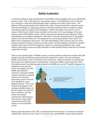
Hydrology Project II: Technical Information 
Prepared for the World Bank by Innovative Hydrology, Inc. 
Page 1 of 2 
Bubbler Explanation 
A common method of stage measurement is the bubbler system equipped with a non-submersible pressure sensor. This is also known as a gas-purge system. A small quantity of air or inert gas (e.g. nitrogen) is allowed to bleed through a pipe or tubing to an orifice in the stream. The pressure of the gas that displaces the liquid in the orifice is then measured by a pressure sensor. The main advantages to a gas purge system are that this technology does not require a stilling well and the large associated cost of installation. Another advantage is the sensor is not in contact with the water, which means any debris in the water won’t cause damage to the most expensive part of the bubbler system, which is the pressure transducer and compressor. Many manufacturers now produce compressors with tanks to store the compressed air for the gradual release of air into the orifice line. The equipment can conveniently operate with a small 12V battery that is charged by solar power. The main disadvantage of this system is the cost of the pressure transducer and gas compressor storage system. The desiccating system that is normally needed to keep water out of the compressor system is a recurring maintenance item. Large capacity desiccating systems are highly desirable in warm humid climates where the air can hold a great deal of water. 
There are two general types of bubbler systems, one that operates continuously and the other that operates just prior and during measurement (non-continuous system). The non-continuous bubble system allows water to feed back up the orifice line, which will need to be expelled and the pressure line stabilized prior to measurement. Continuous bubble systems keep the orifice line under pressure by producing approximately one bubble per second. If rapidly changing river conditions occur and long orifice line lengths exist, this bubble rate should be increased. Continuous bubble systems will process a greater volume of air, thus the desiccating system will need to be replaced at a more frequent interval. This is one of the key advantages to the continuous bubble system, in that the orifice line needs no time to stabilize, since the orifice line remains continuously under pressure. This assures a more stable measurement and for this reason is a more desirable system. 
During recent discussions with CWC a measurement interval less than 15 minutes was desired and possibly 5 minutes or less. There is no reason why a good bubbler system cannot perform
Hydrology Project II: Technical Information 
Prepared for the World Bank by Innovative Hydrology, Inc. 
Page 2 of 2 
measurements every 5 minutes, or even every two minutes. It was suggested that some vendors do not recommend measurement intervals short in duration, which is likely more reflective of the inability of their equipment to perform such measurements, and is certainly a significant challenge for a non-continuous bubbler. Non-continuous bubblers require the orifice line to be purged of water, and then the line needs to be stabilized. This takes time, and in some cases it could take the line minutes to be stabilized from the pneumatic disturbances occurring during the start-up of the compressor on a non-continuous bubbler system. My preference is to use continuous bubbler systems in all applications where a bubbler is warranted. Other common features of top of the line bubbler systems is automatic and manual line purge to clear debris from gathering over the bubbler orifice. These purge capabilities are extremely handy and should be made part of the specification for bubbler systems. 
Bubbler systems work well in open channels as well as reservoirs. With reservoir systems that have a wide range of elevations (> 20 m) the concept of a manifold system utilizing several orifice lines covering 20 meters of range each can be staggered at a single location. For instance, in a reservoir that has 80 m or total elevation changes, one could employ a series of five orifice lines. Orifice lines would be 0-20m, 15-35m, 30-50m, 45-65m, and 60-80m. The orifice line that matches the actual water elevation of the reservoir would be used. As the reservoir elevation moves into a different range, the orifice line connected to the non- submersible sensor would be changed. Of course the operator would need to keep changing the datum for the sensor as the orifice lines are changed. The use of a manifold system allows for the use of a lower range (higher precision) sensor while being able to measure over the entire range of reservoir elevations. 
If the channel is subject to damaging debris, such as rocks tumbling in the channel during high flow, or on unstable bed or channel, the orifice line will be difficult to keep stable. In these circumstances, a bridge mounted Radar would be better. In the event there is no bridge, then the possibility of installing a fortified stilling utilizing a shaft encoder can be effective. A thorough site inspection of the exact reach of channel to be measured is a very important part of determining which measurement technique is most effective.

Bubbler

  • 1.
    Hydrology Project II:Technical Information Prepared for the World Bank by Innovative Hydrology, Inc. Page 1 of 2 Bubbler Explanation A common method of stage measurement is the bubbler system equipped with a non-submersible pressure sensor. This is also known as a gas-purge system. A small quantity of air or inert gas (e.g. nitrogen) is allowed to bleed through a pipe or tubing to an orifice in the stream. The pressure of the gas that displaces the liquid in the orifice is then measured by a pressure sensor. The main advantages to a gas purge system are that this technology does not require a stilling well and the large associated cost of installation. Another advantage is the sensor is not in contact with the water, which means any debris in the water won’t cause damage to the most expensive part of the bubbler system, which is the pressure transducer and compressor. Many manufacturers now produce compressors with tanks to store the compressed air for the gradual release of air into the orifice line. The equipment can conveniently operate with a small 12V battery that is charged by solar power. The main disadvantage of this system is the cost of the pressure transducer and gas compressor storage system. The desiccating system that is normally needed to keep water out of the compressor system is a recurring maintenance item. Large capacity desiccating systems are highly desirable in warm humid climates where the air can hold a great deal of water. There are two general types of bubbler systems, one that operates continuously and the other that operates just prior and during measurement (non-continuous system). The non-continuous bubble system allows water to feed back up the orifice line, which will need to be expelled and the pressure line stabilized prior to measurement. Continuous bubble systems keep the orifice line under pressure by producing approximately one bubble per second. If rapidly changing river conditions occur and long orifice line lengths exist, this bubble rate should be increased. Continuous bubble systems will process a greater volume of air, thus the desiccating system will need to be replaced at a more frequent interval. This is one of the key advantages to the continuous bubble system, in that the orifice line needs no time to stabilize, since the orifice line remains continuously under pressure. This assures a more stable measurement and for this reason is a more desirable system. During recent discussions with CWC a measurement interval less than 15 minutes was desired and possibly 5 minutes or less. There is no reason why a good bubbler system cannot perform
  • 2.
    Hydrology Project II:Technical Information Prepared for the World Bank by Innovative Hydrology, Inc. Page 2 of 2 measurements every 5 minutes, or even every two minutes. It was suggested that some vendors do not recommend measurement intervals short in duration, which is likely more reflective of the inability of their equipment to perform such measurements, and is certainly a significant challenge for a non-continuous bubbler. Non-continuous bubblers require the orifice line to be purged of water, and then the line needs to be stabilized. This takes time, and in some cases it could take the line minutes to be stabilized from the pneumatic disturbances occurring during the start-up of the compressor on a non-continuous bubbler system. My preference is to use continuous bubbler systems in all applications where a bubbler is warranted. Other common features of top of the line bubbler systems is automatic and manual line purge to clear debris from gathering over the bubbler orifice. These purge capabilities are extremely handy and should be made part of the specification for bubbler systems. Bubbler systems work well in open channels as well as reservoirs. With reservoir systems that have a wide range of elevations (> 20 m) the concept of a manifold system utilizing several orifice lines covering 20 meters of range each can be staggered at a single location. For instance, in a reservoir that has 80 m or total elevation changes, one could employ a series of five orifice lines. Orifice lines would be 0-20m, 15-35m, 30-50m, 45-65m, and 60-80m. The orifice line that matches the actual water elevation of the reservoir would be used. As the reservoir elevation moves into a different range, the orifice line connected to the non- submersible sensor would be changed. Of course the operator would need to keep changing the datum for the sensor as the orifice lines are changed. The use of a manifold system allows for the use of a lower range (higher precision) sensor while being able to measure over the entire range of reservoir elevations. If the channel is subject to damaging debris, such as rocks tumbling in the channel during high flow, or on unstable bed or channel, the orifice line will be difficult to keep stable. In these circumstances, a bridge mounted Radar would be better. In the event there is no bridge, then the possibility of installing a fortified stilling utilizing a shaft encoder can be effective. A thorough site inspection of the exact reach of channel to be measured is a very important part of determining which measurement technique is most effective.