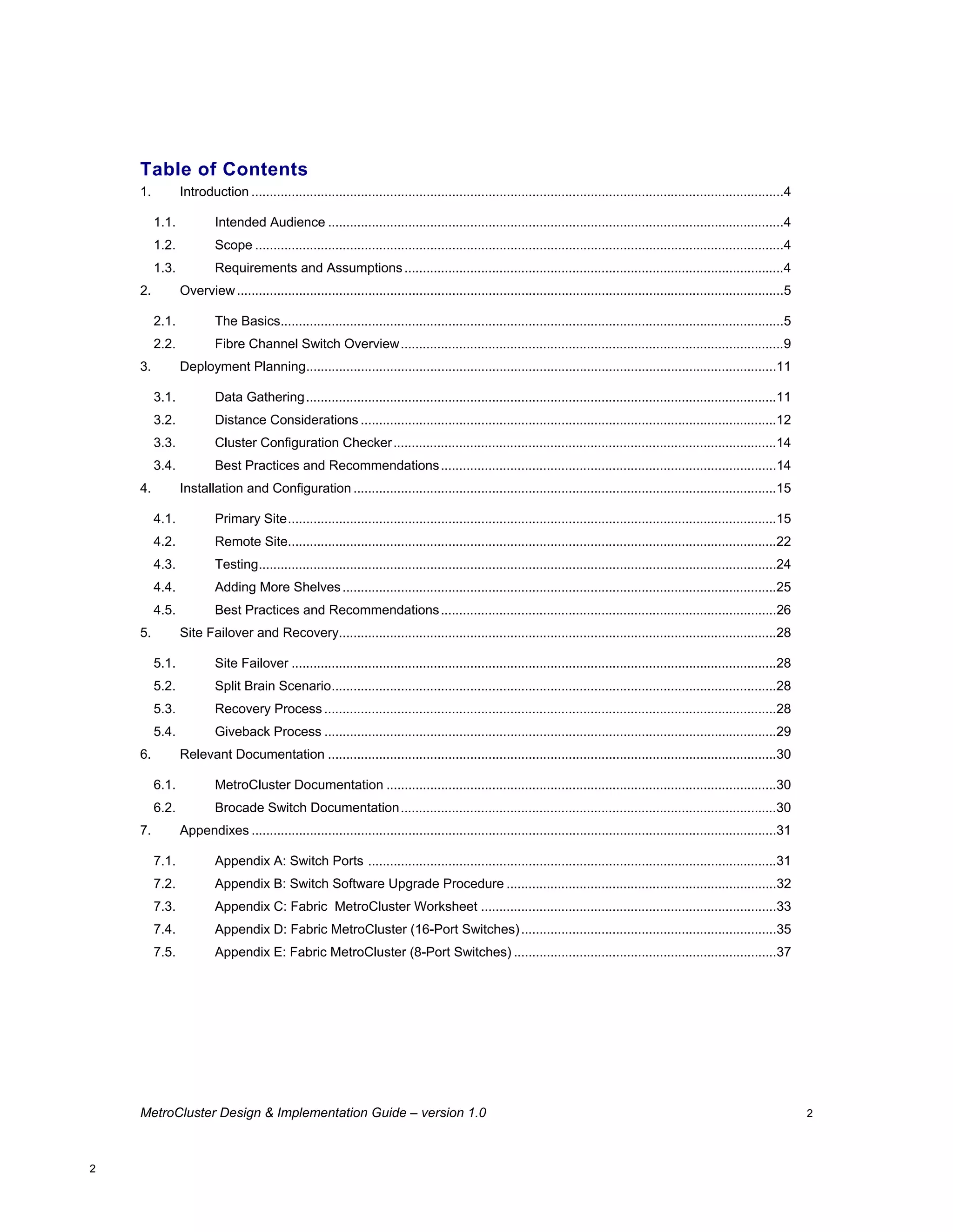
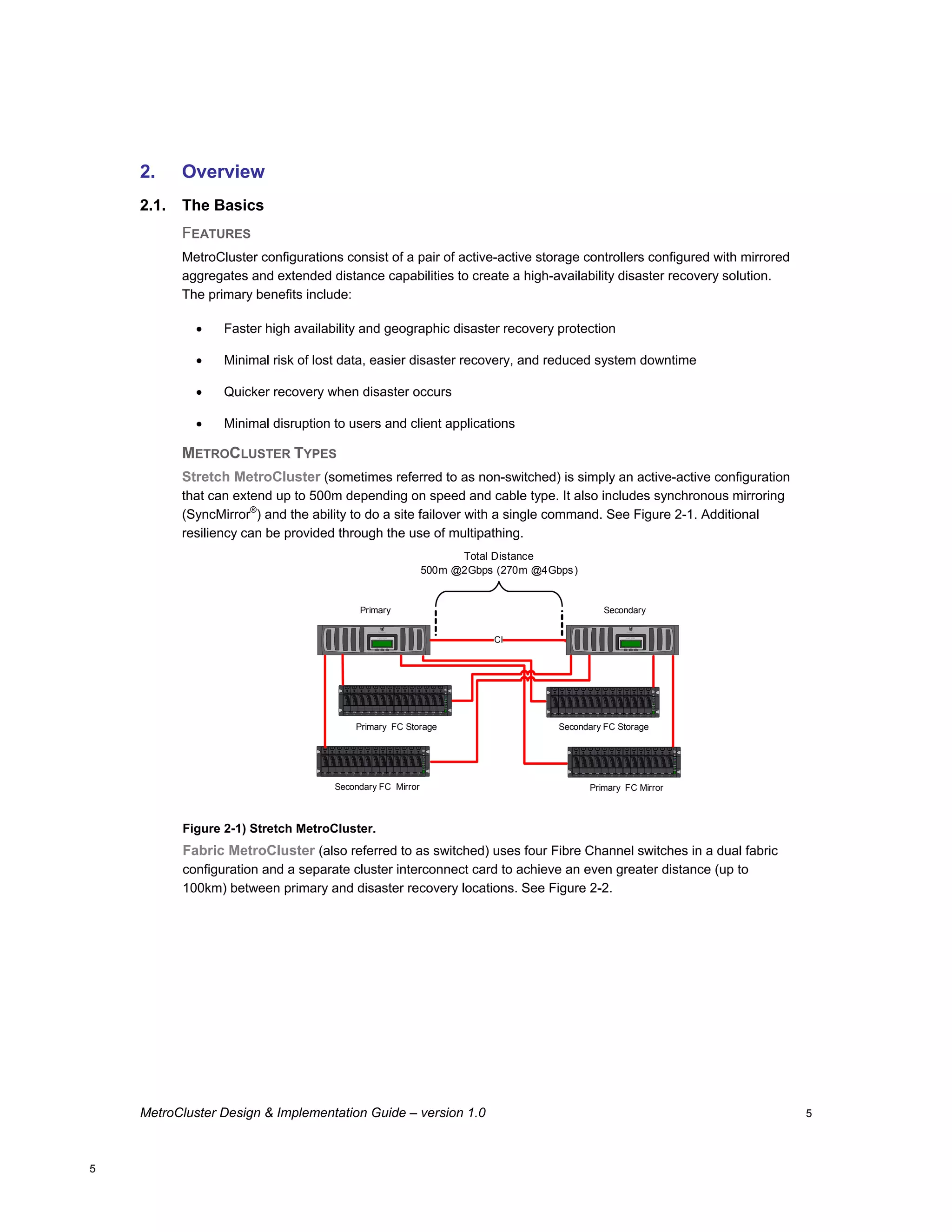
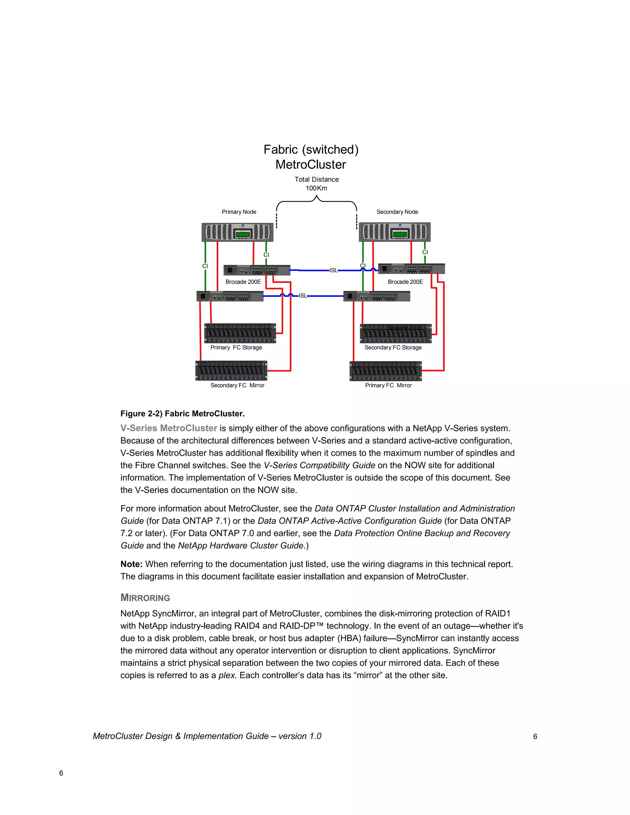
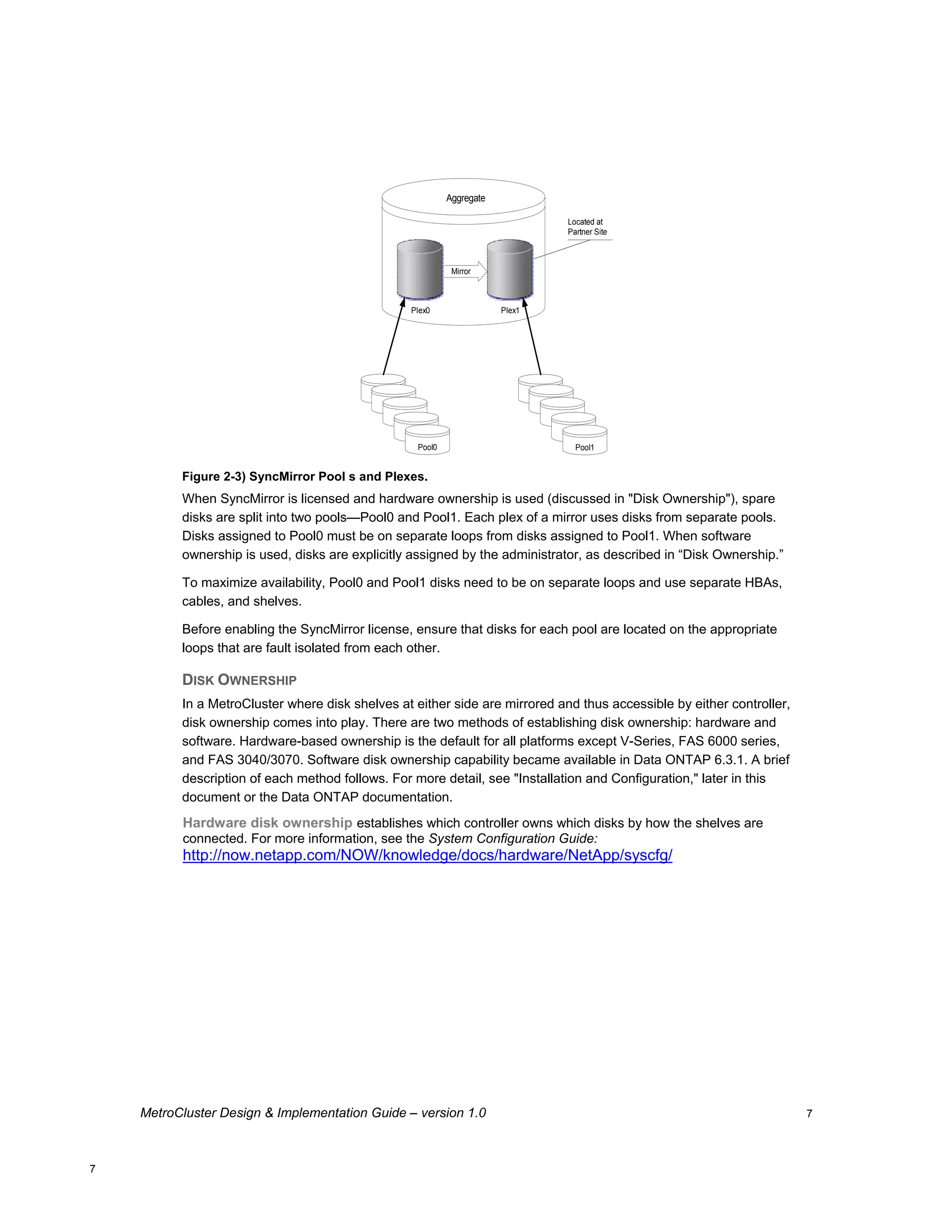
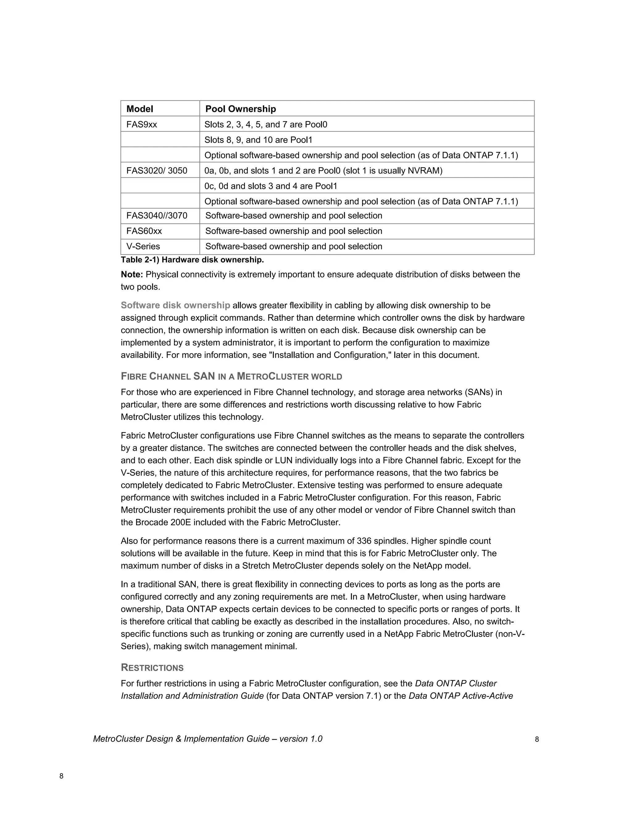
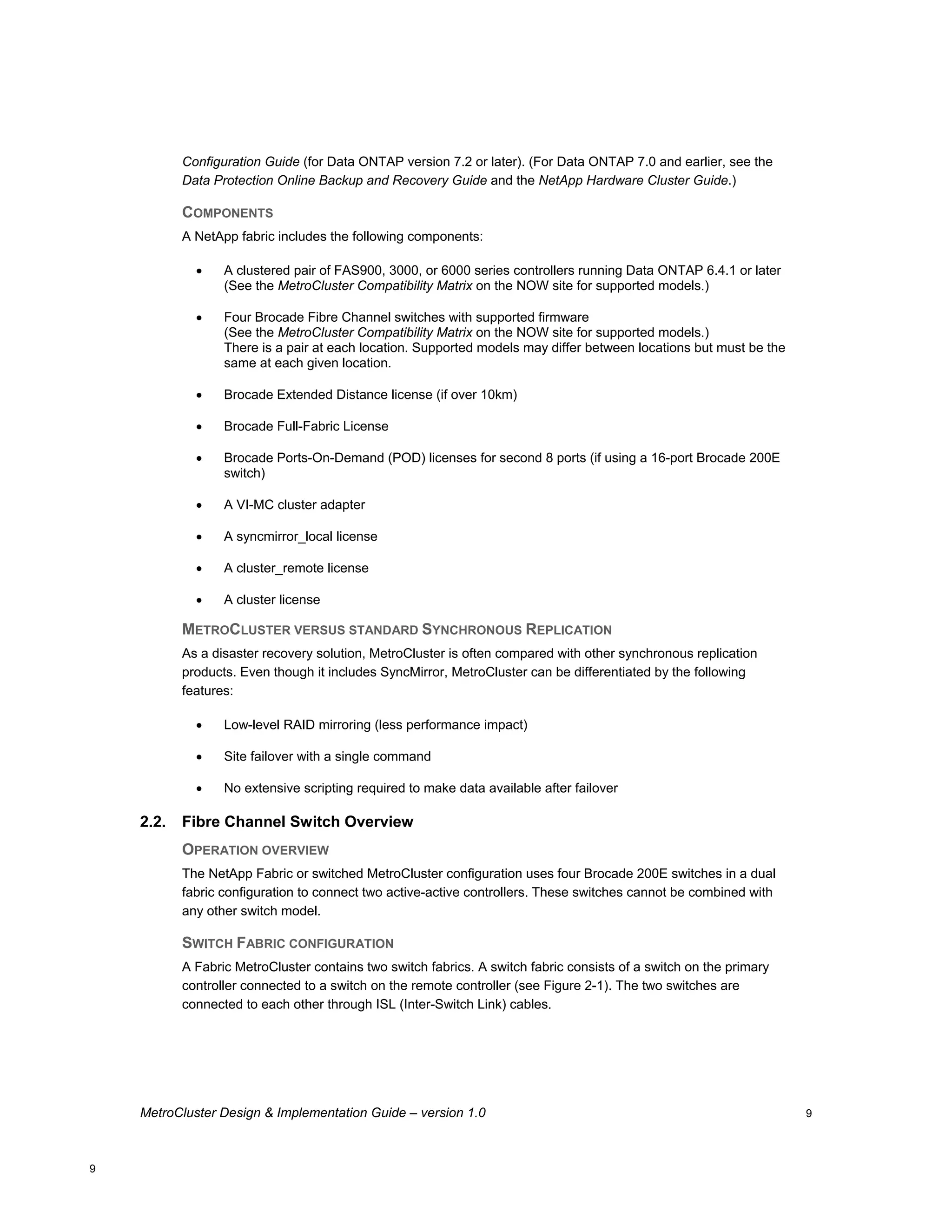
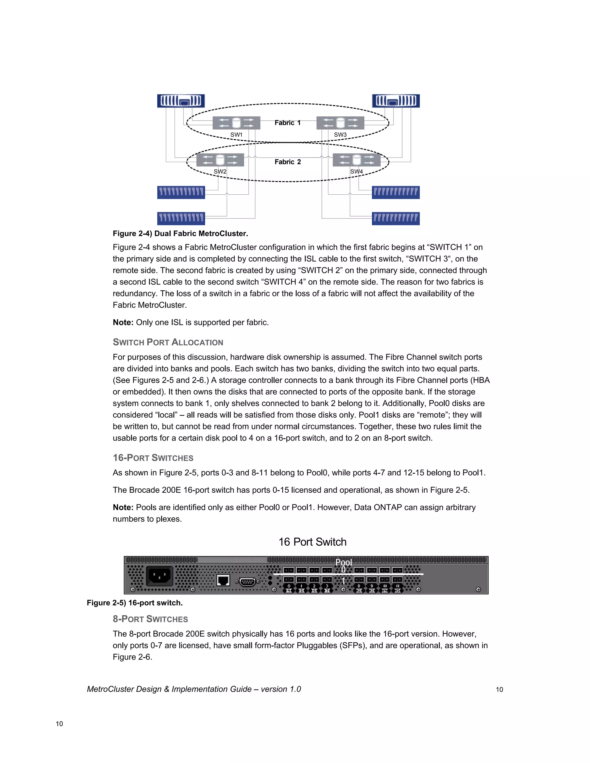
This document provides guidance on architecting and deploying MetroCluster configurations, including an overview of MetroCluster, planning considerations, installation steps, and best practices. It covers stretched, switched, and fabric MetroCluster topologies using NetApp storage and includes configuration examples for 16-port and 8-port Brocade switches. The intended audience is field personnel responsible for MetroCluster implementations.
T Series Core Router Architecture Review (Whitepaper)Juniper Networks
Juniper Networks® T Series Core Routers have been in production since 2002, with the introduction of the Juniper Networks T640 Core Router. Since that time, T Series routers have evolved to maintain an unequivocal industry lead in capacity (slot, chassis, and system) and operational efficiencies in power and usability. Maintaining this standard has in part been possible due to design decisions made with the very first T Series system. The T Series demonstrates how Juniper has evolved its router architecture to achieve substantial technology breakthroughs in packet forwarding performance, bandwidth density, IP service delivery, and system reliability. At the same time, the integrity of the original design has made these breakthroughs possible. Not only do T Series platforms deliver industry-leading scalability, they do so while maintaining feature and software continuity across all routing platforms. Whether deploying a single-chassis or multichassis system, service providers can be assured that the T Series satisfies all networking requirements.
Report on Integrated Modular Avionics (DO-297/ED-124) for Requirement Enginee...Nikhil Dantkale
Considering the integration within Avionics, the Report covers the brief knowledge on Integrated Modular Avionics(IMA) Document DO-297. It also includes the communication bus architectures used in avionics applications, MIL-STD-1553, ARINC 429, and Most advanced AFDX/ARINC 664 Protocol. It covers a brief description on Core Processing Input Output Modules (CPIOMs) computers used in Airbus 380 flight.
How to manage future grid dynamics: system value of Smart Power Generation in...Smart Power Generation
DNV KEMA, a leading energy consultancy, evaluated California Independent System Operator (CAISO) operations and markets for the year 2020 using the PLEXOS™ dispatch simulation platform. This study explores the impact of using Smart Power Generation (SPG) to improve performance of future resource portfolios. The results show that 5.5 GW of SPG capacity (approximately 7% of the capacity for CAISO in 2020) can reduce annual overall variable system costs by 3.9 to 14% (290 million to 1.1 billion dollars), while reducing Carbon Dioxide (CO2) emissions and water consumption.
In a vSphere 5.0 environment, virtual network switches provide connectivity for virtual machines running on VMware® ESXi™ hosts to communicate with each other as well as connectivity to the external physical infrastructure. Network administrators want more visibility into this traffic that is flowing in the virtual infrastructure. This visibility will help them monitor and troubleshoot network issues. VMware vSphere 5.0 introduces two new features in the Distributed Switch that provide the required monitoring and troubleshooting capability to the virtual infrastructure.
As part of the Solar Energy and innovation module, our team Zaid Hani Bani, Cecilia Moramarco, Minh Pham Quang and myself designed, fabricated and tested these solar blinds.
MetaFabric™ Architecture Virtualized Data Center: Design and Implementation G...Juniper Networks
The benefits of virtualization are driving data center operators to rethink their legacy data center networks and look for new ways to reduce costs and improve efficiency in the data center. Moving from a legacy network to a state-of-the-art solution allows you to deploy new applications in seconds rather than days, weeks, or months. If you want to harness the power of virtualization in your data center network, this guide will help you to achieve your goal.
A tale of scale & speed: How the US Navy is enabling software delivery from l...sonjaschweigert1
Rapid and secure feature delivery is a goal across every application team and every branch of the DoD. The Navy’s DevSecOps platform, Party Barge, has achieved:
- Reduction in onboarding time from 5 weeks to 1 day
- Improved developer experience and productivity through actionable findings and reduction of false positives
- Maintenance of superior security standards and inherent policy enforcement with Authorization to Operate (ATO)
Development teams can ship efficiently and ensure applications are cyber ready for Navy Authorizing Officials (AOs). In this webinar, Sigma Defense and Anchore will give attendees a look behind the scenes and demo secure pipeline automation and security artifacts that speed up application ATO and time to production.
We will cover:
- How to remove silos in DevSecOps
- How to build efficient development pipeline roles and component templates
- How to deliver security artifacts that matter for ATO’s (SBOMs, vulnerability reports, and policy evidence)
- How to streamline operations with automated policy checks on container images
The Metaverse and AI: how can decision-makers harness the Metaverse for their...Jen Stirrup
The Metaverse is popularized in science fiction, and now it is becoming closer to being a part of our daily lives through the use of social media and shopping companies. How can businesses survive in a world where Artificial Intelligence is becoming the present as well as the future of technology, and how does the Metaverse fit into business strategy when futurist ideas are developing into reality at accelerated rates? How do we do this when our data isn't up to scratch? How can we move towards success with our data so we are set up for the Metaverse when it arrives?
How can you help your company evolve, adapt, and succeed using Artificial Intelligence and the Metaverse to stay ahead of the competition? What are the potential issues, complications, and benefits that these technologies could bring to us and our organizations? In this session, Jen Stirrup will explain how to start thinking about these technologies as an organisation.
zkStudyClub - Reef: Fast Succinct Non-Interactive Zero-Knowledge Regex ProofsAlex Pruden
This paper presents Reef, a system for generating publicly verifiable succinct non-interactive zero-knowledge proofs that a committed document matches or does not match a regular expression. We describe applications such as proving the strength of passwords, the provenance of email despite redactions, the validity of oblivious DNS queries, and the existence of mutations in DNA. Reef supports the Perl Compatible Regular Expression syntax, including wildcards, alternation, ranges, capture groups, Kleene star, negations, and lookarounds. Reef introduces a new type of automata, Skipping Alternating Finite Automata (SAFA), that skips irrelevant parts of a document when producing proofs without undermining soundness, and instantiates SAFA with a lookup argument. Our experimental evaluation confirms that Reef can generate proofs for documents with 32M characters; the proofs are small and cheap to verify (under a second).
Paper: https://eprint.iacr.org/2023/1886
SAP Sapphire 2024 - ASUG301 building better apps with SAP Fiori.pdfPeter Spielvogel
Building better applications for business users with SAP Fiori.
• What is SAP Fiori and why it matters to you
• How a better user experience drives measurable business benefits
• How to get started with SAP Fiori today
• How SAP Fiori elements accelerates application development
• How SAP Build Code includes SAP Fiori tools and other generative artificial intelligence capabilities
• How SAP Fiori paves the way for using AI in SAP apps
Accelerate your Kubernetes clusters with Varnish CachingThijs Feryn
A presentation about the usage and availability of Varnish on Kubernetes. This talk explores the capabilities of Varnish caching and shows how to use the Varnish Helm chart to deploy it to Kubernetes.
This presentation was delivered at K8SUG Singapore. See https://feryn.eu/presentations/accelerate-your-kubernetes-clusters-with-varnish-caching-k8sug-singapore-28-2024 for more details.
Removing Uninteresting Bytes in Software FuzzingAftab Hussain
Imagine a world where software fuzzing, the process of mutating bytes in test seeds to uncover hidden and erroneous program behaviors, becomes faster and more effective. A lot depends on the initial seeds, which can significantly dictate the trajectory of a fuzzing campaign, particularly in terms of how long it takes to uncover interesting behaviour in your code. We introduce DIAR, a technique designed to speedup fuzzing campaigns by pinpointing and eliminating those uninteresting bytes in the seeds. Picture this: instead of wasting valuable resources on meaningless mutations in large, bloated seeds, DIAR removes the unnecessary bytes, streamlining the entire process.
In this work, we equipped AFL, a popular fuzzer, with DIAR and examined two critical Linux libraries -- Libxml's xmllint, a tool for parsing xml documents, and Binutil's readelf, an essential debugging and security analysis command-line tool used to display detailed information about ELF (Executable and Linkable Format). Our preliminary results show that AFL+DIAR does not only discover new paths more quickly but also achieves higher coverage overall. This work thus showcases how starting with lean and optimized seeds can lead to faster, more comprehensive fuzzing campaigns -- and DIAR helps you find such seeds.
- These are slides of the talk given at IEEE International Conference on Software Testing Verification and Validation Workshop, ICSTW 2022.
Encryption in Microsoft 365 - ExpertsLive Netherlands 2024Albert Hoitingh
In this session I delve into the encryption technology used in Microsoft 365 and Microsoft Purview. Including the concepts of Customer Key and Double Key Encryption.
GDG Cloud Southlake #33: Boule & Rebala: Effective AppSec in SDLC using Deplo...James Anderson
Effective Application Security in Software Delivery lifecycle using Deployment Firewall and DBOM
The modern software delivery process (or the CI/CD process) includes many tools, distributed teams, open-source code, and cloud platforms. Constant focus on speed to release software to market, along with the traditional slow and manual security checks has caused gaps in continuous security as an important piece in the software supply chain. Today organizations feel more susceptible to external and internal cyber threats due to the vast attack surface in their applications supply chain and the lack of end-to-end governance and risk management.
The software team must secure its software delivery process to avoid vulnerability and security breaches. This needs to be achieved with existing tool chains and without extensive rework of the delivery processes. This talk will present strategies and techniques for providing visibility into the true risk of the existing vulnerabilities, preventing the introduction of security issues in the software, resolving vulnerabilities in production environments quickly, and capturing the deployment bill of materials (DBOM).
Speakers:
Bob Boule
Robert Boule is a technology enthusiast with PASSION for technology and making things work along with a knack for helping others understand how things work. He comes with around 20 years of solution engineering experience in application security, software continuous delivery, and SaaS platforms. He is known for his dynamic presentations in CI/CD and application security integrated in software delivery lifecycle.
Gopinath Rebala
Gopinath Rebala is the CTO of OpsMx, where he has overall responsibility for the machine learning and data processing architectures for Secure Software Delivery. Gopi also has a strong connection with our customers, leading design and architecture for strategic implementations. Gopi is a frequent speaker and well-known leader in continuous delivery and integrating security into software delivery.
Le nuove frontiere dell'AI nell'RPA con UiPath Autopilot™UiPathCommunity
In questo evento online gratuito, organizzato dalla Community Italiana di UiPath, potrai esplorare le nuove funzionalità di Autopilot, il tool che integra l'Intelligenza Artificiale nei processi di sviluppo e utilizzo delle Automazioni.
📕 Vedremo insieme alcuni esempi dell'utilizzo di Autopilot in diversi tool della Suite UiPath:
Autopilot per Studio Web
Autopilot per Studio
Autopilot per Apps
Clipboard AI
GenAI applicata alla Document Understanding
👨🏫👨💻 Speakers:
Stefano Negro, UiPath MVPx3, RPA Tech Lead @ BSP Consultant
Flavio Martinelli, UiPath MVP 2023, Technical Account Manager @UiPath
Andrei Tasca, RPA Solutions Team Lead @NTT Data
Why You Should Replace Windows 11 with Nitrux Linux 3.5.0 for enhanced perfor...SOFTTECHHUB
The choice of an operating system plays a pivotal role in shaping our computing experience. For decades, Microsoft's Windows has dominated the market, offering a familiar and widely adopted platform for personal and professional use. However, as technological advancements continue to push the boundaries of innovation, alternative operating systems have emerged, challenging the status quo and offering users a fresh perspective on computing.
One such alternative that has garnered significant attention and acclaim is Nitrux Linux 3.5.0, a sleek, powerful, and user-friendly Linux distribution that promises to redefine the way we interact with our devices. With its focus on performance, security, and customization, Nitrux Linux presents a compelling case for those seeking to break free from the constraints of proprietary software and embrace the freedom and flexibility of open-source computing.
The Art of the Pitch: WordPress Relationships and SalesLaura Byrne
Clients don’t know what they don’t know. What web solutions are right for them? How does WordPress come into the picture? How do you make sure you understand scope and timeline? What do you do if sometime changes?
All these questions and more will be explored as we talk about matching clients’ needs with what your agency offers without pulling teeth or pulling your hair out. Practical tips, and strategies for successful relationship building that leads to closing the deal.
In his public lecture, Christian Timmerer provides insights into the fascinating history of video streaming, starting from its humble beginnings before YouTube to the groundbreaking technologies that now dominate platforms like Netflix and ORF ON. Timmerer also presents provocative contributions of his own that have significantly influenced the industry. He concludes by looking at future challenges and invites the audience to join in a discussion.
Essentials of Automations: The Art of Triggers and Actions in FMESafe Software
In this second installment of our Essentials of Automations webinar series, we’ll explore the landscape of triggers and actions, guiding you through the nuances of authoring and adapting workspaces for seamless automations. Gain an understanding of the full spectrum of triggers and actions available in FME, empowering you to enhance your workspaces for efficient automation.
We’ll kick things off by showcasing the most commonly used event-based triggers, introducing you to various automation workflows like manual triggers, schedules, directory watchers, and more. Plus, see how these elements play out in real scenarios.
Whether you’re tweaking your current setup or building from the ground up, this session will arm you with the tools and insights needed to transform your FME usage into a powerhouse of productivity. Join us to discover effective strategies that simplify complex processes, enhancing your productivity and transforming your data management practices with FME. Let’s turn complexity into clarity and make your workspaces work wonders!
Climate Impact of Software Testing at Nordic Testing DaysKari Kakkonen
My slides at Nordic Testing Days 6.6.2024
Climate impact / sustainability of software testing discussed on the talk. ICT and testing must carry their part of global responsibility to help with the climat warming. We can minimize the carbon footprint but we can also have a carbon handprint, a positive impact on the climate. Quality characteristics can be added with sustainability, and then measured continuously. Test environments can be used less, and in smaller scale and on demand. Test techniques can be used in optimizing or minimizing number of tests. Test automation can be used to speed up testing.
Observability Concepts EVERY Developer Should Know -- DeveloperWeek Europe.pdfPaige Cruz
Monitoring and observability aren’t traditionally found in software curriculums and many of us cobble this knowledge together from whatever vendor or ecosystem we were first introduced to and whatever is a part of your current company’s observability stack.
While the dev and ops silo continues to crumble….many organizations still relegate monitoring & observability as the purview of ops, infra and SRE teams. This is a mistake - achieving a highly observable system requires collaboration up and down the stack.
I, a former op, would like to extend an invitation to all application developers to join the observability party will share these foundational concepts to build on:
Observability Concepts EVERY Developer Should Know -- DeveloperWeek Europe.pdf
Brocade200 E Metro Cluster Design
1. MetroCluster Design and Implementation Guide
Jim Lanson, Network Appliance, Inc.
May, 2007 | TR-3548
Abstract
This document is intended to serve as a guide for architecting and deploying MetroCluster in a customer
environment. This design and implementation guide describes the basic MetroCluster architecture,
considerations for deployment, and best practices. As always, please refer to the latest technical
publications on the NOW™ (NetApp on the Web) site for specific updates on processes, Data ONTAP®
command syntax, and the latest requirements, issues, and limitations. This document is intended for field
personnel who require assistance in architecting and deploying a MetroCluster solution.
2. Table of Contents
1. Introduction ..................................................................................................................................................4
1.1. Intended Audience .............................................................................................................................4
1.2. Scope .................................................................................................................................................4
1.3. Requirements and Assumptions ........................................................................................................4
2. Overview ......................................................................................................................................................5
2.1. The Basics..........................................................................................................................................5
2.2. Fibre Channel Switch Overview.........................................................................................................9
3. Deployment Planning.................................................................................................................................11
3.1. Data Gathering.................................................................................................................................11
3.2. Distance Considerations ..................................................................................................................12
3.3. Cluster Configuration Checker.........................................................................................................14
3.4. Best Practices and Recommendations ............................................................................................14
4. Installation and Configuration ....................................................................................................................15
4.1. Primary Site......................................................................................................................................15
4.2. Remote Site......................................................................................................................................22
4.3. Testing..............................................................................................................................................24
4.4. Adding More Shelves .......................................................................................................................25
4.5. Best Practices and Recommendations ............................................................................................26
5. Site Failover and Recovery........................................................................................................................28
5.1. Site Failover .....................................................................................................................................28
5.2. Split Brain Scenario..........................................................................................................................28
5.3. Recovery Process ............................................................................................................................28
5.4. Giveback Process ............................................................................................................................29
6. Relevant Documentation ...........................................................................................................................30
6.1. MetroCluster Documentation ...........................................................................................................30
6.2. Brocade Switch Documentation.......................................................................................................30
7. Appendixes ................................................................................................................................................31
7.1. Appendix A: Switch Ports ................................................................................................................31
7.2. Appendix B: Switch Software Upgrade Procedure ..........................................................................32
7.3. Appendix C: Fabric MetroCluster Worksheet .................................................................................33
7.4. Appendix D: Fabric MetroCluster (16-Port Switches) ......................................................................35
7.5. Appendix E: Fabric MetroCluster (8-Port Switches) ........................................................................37
MetroCluster Design & Implementation Guide – version 1.0 2
2
3. Figures and Tables
Figure 2-1) Stretch MetroCluster. ...........................................................................................................................5
Figure 2-2) Fabric MetroCluster. ............................................................................................................................6
Figure 2-3) SyncMirror............................................................................................................................................7
Table 2-1) Hardware disk ownership......................................................................................................................8
Figure 2-4) Dual Fabric MetroCluster. ..................................................................................................................10
Figure 2-5) 16-port switch.....................................................................................................................................10
Figure 2-6) 8-port switch.......................................................................................................................................11
Figure 4- 1) Primary node cabling – appliance to switches..................................................................................19
Figure 4-2) Primary node cabling – disk shelf to switch.......................................................................................20
Figure 4-3) Remote node – appliance to switch...................................................................................................23
Figure 4-4) Remote node cabling – disk shelf to switch.......................................................................................24
Figure 4-5) 16-port switch port assignments. .......................................................................................................25
Figure 4-6) 8-port switch port assignments. .........................................................................................................25
Figure 4-7a) Adding disk shelves to primary node. ..............................................................................................26
Figure 4-7b) Adding disk shelves to remote node................................................................................................26
MetroCluster Design & Implementation Guide – version 1.0 3
3
4. 1. Introduction
1.1. Intended Audience
The information in this document is intended for field personnel and administrators who are responsible
for architecting and deploying successful MetroCluster high-availability and disaster-recovery
configurations. A brief overview of MetroCluster is presented in order to establish baseline knowledge
before discussing implementation planning, installation, configuration, and operation.
1.2. Scope
This document covers the following MetroCluster configurations:
• Stretched or non-switched MetroCluster (NetApp storage)
• Fabric or switched MetroCluster (NetApp Storage)
Topics that apply only to non-switched MetroCluster refer to Stretch MetroCluster.
Topics that are specific to NetApp storage-based fabric MetroCluster refer to Fabric MetroCluster.
Topics that apply to all configurations refer simply to MetroCluster.
Other than a short description, V-Series MetroCluster is not covered in this document.
This document refers mostly to Fabric MetroCluster, because Fabric MetroCluster configurations
introduce an increased level of complexity in design and implementation. To many, Stretch MetroCluster
is simply an active-active configuration with longer cables and mirroring. The introduction of Fibre
Channel switches and longer distances requires much more consideration and discussion. The
operational sections (creating mirrors, forced takeover, etc.) apply to both.
1.3. Requirements and Assumptions
For the methods and procedures described in this document to be useful to the reader, the following
assumptions are made:
• The reader has at least basic Network Appliance administration skills and has administrative
access to the storage system via the command-line interface.
• The reader has a full understanding of clustering as it applies to the NetApp storage controller
environment.
• The reader has at least a basic understanding of Fibre Channel switch technology and operation,
along with access to the switches via command line.
• In the examples in this report, all administrative commands are performed at the storage system or
Fibre Channel switch command line.
MetroCluster Design & Implementation Guide – version 1.0 4
4
5. 2. Overview
2.1. The Basics
FEATURES
MetroCluster configurations consist of a pair of active-active storage controllers configured with mirrored
aggregates and extended distance capabilities to create a high-availability disaster recovery solution.
The primary benefits include:
• Faster high availability and geographic disaster recovery protection
• Minimal risk of lost data, easier disaster recovery, and reduced system downtime
• Quicker recovery when disaster occurs
• Minimal disruption to users and client applications
METROCLUSTER TYPES
Stretch MetroCluster (sometimes referred to as non-switched) is simply an active-active configuration
that can extend up to 500m depending on speed and cable type. It also includes synchronous mirroring
(SyncMirror®) and the ability to do a site failover with a single command. See Figure 2-1. Additional
resiliency can be provided through the use of multipathing.
Total Distance
500m @2Gbps (270m @4Gbps )
Primary Secondary
NetApp NetApp
CI
FAS 3020 FAS 3020
activity status power activity status power
DS 14
DS 14
MK2
Network Appl ianc e NetworkAppliance Net work Applia nce Network Appli anc e NetworkAppliance NetworkApplia nce Network Applia nc e NetworkAppliance NetworkApplia nce NetworkAppliance NetworkAppliance NetworkAppliance NetworkAppliance NetworkAppliance MK2
AT NetworkApplia nce NetworkAppliance NetworkAppliance NetworkAppliance NetworkAppliance NetworkAppliance NetworkAppliance NetworkAppliance NetworkAppliance Network Appl ianc e NetworkAppliance NetworkAppliance Network Appli anc e Network Appl ianc e
AT
Pow er
Pow er
F ault
F ault
Module A
Module A
Module B
Module B
Sys tem
Sys tem
Shelf ID
Shelf ID
212A 212A 212A 212A 212A 212A 212A 212A 212A 212A 212A 212A 212A 212A
13 12 11 10 09 08 07 06 05 04 03 02 01 00 212A 212A 212A 212A 212A 212A 212A 212A 212A 212A 212A 212A 212A 212A
13 12 11 10 09 08 07 06 05 04 03 02 01 00
Primary FC Storage Secondary FC Storage
DS 14
DS 14
MK2
MK2
NetworkAppliance Network Appl ianc e NetworkAppliance NetworkAppliance Network Appl ianc e NetworkAppliance NetworkAppliance Network Appli anc e Network Appl ianc e Net work Applia nce Network Applia nc e Network Appl ianc e NetworkAppliance Net work Applia nce
NetworkAppliance NetworkAppliance NetworkAppliance NetworkAppliance Network Appl ianc e NetworkAppliance NetworkAppliance Network Appl ianc e NetworkAppliance Net work Applia nce Network Appli anc e NetworkAppliance Net work Applia nce Network Applia nc e
AT
AT
P ower
P ower
Fau lt
Fau lt
Module A
Module A
Module B
Module B
S ystem
S ystem
Shelf ID
Shelf ID
212A 212A 212A 212A 212A 212A 212A 212A 212A 212A 212A 212A 212A 212A
13 12 11 10 09 08 07 06 05 04 03 02 01 00
13 12 11 10 09 08 07 06 05 04 03 02 01 00
Secondary FC Mirror Primary FC Mirror
Figure 2-1) Stretch MetroCluster.
Fabric MetroCluster (also referred to as switched) uses four Fibre Channel switches in a dual fabric
configuration and a separate cluster interconnect card to achieve an even greater distance (up to
100km) between primary and disaster recovery locations. See Figure 2-2.
MetroCluster Design & Implementation Guide – version 1.0 5
5
6. Fabric (switched)
MetroCluster
Total Distance
100Km
Primary Node Secondary Node
NetApp
NetApp
FAS 3020
FAS 3020
activity status power
activity status po r
we
CI
CI
CI
CI
ISL
Brocade 200E Brocade 200E
ISL
Brocade 200E
DS14 DS 14
M K2
MK2
NetworkA pplia nce Net workAppliance Net workAppliance Net workAppliance NetworkA ppliance NetworkA ppliance NetworkA ppliance Network Appliance Network Appliance Ne tworkApplianc e Ne tworkApplianc e Ne tworkApplianc e NetworkA ppliance NetworkA ppliance
Netw orkAppliance N etworkAppliance N etworkAppliance N etworkAppliance Netw orkAppliance Netw orkAppliance Netw orkAppliance Ne tworkAppliance Ne tworkAppliance NetworkA ppliance NetworkA ppliance NetworkA ppliance Net workAppliance Net workAppliance
AT
AT
P ow er
Power
Fault
Fault
Module A
Module A
Module B Module B
S ystem Sys tem
Shelf ID Shelf ID
212A 212A 212A 212A 212A 212A 212A 212A 212A 212A 212A 212A 212A 212A 212A 212A 212A 212A 212A 212A 212A 212A 212A 212A 212A 212A 212A 212A
13 12 11 10 09 08 07 06 05 04 03 02 01 00 13 12 11 10 09 08 07 06 05 04 03 02 01 00
Primary FC Storage Secondary FC Storage
DS14 DS14
MK2
MK2
Netw ork Appliance Ne tworkAppliance Ne tworkAppliance Ne tworkAppliance Network Appliance Network Appliance Network Appliance Netw orkAppliance Netw orkAppliance N etworkAppliance N etworkAppliance N etworkAppliance Netw orkAppliance Netw orkAppliance
N etworkA ppl iance N etworkA ppl iance Netw orkAppliance N etworkA ppliance N etworkA ppliance Net workAppliance N etworkA ppliance Ne tworkAppliance Netw orkApplianc e Netw orkApplianc e N etworkA pplia nce Netw orkAppliance Netw orkAppliance N etworkA ppl iance
AT
AT
P ow er
P ower
Fault
Fault
Module A
Module A
Module B
Module B
System
System
Shelf ID
Shelf ID
212A 212A 212A 212A 212A 212A 212A 212A 212A 212A 212A 212A 212A 212A
13 12 11 10 09 08 07 06 05 04 03 02 01 00
13 12 11 10 09 08 07 06 05 04 03 02 01 00
Secondary FC Mirror Primary FC Mirror
Figure 2-2) Fabric MetroCluster.
V-Series MetroCluster is simply either of the above configurations with a NetApp V-Series system.
Because of the architectural differences between V-Series and a standard active-active configuration,
V-Series MetroCluster has additional flexibility when it comes to the maximum number of spindles and
the Fibre Channel switches. See the V-Series Compatibility Guide on the NOW site for additional
information. The implementation of V-Series MetroCluster is outside the scope of this document. See
the V-Series documentation on the NOW site.
For more information about MetroCluster, see the Data ONTAP Cluster Installation and Administration
Guide (for Data ONTAP 7.1) or the Data ONTAP Active-Active Configuration Guide (for Data ONTAP
7.2 or later). (For Data ONTAP 7.0 and earlier, see the Data Protection Online Backup and Recovery
Guide and the NetApp Hardware Cluster Guide.)
Note: When referring to the documentation just listed, use the wiring diagrams in this technical report.
The diagrams in this document facilitate easier installation and expansion of MetroCluster.
MIRRORING
NetApp SyncMirror, an integral part of MetroCluster, combines the disk-mirroring protection of RAID1
with NetApp industry-leading RAID4 and RAID-DP™ technology. In the event of an outage—whether it's
due to a disk problem, cable break, or host bus adapter (HBA) failure—SyncMirror can instantly access
the mirrored data without any operator intervention or disruption to client applications. SyncMirror
maintains a strict physical separation between the two copies of your mirrored data. Each of these
copies is referred to as a plex. Each controller’s data has its “mirror” at the other site.
MetroCluster Design & Implementation Guide – version 1.0 6
6
7. Aggregate
Located at
Partner Site
Mirror
Plex0 Plex1
Pool0 Pool1
Figure 2-3) SyncMirror Pool s and Plexes.
When SyncMirror is licensed and hardware ownership is used (discussed in quot;Disk Ownershipquot;), spare
disks are split into two pools—Pool0 and Pool1. Each plex of a mirror uses disks from separate pools.
Disks assigned to Pool0 must be on separate loops from disks assigned to Pool1. When software
ownership is used, disks are explicitly assigned by the administrator, as described in “Disk Ownership.”
To maximize availability, Pool0 and Pool1 disks need to be on separate loops and use separate HBAs,
cables, and shelves.
Before enabling the SyncMirror license, ensure that disks for each pool are located on the appropriate
loops that are fault isolated from each other.
DISK OWNERSHIP
In a MetroCluster where disk shelves at either side are mirrored and thus accessible by either controller,
disk ownership comes into play. There are two methods of establishing disk ownership: hardware and
software. Hardware-based ownership is the default for all platforms except V-Series, FAS 6000 series,
and FAS 3040/3070. Software disk ownership capability became available in Data ONTAP 6.3.1. A brief
description of each method follows. For more detail, see quot;Installation and Configuration,quot; later in this
document or the Data ONTAP documentation.
Hardware disk ownership establishes which controller owns which disks by how the shelves are
connected. For more information, see the System Configuration Guide:
http://now.netapp.com/NOW/knowledge/docs/hardware/NetApp/syscfg/
MetroCluster Design & Implementation Guide – version 1.0 7
7
8. Model Pool Ownership
FAS9xx Slots 2, 3, 4, 5, and 7 are Pool0
Slots 8, 9, and 10 are Pool1
Optional software-based ownership and pool selection (as of Data ONTAP 7.1.1)
FAS3020/ 3050 0a, 0b, and slots 1 and 2 are Pool0 (slot 1 is usually NVRAM)
0c, 0d and slots 3 and 4 are Pool1
Optional software-based ownership and pool selection (as of Data ONTAP 7.1.1)
FAS3040//3070 Software-based ownership and pool selection
FAS60xx Software-based ownership and pool selection
V-Series Software-based ownership and pool selection
Table 2-1) Hardware disk ownership.
Note: Physical connectivity is extremely important to ensure adequate distribution of disks between the
two pools.
Software disk ownership allows greater flexibility in cabling by allowing disk ownership to be
assigned through explicit commands. Rather than determine which controller owns the disk by hardware
connection, the ownership information is written on each disk. Because disk ownership can be
implemented by a system administrator, it is important to perform the configuration to maximize
availability. For more information, see quot;Installation and Configuration,quot; later in this document.
FIBRE CHANNEL SAN IN A METROCLUSTER WORLD
For those who are experienced in Fibre Channel technology, and storage area networks (SANs) in
particular, there are some differences and restrictions worth discussing relative to how Fabric
MetroCluster utilizes this technology.
Fabric MetroCluster configurations use Fibre Channel switches as the means to separate the controllers
by a greater distance. The switches are connected between the controller heads and the disk shelves,
and to each other. Each disk spindle or LUN individually logs into a Fibre Channel fabric. Except for the
V-Series, the nature of this architecture requires, for performance reasons, that the two fabrics be
completely dedicated to Fabric MetroCluster. Extensive testing was performed to ensure adequate
performance with switches included in a Fabric MetroCluster configuration. For this reason, Fabric
MetroCluster requirements prohibit the use of any other model or vendor of Fibre Channel switch than
the Brocade 200E included with the Fabric MetroCluster.
Also for performance reasons there is a current maximum of 336 spindles. Higher spindle count
solutions will be available in the future. Keep in mind that this is for Fabric MetroCluster only. The
maximum number of disks in a Stretch MetroCluster depends solely on the NetApp model.
In a traditional SAN, there is great flexibility in connecting devices to ports as long as the ports are
configured correctly and any zoning requirements are met. In a MetroCluster, when using hardware
ownership, Data ONTAP expects certain devices to be connected to specific ports or ranges of ports. It
is therefore critical that cabling be exactly as described in the installation procedures. Also, no switch-
specific functions such as trunking or zoning are currently used in a NetApp Fabric MetroCluster (non-V-
Series), making switch management minimal.
RESTRICTIONS
For further restrictions in using a Fabric MetroCluster configuration, see the Data ONTAP Cluster
Installation and Administration Guide (for Data ONTAP version 7.1) or the Data ONTAP Active-Active
MetroCluster Design & Implementation Guide – version 1.0 8
8
9. Configuration Guide (for Data ONTAP version 7.2 or later). (For Data ONTAP 7.0 and earlier, see the
Data Protection Online Backup and Recovery Guide and the NetApp Hardware Cluster Guide.)
COMPONENTS
A NetApp fabric includes the following components:
• A clustered pair of FAS900, 3000, or 6000 series controllers running Data ONTAP 6.4.1 or later
(See the MetroCluster Compatibility Matrix on the NOW site for supported models.)
• Four Brocade Fibre Channel switches with supported firmware
(See the MetroCluster Compatibility Matrix on the NOW site for supported models.)
There is a pair at each location. Supported models may differ between locations but must be the
same at each given location.
• Brocade Extended Distance license (if over 10km)
• Brocade Full-Fabric License
• Brocade Ports-On-Demand (POD) licenses for second 8 ports (if using a 16-port Brocade 200E
switch)
• A VI-MC cluster adapter
• A syncmirror_local license
• A cluster_remote license
• A cluster license
METROCLUSTER VERSUS STANDARD SYNCHRONOUS REPLICATION
As a disaster recovery solution, MetroCluster is often compared with other synchronous replication
products. Even though it includes SyncMirror, MetroCluster can be differentiated by the following
features:
• Low-level RAID mirroring (less performance impact)
• Site failover with a single command
• No extensive scripting required to make data available after failover
2.2. Fibre Channel Switch Overview
OPERATION OVERVIEW
The NetApp Fabric or switched MetroCluster configuration uses four Brocade 200E switches in a dual
fabric configuration to connect two active-active controllers. These switches cannot be combined with
any other switch model.
SWITCH FABRIC CONFIGURATION
A Fabric MetroCluster contains two switch fabrics. A switch fabric consists of a switch on the primary
controller connected to a switch on the remote controller (see Figure 2-1). The two switches are
connected to each other through ISL (Inter-Switch Link) cables.
MetroCluster Design & Implementation Guide – version 1.0 9
9
10. Fabric 1
SW1 SW3
Fabric 2
SW2 SW4
Figure 2-4) Dual Fabric MetroCluster.
Figure 2-4 shows a Fabric MetroCluster configuration in which the first fabric begins at “SWITCH 1” on
the primary side and is completed by connecting the ISL cable to the first switch, “SWITCH 3“, on the
remote side. The second fabric is created by using “SWITCH 2” on the primary side, connected through
a second ISL cable to the second switch “SWITCH 4” on the remote side. The reason for two fabrics is
redundancy. The loss of a switch in a fabric or the loss of a fabric will not affect the availability of the
Fabric MetroCluster.
Note: Only one ISL is supported per fabric.
SWITCH PORT ALLOCATION
For purposes of this discussion, hardware disk ownership is assumed. The Fibre Channel switch ports
are divided into banks and pools. Each switch has two banks, dividing the switch into two equal parts.
(See Figures 2-5 and 2-6.) A storage controller connects to a bank through its Fibre Channel ports (HBA
or embedded). It then owns the disks that are connected to ports of the opposite bank. If the storage
system connects to bank 1, only shelves connected to bank 2 belong to it. Additionally, Pool0 disks are
considered “local” – all reads will be satisfied from those disks only. Pool1 disks are “remote”; they will
be written to, but cannot be read from under normal circumstances. Together, these two rules limit the
usable ports for a certain disk pool to 4 on a 16-port switch, and to 2 on an 8-port switch.
16-PORT SWITCHES
As shown in Figure 2-5, ports 0-3 and 8-11 belong to Pool0, while ports 4-7 and 12-15 belong to Pool1.
The Brocade 200E 16-port switch has ports 0-15 licensed and operational, as shown in Figure 2-5.
Note: Pools are identified only as either Pool0 or Pool1. However, Data ONTAP can assign arbitrary
numbers to plexes.
16 Port Switch
Pool
0
1
Figure 2-5) 16-port switch.
8-PORT SWITCHES
The 8-port Brocade 200E switch physically has 16 ports and looks like the 16-port version. However,
only ports 0-7 are licensed, have small form-factor Pluggables (SFPs), and are operational, as shown in
Figure 2-6.
MetroCluster Design & Implementation Guide – version 1.0 10
10
11. Note: Do not install SFPs in unused ports 8-15. This might cause Data ONTAP to operate as if it's a 16-
port switch and erroneously assign banks, quadrants, and pools to unused ports.
As shown in Figure 2-6, ports 0-1 and 4-5 belong to Pool0, while ports 2-3 and 6-7 belong to Pool1.
8 Port Switch
Pool 0 Pool 1
Figure 2-6) 8-port switch.
LICENSES
A number of licenses are required for the Fibre Channel switches. When ordered with a Fabric
MetroCluster configuration, the switches should include all necessary licenses. For reference, they are:
• Full Fabric License
• Extended Distance License (if over 10km)
• Brocade Ports-On-Demand (POD) licenses for second 8 ports (if using a 16-port Brocade 200E
switch)
3. Deployment Planning
3.1. Data Gathering
CUSTOMER REQUIREMENTS
To facilitate a successful MetroCluster installation, the following information should be gathered early
on.
ENVIRONMENTAL
Distance between the primary and remote sites. This information is necessary to determine which type
of MetroCluster is appropriate, or even whether either version is appropriate. In calculating the effective
distance, factors such as cable type, speed, and number of patch panels must be considered. (See
Section 3.2, quot;Distance Considerations.quot;) Although NetApp recommends that dedicated dark fiber be
used for a MetroCluster, WDM devices are supported. Refer to the Brocade Compatibility Guide at
www.brocade.com for supported devices.
SETUP
Gather the following items before you begin any MetroCluster installation:
NetApp and Fibre Channel switch licenses
Hostnames and IP addresses for each of the nodes and the Fibre Channel switches
Brocade switch licenses
Cables
MetroCluster Design & Implementation Guide – version 1.0 11
11
12. 3.2. Distance Considerations
OVERVIEW
Stretch MetroCluster can support a maximum of 500 meters between nodes at a speed of 2Gbps.
Fabric MetroCluster, through the use of Fibre Channel switches, extends this distance to 100km at the
same speed. At 4Gbps speeds, these distances are roughly cut in half. This extended distance
capability gives customer greater flexibility in the physical location of the active-active controllers while
maintaining the high-availability benefits of clustered failover.
This section describes a number of factors that affect the overall effective distance permissible between
the MetroCluster nodes.
• Physical distance
• Number of connections
• Desired speed
• Cable type
PHYSICAL DISTANCE
As stated earlier, the Stretch MetroCluster configuration can extend to a maximum of 500m (2Gbps).
This distance is reduced by speed, cable type, and number of connections. A Fabric MetroCluster can
extend out to 100km. This distance is affected by the same factors. At a distance of 100km, latency
would be around 1ms. Greater distances would obviously result in greater latencies (500km = 5ms),
which may be unacceptable to an application.
CABLE TYPE
As shown in Table 3.1, the cable type affects both distance and speed. Single-mode cable is supported
only for the Inter-Switch Links.
Example 1: A customer has 250 meters between sites and wants to run at 4Gbps. The OM-3 cable type
is required.
Example 2: A customer currently has a MetroCluster configuration running at 2Gbps with a distance of
300 meters over OM2 cabling and wants to upgrade to 4Gbps speeds. Upgrading the cabling will not
help, because OM3 has a maximum of 270 meters. In this case the choices would be:
• Remain at 2Gbps speeds. Customers with the new ESH4 disk shelves could still use them at this
distance, as long as the shelf speed is set to 2Gbps.
• Test current optical network infrastructure to make sure that attenuation and latency are
acceptable.
Fibre Type Data Rate Max Distance (M)
1 Gb/s 500
OM-2 (50/125UM) 2 Gb/s 300
4Gb/s 150
1 Gb/s 860
OM-3 (50/125UM) 2 Gb/s 500
4Gb/s 270
OS1 Single Mode 2 Gb/s 10,000*
(9/125UM) 4Gb/s 10,000*
Table 3-1) Cables, speed, and distance.
MetroCluster Design & Implementation Guide – version 1.0 12
12