The document discusses the bridge control system for diesel engines on ships. It describes:
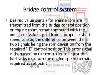
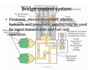
1) The basic closed-loop control of engine speed using a two or three-term controller that compares desired and measured RPM values and adjusts fuel to maintain set speed. Electronic, electro-pneumatic or hydraulic systems transmit signals and control fuel racks.
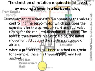
2) Lever controls in the bridge select engine direction and start/stop sequences, with safety interlocks. Speed is set on the bridge and transmitted to governors.
3) Bridge instrumentation includes RPM, direction indicators and starting air pressure. Alarms warn of machinery faults so the bridge is aware of issues.