- The document discusses the forces of drag and lift that act on a boomerang during flight and how its design dictates its motion. It aims to develop a physical understanding of these forces and apply mathematical models to analyze what causes a boomerang's angular precession and return.
- The dominant torque is due to the unbalanced lift forces acting on the rotating boomerang. This torque causes the boomerang's principal axis to change direction during flight, which results in its precession and return path.
- A mathematical model is derived and used with MATLAB to simulate the theoretical flight path of a boomerang based on its design parameters and motion characteristics. The model considers the boomerang's position,
BEST PPT FOR DOWNLOADING & SUBMISSION
INFORMATION IN POINTS
When the inertia forces are considered in the analysis of the mechanism, the analysis is known as dynamic force analysis.
Now applying D’Alembert principle one may reduce a dynamic system into an equivalent static system and use the techniques used in static force analysis to study the system.
Garcia and Bayo (1994), Wang and Wang (1998), Shi and Mc Phee (2000) were interested in the analytical and
experimental study of the dynamic response of these mechanisms
Unit 4- balancing of rotating masses, Dynamics of machines of VTU Syllabus prepared by Hareesha N Gowda, Asst. Prof, Dayananda Sagar College of Engg, Blore. Please write to hareeshang@gmail.com for suggestions and criticisms.
EE5317: Gyroscopes
Gyros are devices which rely on inertial measurements to measure changes in the orientation of an object. When gyros are combined with accelerometers, all the parameters necessary to determine the position and orientation of an object are available. A combined unit called an “Inertial Measurement Unit” is a common component of aircraft, missiles and other valuable objects whose trajectory needs to be determined by indirect means.
Static balance occurs when the center of gravity of an object is on the axis of rotation. This allows the object to remain stationary, with the axis horizontal, without the application of any braking force. Static balance does not tend to rotate due to the force of gravity.
Static Balance is when the weight of the wheel and tire assembly is distributed equally around the axis of the wheel rotation. If static Balance exists the wheel will not tend to rotate.
Dynamic balancing definition: “Dynamic balancing is a way of balancing machines by rotating parts quickly and measuring the imbalance using electronic equipment. The imbalance measured can then be corrected by adding or subtracting weight from the rotating parts until the vibration is reduced.”
Static force analysis, Unit-1 of Dynamics of machines of VTU Syllabus compiled by Hareesha N Gowda, Asst. Prof, Dayananda Sagar College of Engg, Blore. Please write to hareeshang@gmail.com for suggestions and criticisms.
The various forces acts on the reciprocating parts of an engine.
The resultant of all the forces acting on the body of the engine due to inertia forces only is known as unbalanced force or shaking force.
This presentation introduces the concept of "impact reduction factor" and a new method that are both developed by Dr. Niyazi Özgür Bezgin to estimate vertical impact forces on railways due to track stiffness variations.
Static Aeroelasticity Analysis of Spinning Rocket for Divergence Speed -- Zeu...Abhishek Jain
Above Research Paper can be downloaded from www.zeusnumerix.com
The research paper aims to develop a method to model the spin effects of rocket for Aeroelastic analysis. As the speed of the rocket increases, the structural integrity of the fins becomes more dependent on aeroelastic loads. Methods exist to analyze aeroelasticity of fins for non-spinning missiles. Most software use panel methods for calculation of load distribution. The current research replaces the panel methods to RANS CFD and introduces source terms in equations to model spin. The results of new formulation are validated w.r.t. published data on non-spinning projectile and then the method is used to simulate current projectile. Mode shapes up to 6th mode are delivered as result. Authors - Sanjay Kumar and Prof GR Shevare (Zeus Numerix), Subhash Mukane and PT Rojatkar (ARDE, DRDO)
International journal of engineering and mathematical modelling vol2 no2_2015_2IJEMM
The railway track is modeled as a continuous beam on elastic support. Train circulation is a random dynamic phenomenon and, according to the different frequencies of the loads it imposes, there exists the corresponding response of track superstructure. At the moment when an axle passes from the location of a sleeper, a random dynamic load is applied on the sleeper. The theoretical approach for the estimation of the dynamic loading of a sleeper demands the analysis of the total load acting on the sleeper to individual component loads-actions, which, in general, can be divided into:
• the static component of the load‚ and the relevant to it reaction/action per support point of the rail (sleeper)
• the dynamic component of the load, and the relevant to it reaction/action per support point of the rail (sleeper)
The dynamic component of the load of the track depends on the mechanical properties (stiffness, damping) of the system “vehicle-track”, and on the excitation caused by the vehicle’s motion on the track. The response of the track to the aforementioned excitation results in the increase of the static loads on the superstructure. The dynamic load is primarily caused by the motion of the vehicle’s Non-Suspended (Unsprung) Masses, which are excited by track geometry defects, and, to a smaller degree, by the effect of the Suspended (Sprung) Masses. In order to formulate the theoretical equations for the calculation of the dynamic component of the load, the statistical probability of exceeding the calculated load -in real conditions- should be considered, so that the corresponding equations refer to the standard deviation (variance) of the load.
In the present paper the dynamic component is investigated through the second order differential equation of motion of the Non Suspended Masses of the Vehicle and specifically the transient response of the reaction/ action on each support point (sleeper) of the rail. The case of a deformed or bent joint or welding is analyzed through the second order differential equation of motion and the solution is investigated.
UNIT-I
STATIC & DYNAMIC FORCE ANALYSIS Static equilibrium of two/three force members, Static
equilibrium of member with two forces and torque, Static force analysis of linkages, D'Alembert's
principle, Equivalent offset inertia force, Dynamic force analysis of four link mechanism and slider crank
mechanism, Dynamically equivalent system
TURNING MOMENT & FLYWHEEL Engine force analysis-Piston and crank effort, Turning moment
on crankshaft, Turning moment diagrams-single cylinder double acting steam engine, four stroke IC
engine and multi-cylinder steam engine, Fluctuation of energy, Flywheel and its design
UNIT-II
Governors Terminology Centrifugal governors- Watt goveror, Dead weight. govc ernors-Porter Proell
Spring controlled governor-Hartnel govemnor, Sensitivity, Stability, Hunting. Isochronism,
and Power of govemnor
Gyroscopic Motion Principles, Gyroscopic torque, Effect of gyroscopic couple on the stability of aero
planes, ships& automobiles
UNIT-III
BALANCING OF MACHINES Static and dynamic balancing, Balancing of several masses rotating in the
same plane and different planes, Balancing of primary and secondary forces in reciprocating engine, Partial
palancing of two-cylinder locomotives, Variation of tractive force, swaying couple, hammer blow,
Balancing of two cylinder in-line engines
MECHANICAL VIBRATIONS Introduction, Single degree free & damped vibrations of spring-mass
system, Logarithmic decrement, Tforsional vibration, Forced vibration of single degree system under
harmonic excitation, Critical speeds of shaft
UNIT-IV
Friction Introduction Friction in journal bearing-friction circle, Pivots and collar friction-Flat and conical
pivot bearing Flat collar bearing, Belt drives-types, material, power transmitted, ratio of driving tensions for
flat belt, centrifugal tension, initial tension, rope drive-types Laws of friction, Efficiency on inclined plane,
of
Screw friction, Screw jack, Efficiency, Friction in journal bearing-friction circle, Pivots and collar friction-
Flat and conical pivot bearing, Flat collar bearing
Clutches, Bakes & Dynamometers Single and multiple dise friction clutches, Cone clutch, Brakes-types
Single and double shoe brake, Simple and differential Band brake, Band and Block brake, Absorption and
transmission dynamometers, Prony brake and rope brake dynamometers
A Review of Shortcomings of Driving principle for Spherical Drive Systemspaperpublications3
Abstract: Spherical drive system is a relatively new field of research, and it holds a lot of potential due to a ball’s ability to be holonomic and rebound from collisions. In order to provide propulsion to such a completely closed sphere several methods have been put forward by different researchers. This article aims at putting together a definitive and complete list of the limitations of every propulsion system, so that future product designers and researchers may be able to decide on which propulsion system suits their purpose. This article will also help future researchers to identify and therefore find ways to overcome these limitations.
During the last decades, several studies on suspension bridges under wind actions have been developed in civil engineering and many techniques have been used to approach this structural problem both in time and frequency domain. In this paper, four types of time domain techniques to evaluate the response and the stability of a long span suspension bridge are implemented: nonaeroelastic, steady, quasi steady, modified quasi steady. These techniques are compared considering both nonturbulent and turbulent flow wind modelling. The results show consistent differences both in the amplitude of the response and in the value of critical wind velocity.
Dynamic force analysis – Inertia force and Inertia torque– D Alembert’s principle –Dynamic Analysis in reciprocating engines – Gas forces – Inertia effect of connecting rod– Bearing loads – Crank shaft torque
DYNAMIC RESPONSE OF SIMPLE SUPPORTED BEAM VIBRATED UNDER MOVING LOAD sadiq emad
In this thesis, an experimental and numerical study of dynamic deflection and dynamic bending stress of beam-type structure under moving load has been carried out. The moving load is constant in magnitude and travels at a uniform speed. The dynamic analysis of beam-type structure is done by taking three different concentrated loads (4, 6 and 8) kg , each one of them travels at three different uniform speeds (0.15, 0.2 and 0.25) m/s .
1. −1
−0.5
0
0.5
1
0
0.5
1
1.5
2
0
0.5
1
1.5
2
2.5
3
displacement (x)displacement (y)
Altitude
RELEASE POINT
Acknowledgments
Thanks to our professors for the interest and support, Jenifer
Mellott for assisting in boomerang construction.
PROJECT GOALS
- Develop a physical understanding between the forces of
drag and lift acting on the body in motion and how design
parameters dictate this motion.
- Understand and apply the motion of the boomerang to
mathematical models of motion and analyze what causes the
angular precession, and ultimate return of the body.
.
Figure 1. Symmetric 4-Blade Constructed Model
References
1. John Taylor, Classical Mechanics Textbook, Ch. 10
2. Ernie Esser, UCLA Powerpoint, Web Access,.bashaar.org.il/files/boom
THEORY
The dominant torque is due to the unbalanced force of lift
acting on the rotational body. This resulting non-conservative
force of lift is determined by both the forward and rotational
speeds of the boomerang arms, acting in the the direction of
angular momentum. The torque is in a direction opposite to
the forward (thrown) velocity and perpendicular to the
angular momentum vector along the axis of rotation. This
resulting magnitude and direction of torque is responsible for
the steady change in the direction of angular momentum and
overall precession of the principal axis during flight for the
returning boomerang. The torque causes only a change in the
direction of the angular momentum, not the magnitude,
because the is perpendicular in direction1.
Figure 2. The rotation of the body about the principal axis (e3)
causes a difference in the lift forces which is dependent on the
translational velocity. A resulting torque forces the principal axis
to change in direction during flight. The overall lift also acts
against gravity to keep the boomerang in the air.
CONCLUSION
The overall flight pattern of a boomerang is determined
by several key forces. The lift forces, torque, and resulting
precession all depend on the geometry of the body as well as
the initial conditions as determined by the thrower.
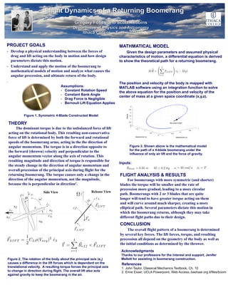
MATHMATICAL MODEL
Given the design parameters and assumed physical
characteristics of motion, a differential equation is derived
to show the theoretical path for a returning boomerang.
The position and velocity of the body is mapped with
MATLAB software using an integration function to solve
the above equation for the position and velocity of the
center of mass at a given space coordinate (x,y,z).
Inputs:
Figure 3. Shown above is the mathematical model
for the path of a 4-blade boomerang under the
influence of only air lift and the force of gravity.
FLIGHT ANALYSIS & RESULTS
For boomerangs with more symmetric (and shorter)
blades the torque will be smaller and the rate of
precession more gradual, leading to a more circular
path. Boomerangs with 2 or 3 blades that are quite
longer will tend to have greater torque acting on them
and will curve around much sharper, creating a more
elliptical path. Several parameters dictate this motion in
which the boomerang returns, although they may take
different flght paths due to their design.
Assumptions:
- Constant Rotation Speed
- Constant Bank Angle
- Drag Force is Negligible
- Bernouli Lift Equation Applies
Side View Release View