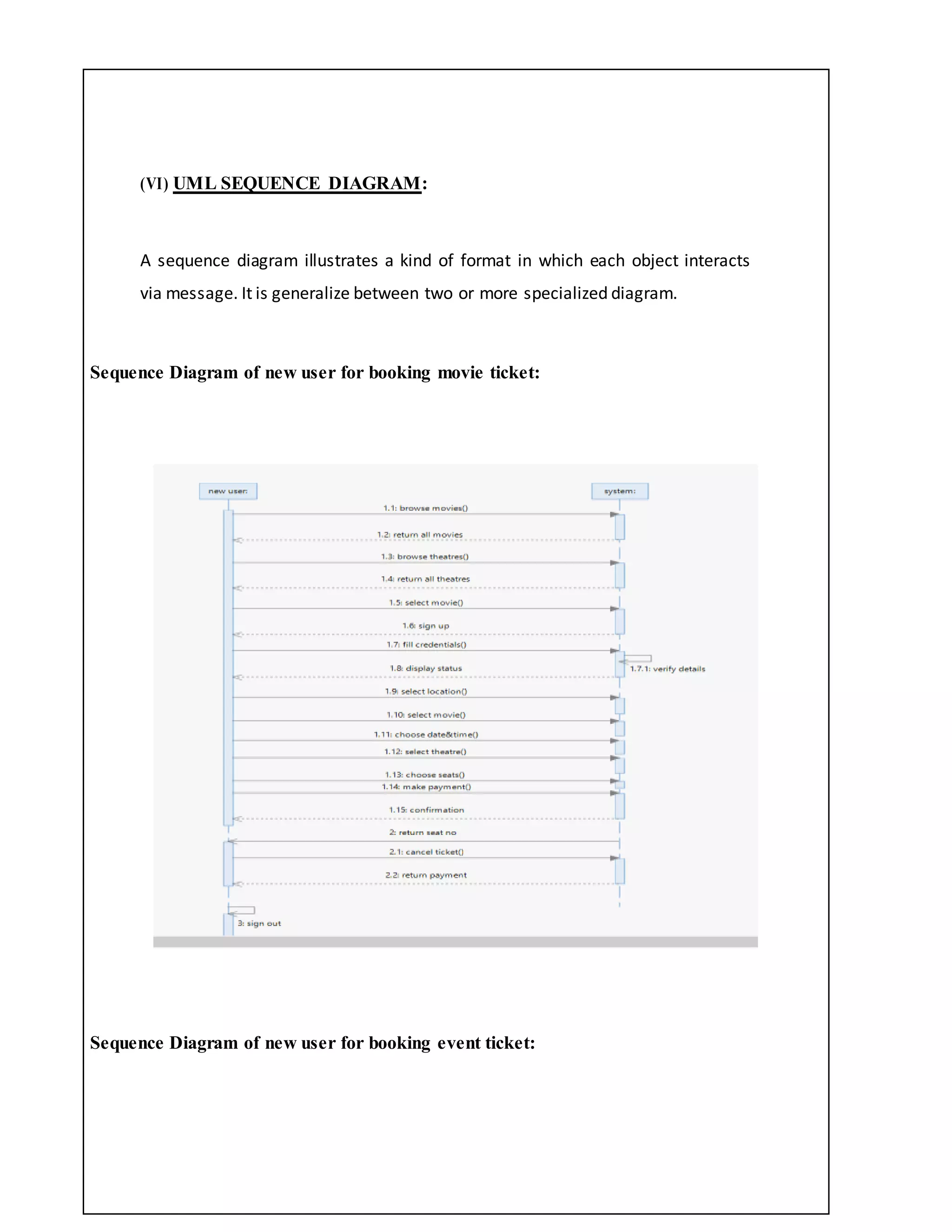
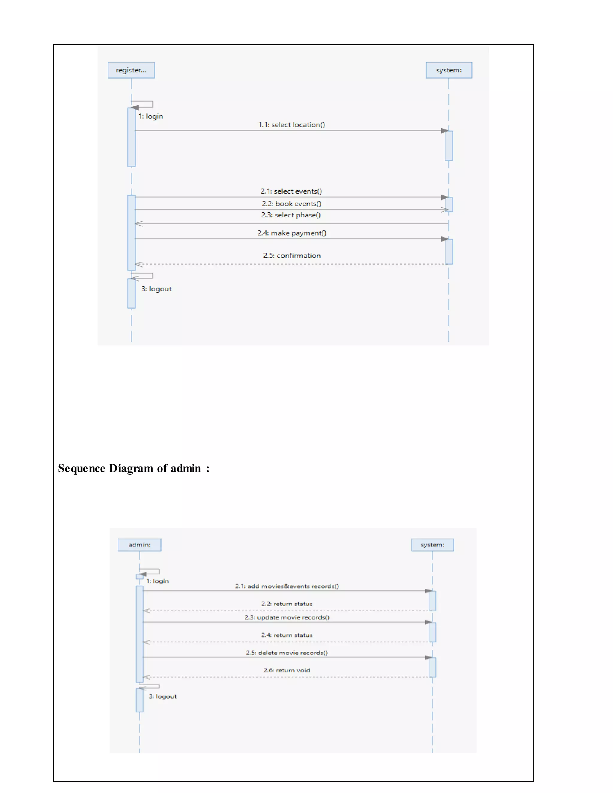
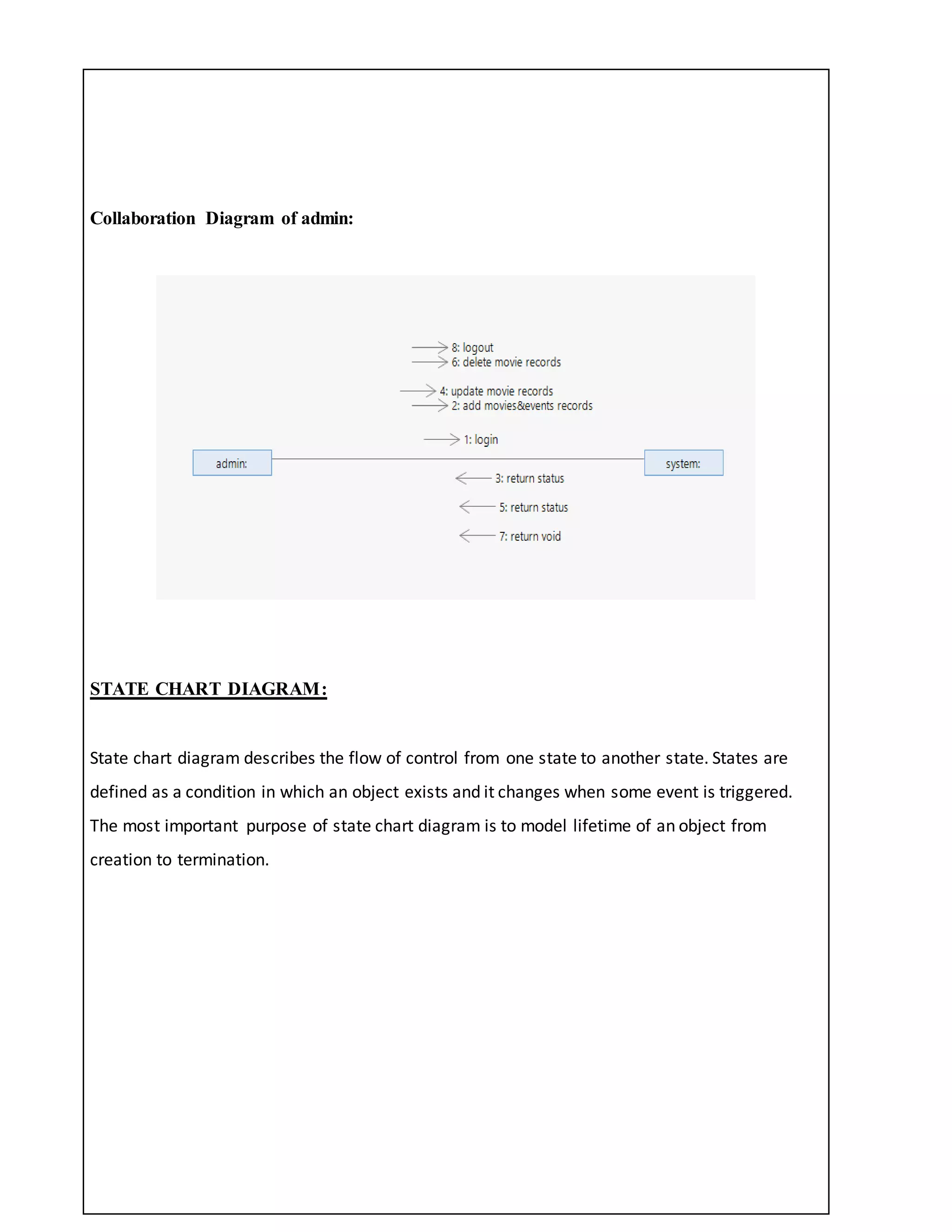
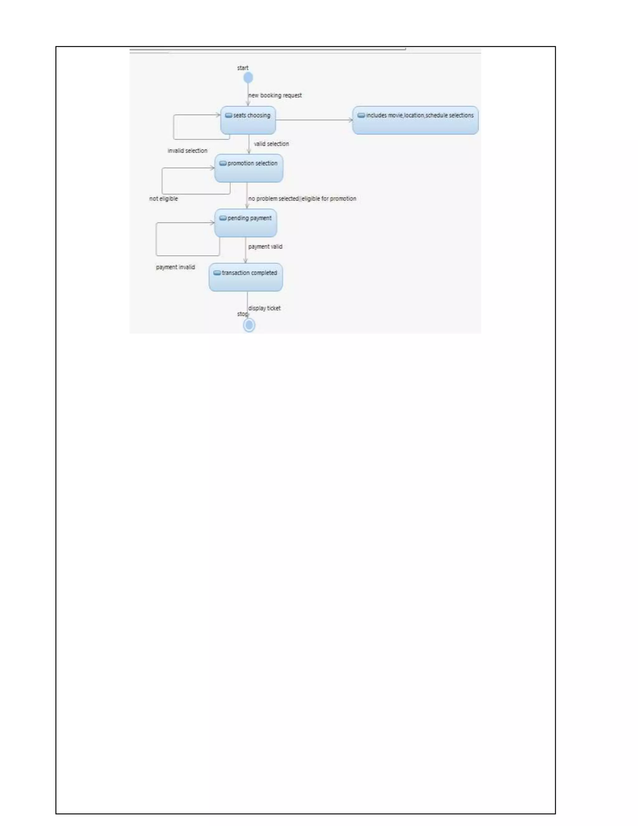
BOOK MY SHOW
AIM: To implement a software for Book My Show.
(I) PROBLEM STATEMENT:
Now a days people are busy with their works.There is no time to
know about the information happening around them.In this busy schedules,people are
interested to spend their weekends in joyful way.The weekend schedule of the persons differ
from one to one.Some people are interested to participate events but they don’t know what
events and activities are going in their near places.And some people are interested in movies.To
solve this problem and to give correct information about the events,activities and movies we
are introducing this application called BookMyShow.
(II) SOFTWARE REQUIREMENT SPECIFICATION:
1.0 INTRODUCTION
BookMyShow is an application which gives information about movies,events
which was through out the India.From this application the user can book the movie
tickets before.And we can book the tickets for the events which was taking place
through out the India.User can book the tickets according to their phase.It gives the
correct information about all the movies and activities that are taking place in India. We
can cancel the booking before 30 minutes.Through this application the planning
becomes easy and it reduces the time of the person because it shows all the information
about the movies and events in one platform.
1.1 PURPOSE
 To give the information about movies and events that are taking place in our
location.
 To give the correct and accurate information.
 To make the life easy and reduce the time for planning.
 More options for planning the weekend.
 To select the theatre for the movies and location for the events according to our
convenience,choice.
1.2 SCOPE
 BookMyShow application gives maximum information about the movies
and events.
 Users can book their movies and events from any place in anytime.
 There will be the more options for the users to select.
 It reduces the time for planning.
 To give correct and accurate information for the users.
1.3 DEFINITIONS, ACRONYMS AND THE ABBREVIATIONS
• User- One who uses the application
• Admin- One who develop the application
• System- Where all the changes stored.
2.0 OVERALL DESCRIPTION
2.1 PRODUCT PERSPECTIVE
The BookMyShow application makes the users planning easier by showing all
the movies and events near by them.By this application the time of he users will be
save.It gives various options for the users for their activity.This application gives the
accurate and exact results.
2.2 SOFTWARE INTERFACE
 Operating System: Windows 8.1/8/7/NT/2000/XP/Linux
 Languages:J2EE,JSP,HTML,JAVA SCRIPT,JQuery
 Development tools:ECLIPSE Luna
 Database:ORACLE 11g
 Framework:Spring 4.x,Hibernate 4
 Web server:Apache Tomcat
2.3HARDWARE INTERFACE
 Operating System:32/64 bit
 Processor:pentium4/Dual ccore/x-86 Processor
 RAM:2GB
 Hard Diisk:40GB
2.4SYSTEM FUNCTIONS
 In this application the user can login.
 .He can book the tickets for movies and events that are taking place in overall
India.
 User can add the offers which are available for him.
 User can order the .food and beverages at the time of booking ticket
 Comprehensive reports have been developed to track the status of the
documents at any given point of time.The user can cancel the booking in
before 30 minutes the money will be refunded.
 This application provides so many options for payment
2.5USER CHARACTERISTICS
• User- The user can book,cancel the tickets for the movies and events.The
payment was in various options.
• Admin - He has the certain activities such as add,delete,update the information
about the movies and activities
2.6CONSTRAINTS
• This application need internet to use.
• The refund money will be credited into user accounts after 3 to 4 working days.
2.7ASSUMPTIONS AND DEPENDENCIES
• To book the tickets for the movies and for the events the bank account
for the user is needed.
( III )USECASE DIAGRAM:
The BookMyShow use cases are:
1. Book movie
2. Cancel movie
3. Book events
4. Cancel events
5. Update information
6. Payment
ACTORS:
Actors are as follows:
1. User
2. Admin
3. System
ACTORS DOCUMENTATION:
1. User:
 Book movie
 Cancel movie
 Book event
 Cancel event
 Payment
2. Admin:
Update information
3. System:
Book movie
Cancel movie
Book events
Cancel events
Update information
Payment
USE-CASE NAME: book movie
The user book the ticket for the movie and the data was stored in the system.
USE-CASE NAME:cancel movie
The user can cancel the ticket of the movie,after booking the ticket only the
cancellation will take be take place.After the cancellation of the ticket the
updated information will be stored in the system.
USE-CASE NAME: book events
The user book the ticket for the event and the data was stored in the system.
USE-CASE NAME: cancel events
The user can cancel the ticketof the event,afterbookingthe ticketonlythe cancellationwill take
be take place.Afterthe cancellationof the ticketthe updatedinformationwillbe storedinthe
system
USE-CASE NAME: update information
The adminwill update the informationinthe applicationwhichwasusefultouserwheneverthe
newmoviesandeventsare there andthe updatedinformationwillstoredinthe system.
USE-CASE NAME: payment
The user can done the payment after booking the ticket for the movie or
event.The payment can be done in various options.
UML USE CASE DIAGRAM
Use case diagrams are usually referred to as behavior diagrams used to describe a set of actions
(use cases) that some system or systems (subject) should or can perform in collaboration with
one or more external users of the system (actors). Each use case should provide some
observable and valuable result to the actors or other stakeholders of the system.
(IV) ACTIVITY DIAGRAM:
Activity diagrams are graphical representations of workflows of stepwise activities and
actions with support for choice, iteration and concurrency. In the Unified Modeling
Language, activity diagrams can be used to describe the business and operational step-
by- step work flows of components in a system. An activity diagram shows the overall
flow of control. An activity is shown as an rounded box containing the name of the
operation.
This activity diagram describes the behaviour of the system.
Activity of New User for booking movie ticket:
Activity of new user for booking event ticket:
Activity Diagram of Registereduser for booking a movie ticket:
Activity Diagram of RegisteredUser for booking event ticket
Activity Diagram for Admin:
(V) UML CLASS DIAGRAM:
The UML class diagram is to illustrate class interfaces and their actions. They are used
for static object modeling, we have already introduced and used their UML diagram
while domain modeling.
(VI) UML SEQUENCE DIAGRAM:
A sequence diagram illustrates a kind of format in which each object interacts
via message. It is generalize between two or more specialized diagram.
Sequence Diagram of new user for booking movie ticket:
Sequence Diagram of new user for booking event ticket:
Sequence Diagram of registered user for booking movie ticket:
Sequence Diagram of registered user for booking event ticket:
Sequence Diagram of admin :
COMMUNICATION DIAGRAM:
Communication diagram illustrate that object interact on a graph or network format in
which object can be placed where on the diagram. In collaboration diagram the object
can be placed in anywhere on the diagram. The collaboration comes from sequence
diagram.
Collaboration Diagram of new user for booking a movie ticket:
Collaboration Diagram of new user for booking a event ticket:
Collaboration Diagram of registered user for booking movie ticket:
Collaboration Diagram of registered user for booking event ticket:
Collaboration Diagram of admin:
STATE CHART DIAGRAM:
State chart diagram describes the flow of control from one state to another state. States are
defined as a condition in which an object exists and it changes when some event is triggered.
The most important purpose of state chart diagram is to model lifetime of an object from
creation to termination.
COMPONENT DIAGRAM:
Component diagrams can also be described as a static implementation
view of a system. Static implementation represents the organization of the components at a
particular moment.A single component diagram cannot represent the entire system but a
collection of diagrams is used to represent the whole.
DEPLOYMENT DIAGRAM:
Deployment diagrams are used to visualize the topology of the physical
components of a system where the software components are deployed.
.
DIVYA SURE
17MIS7054

BookMyShow

  • 1.
    BOOK MY SHOW AIM:To implement a software for Book My Show. (I) PROBLEM STATEMENT: Now a days people are busy with their works.There is no time to know about the information happening around them.In this busy schedules,people are interested to spend their weekends in joyful way.The weekend schedule of the persons differ from one to one.Some people are interested to participate events but they don’t know what events and activities are going in their near places.And some people are interested in movies.To solve this problem and to give correct information about the events,activities and movies we are introducing this application called BookMyShow. (II) SOFTWARE REQUIREMENT SPECIFICATION: 1.0 INTRODUCTION BookMyShow is an application which gives information about movies,events which was through out the India.From this application the user can book the movie tickets before.And we can book the tickets for the events which was taking place through out the India.User can book the tickets according to their phase.It gives the correct information about all the movies and activities that are taking place in India. We can cancel the booking before 30 minutes.Through this application the planning becomes easy and it reduces the time of the person because it shows all the information about the movies and events in one platform.
  • 2.
    1.1 PURPOSE  Togive the information about movies and events that are taking place in our location.  To give the correct and accurate information.  To make the life easy and reduce the time for planning.  More options for planning the weekend.  To select the theatre for the movies and location for the events according to our convenience,choice. 1.2 SCOPE  BookMyShow application gives maximum information about the movies and events.  Users can book their movies and events from any place in anytime.  There will be the more options for the users to select.  It reduces the time for planning.  To give correct and accurate information for the users. 1.3 DEFINITIONS, ACRONYMS AND THE ABBREVIATIONS • User- One who uses the application • Admin- One who develop the application
  • 3.
    • System- Whereall the changes stored. 2.0 OVERALL DESCRIPTION 2.1 PRODUCT PERSPECTIVE The BookMyShow application makes the users planning easier by showing all the movies and events near by them.By this application the time of he users will be save.It gives various options for the users for their activity.This application gives the accurate and exact results. 2.2 SOFTWARE INTERFACE  Operating System: Windows 8.1/8/7/NT/2000/XP/Linux  Languages:J2EE,JSP,HTML,JAVA SCRIPT,JQuery  Development tools:ECLIPSE Luna  Database:ORACLE 11g  Framework:Spring 4.x,Hibernate 4  Web server:Apache Tomcat 2.3HARDWARE INTERFACE  Operating System:32/64 bit  Processor:pentium4/Dual ccore/x-86 Processor  RAM:2GB  Hard Diisk:40GB
  • 4.
    2.4SYSTEM FUNCTIONS  Inthis application the user can login.  .He can book the tickets for movies and events that are taking place in overall India.  User can add the offers which are available for him.  User can order the .food and beverages at the time of booking ticket  Comprehensive reports have been developed to track the status of the documents at any given point of time.The user can cancel the booking in before 30 minutes the money will be refunded.  This application provides so many options for payment 2.5USER CHARACTERISTICS • User- The user can book,cancel the tickets for the movies and events.The payment was in various options. • Admin - He has the certain activities such as add,delete,update the information about the movies and activities 2.6CONSTRAINTS • This application need internet to use. • The refund money will be credited into user accounts after 3 to 4 working days. 2.7ASSUMPTIONS AND DEPENDENCIES • To book the tickets for the movies and for the events the bank account for the user is needed.
  • 5.
    ( III )USECASEDIAGRAM: The BookMyShow use cases are: 1. Book movie 2. Cancel movie 3. Book events 4. Cancel events 5. Update information 6. Payment ACTORS: Actors are as follows: 1. User 2. Admin 3. System ACTORS DOCUMENTATION: 1. User:  Book movie  Cancel movie  Book event  Cancel event  Payment
  • 6.
    2. Admin: Update information 3.System: Book movie Cancel movie Book events Cancel events Update information Payment USE-CASE NAME: book movie The user book the ticket for the movie and the data was stored in the system. USE-CASE NAME:cancel movie The user can cancel the ticket of the movie,after booking the ticket only the cancellation will take be take place.After the cancellation of the ticket the updated information will be stored in the system. USE-CASE NAME: book events The user book the ticket for the event and the data was stored in the system. USE-CASE NAME: cancel events The user can cancel the ticketof the event,afterbookingthe ticketonlythe cancellationwill take be take place.Afterthe cancellationof the ticketthe updatedinformationwillbe storedinthe system USE-CASE NAME: update information The adminwill update the informationinthe applicationwhichwasusefultouserwheneverthe newmoviesandeventsare there andthe updatedinformationwillstoredinthe system.
  • 7.
    USE-CASE NAME: payment Theuser can done the payment after booking the ticket for the movie or event.The payment can be done in various options. UML USE CASE DIAGRAM Use case diagrams are usually referred to as behavior diagrams used to describe a set of actions (use cases) that some system or systems (subject) should or can perform in collaboration with one or more external users of the system (actors). Each use case should provide some observable and valuable result to the actors or other stakeholders of the system.
  • 8.
    (IV) ACTIVITY DIAGRAM: Activitydiagrams are graphical representations of workflows of stepwise activities and actions with support for choice, iteration and concurrency. In the Unified Modeling Language, activity diagrams can be used to describe the business and operational step- by- step work flows of components in a system. An activity diagram shows the overall flow of control. An activity is shown as an rounded box containing the name of the operation. This activity diagram describes the behaviour of the system.
  • 9.
    Activity of NewUser for booking movie ticket:
  • 10.
    Activity of newuser for booking event ticket:
  • 11.
    Activity Diagram ofRegistereduser for booking a movie ticket: Activity Diagram of RegisteredUser for booking event ticket
  • 12.
  • 13.
    (V) UML CLASSDIAGRAM: The UML class diagram is to illustrate class interfaces and their actions. They are used for static object modeling, we have already introduced and used their UML diagram while domain modeling.
  • 14.
    (VI) UML SEQUENCEDIAGRAM: A sequence diagram illustrates a kind of format in which each object interacts via message. It is generalize between two or more specialized diagram. Sequence Diagram of new user for booking movie ticket: Sequence Diagram of new user for booking event ticket:
  • 16.
    Sequence Diagram ofregistered user for booking movie ticket: Sequence Diagram of registered user for booking event ticket:
  • 17.
  • 18.
    COMMUNICATION DIAGRAM: Communication diagramillustrate that object interact on a graph or network format in which object can be placed where on the diagram. In collaboration diagram the object can be placed in anywhere on the diagram. The collaboration comes from sequence diagram. Collaboration Diagram of new user for booking a movie ticket: Collaboration Diagram of new user for booking a event ticket:
  • 19.
    Collaboration Diagram ofregistered user for booking movie ticket: Collaboration Diagram of registered user for booking event ticket:
  • 20.
    Collaboration Diagram ofadmin: STATE CHART DIAGRAM: State chart diagram describes the flow of control from one state to another state. States are defined as a condition in which an object exists and it changes when some event is triggered. The most important purpose of state chart diagram is to model lifetime of an object from creation to termination.
  • 22.
    COMPONENT DIAGRAM: Component diagramscan also be described as a static implementation view of a system. Static implementation represents the organization of the components at a particular moment.A single component diagram cannot represent the entire system but a collection of diagrams is used to represent the whole. DEPLOYMENT DIAGRAM: Deployment diagrams are used to visualize the topology of the physical components of a system where the software components are deployed.
  • 23.