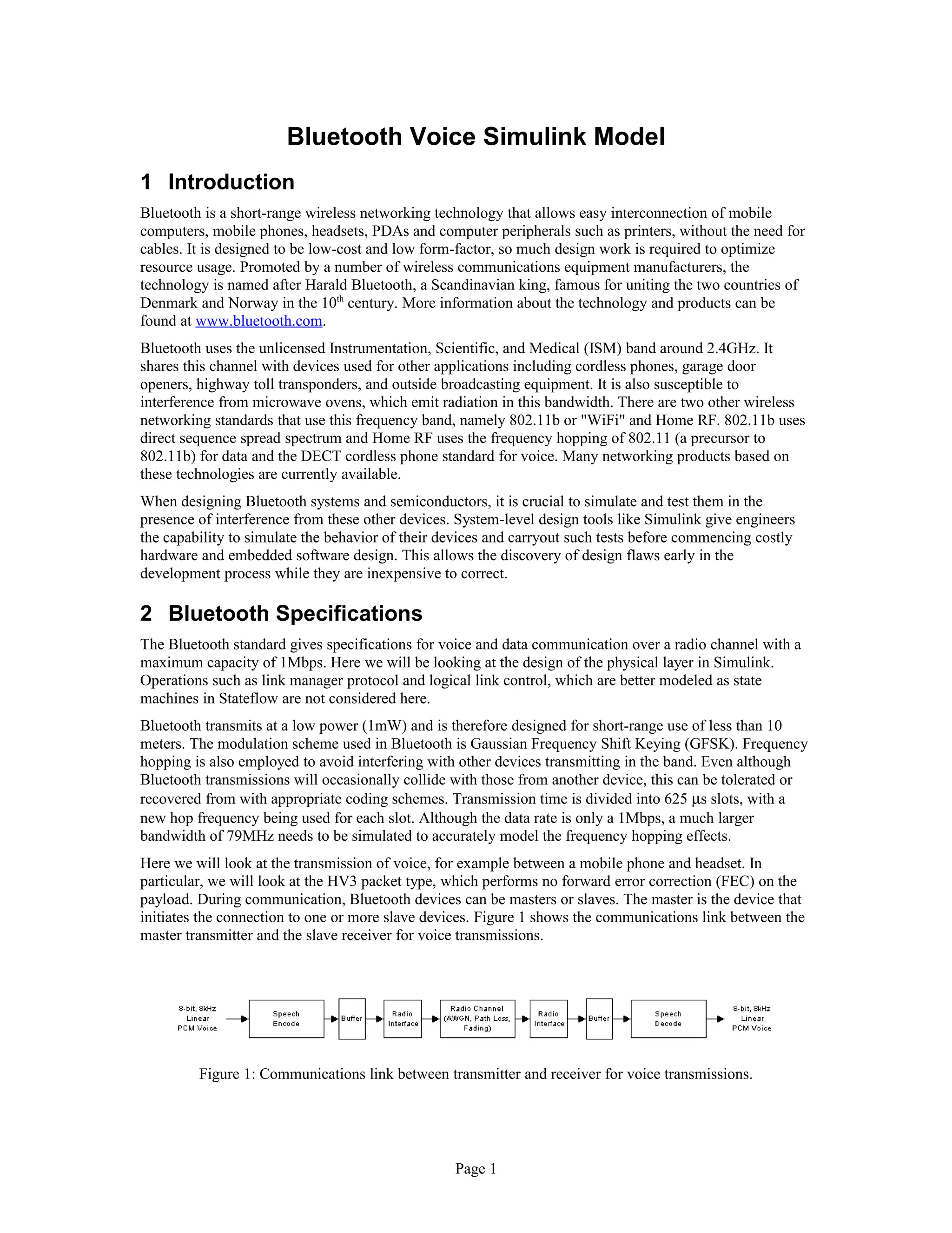
Bluetooth Voice Simulink Model
1 Introduction
Bluetooth is a short-range wireless networking technology that allows easy interconnection of mobile
computers, mobile phones, headsets, PDAs and computer peripherals such as printers, without the need for
cables. It is designed to be low-cost and low form-factor, so much design work is required to optimize
resource usage. Promoted by a number of wireless communications equipment manufacturers, the
technology is named after Harald Bluetooth, a Scandinavian king, famous for uniting the two countries of
Denmark and Norway in the 10th
century. More information about the technology and products can be
found at www.bluetooth.com.
Bluetooth uses the unlicensed Instrumentation, Scientific, and Medical (ISM) band around 2.4GHz. It
shares this channel with devices used for other applications including cordless phones, garage door
openers, highway toll transponders, and outside broadcasting equipment. It is also susceptible to
interference from microwave ovens, which emit radiation in this bandwidth. There are two other wireless
networking standards that use this frequency band, namely 802.11b or "WiFi" and Home RF. 802.11b uses
direct sequence spread spectrum and Home RF uses the frequency hopping of 802.11 (a precursor to
802.11b) for data and the DECT cordless phone standard for voice. Many networking products based on
these technologies are currently available.
When designing Bluetooth systems and semiconductors, it is crucial to simulate and test them in the
presence of interference from these other devices. System-level design tools like Simulink give engineers
the capability to simulate the behavior of their devices and carryout such tests before commencing costly
hardware and embedded software design. This allows the discovery of design flaws early in the
development process while they are inexpensive to correct.
2 Bluetooth Specifications
The Bluetooth standard gives specifications for voice and data communication over a radio channel with a
maximum capacity of 1Mbps. Here we will be looking at the design of the physical layer in Simulink.
Operations such as link manager protocol and logical link control, which are better modeled as state
machines in Stateflow are not considered here.
Bluetooth transmits at a low power (1mW) and is therefore designed for short-range use of less than 10
meters. The modulation scheme used in Bluetooth is Gaussian Frequency Shift Keying (GFSK). Frequency
hopping is also employed to avoid interfering with other devices transmitting in the band. Even although
Bluetooth transmissions will occasionally collide with those from another device, this can be tolerated or
recovered from with appropriate coding schemes. Transmission time is divided into 625 µs slots, with a
new hop frequency being used for each slot. Although the data rate is only a 1Mbps, a much larger
bandwidth of 79MHz needs to be simulated to accurately model the frequency hopping effects.
Here we will look at the transmission of voice, for example between a mobile phone and headset. In
particular, we will look at the HV3 packet type, which performs no forward error correction (FEC) on the
payload. During communication, Bluetooth devices can be masters or slaves. The master is the device that
initiates the connection to one or more slave devices. Figure 1 shows the communications link between the
master transmitter and the slave receiver for voice transmissions.
Figure 1: Communications link between transmitter and receiver for voice transmissions.
Page 1
Figure 2 shows a more detailed block diagram of the transmitter only, including speech coding, whitening,
Header Error Check (HEC), FEC, framing, modulation, frequency hopping, and RF subsystem.
Figure 2: Transmitter specification.
In Bluetooth, voice transmission is known as a Synchronous Connection Oriented (SCO) type of
communication and transmits only every sixth slot. This time period, equal to 3.75ms, is denoted TSCO. The
return, slave to master path, transmits on the next slot as shown in Figure 3. Up to three simultaneous voice
calls can be supported this way.
Figure 3: Timing diagram of three simultaneous voice calls.
3 Simulink Model
Such a communication system can be constructed from the blocks found in the Simulink, DSP Blockset,
and Communications Blockset libraries. Custom blocks can be constructed from other primitive blocks or
specified with C Code if needed. One way to construct such a link in Simulink is to start with the channel
and work out, adding modulation, FEC, etc. testing at each stage. It is also useful to design component pairs
separately, for example the speech encoder and decoder can be built and tested in their own model and then
inserted into the link once they have been tested.
Figure 4 shows the top-level of the complete Bluetooth voice Simulink model. It comprises a master
transmitter, radio channel, 802.11b interferer, slave receiver plus error meters, and instrumentation. Here
only the top level is shown. Simulink's hierarchical modeling features allow large complex designs to be
managed and modularized into subsystems. Opening up these subsystems reveals further levels of detail.
Page 2
Figure 4: Simulink model of Bluetooth voice transmission.
The model makes extensive use of frame based processing in Simulink, which can propagate large frames
of samples at each execution step allowing for much faster simulation of digital systems. For example, a 10
tap FIR filter can process a 1MHz signal in real-time on an 800MHz Pentium. In this particular model, a
top sample rate of 100MHz is used. Frame based processing also allows for easy modeling of block-based
operations like forward error correction and cyclic redundancy checks (CRC), which operate on finite
length frames of data. The frame widths in this model were displayed next to the signals by selecting the
‘Signal Dimensions’ option from the format menu. The many different sample rates in the model, which
including two speech rates, the Bluetooth slot rate and the 1/6 slot rate, can be visualized by selecting the
'Sample-time colors' option from the format menu, as shown Figure 5. Yellow denotes a block that has
multiple sample rates such as in a Downsample block.
Page 3
Figure 5: The ‘Sample-time Colors’ option highlights the various model sample rates
4 Master Transmitter
The transmitter subsystem shown in Figure 6, replicates the specification of Figure 2, in performing, voice
input, speech coding, buffering, framing, HEC, FEC, modulation, and frequency hopping. The only
operation omitted is whitening which can be added by using the Scrambling block form the
Communications Blockset.
Figure 6: Simulink transmitter subsystem.
Page 4
CVSD Speech Coding
Two speech coders are specified in the standard: Continuous Variable Slope Decoding (CVSD) and 64kbps
log PCM (G.711). CVSD is the method implemented in this model. A Wavread block first brings in a 8kHz
signal from a wave file. It then interpolates the signal up to 64kHz ready for speech coding. The CVSD
speech coder encodes each sample with a single bit using a differential coding scheme, which transmits a
1bit if the speech sample increases from the previous value and a 0 bit if it decreases. Such schemes are
very robust to bit errors. It a bit is corrupted in transmission then the decoded speech at the receiver will
only be in error by a small fraction of the total amplitude range. The CVSD block is constructed from
Simulink primitive arithmetic blocks following the Bluetooth specification and placed in a masked
subsystem presenting the user with all key parameters as shown in Figure 7. The output of the coder is a
64Kbps stream, which is buffered into frames of 240 bits, equivalent to 3.75ms of speech.
Figure 7: CVSD block parameters.
HEC, FEC and Framing
The raw 240-bit speech payload has to be augmented with additional control information as shown in
Figure 8. Figure 6 shows the concatenation of the 72-bit access code, the 54-bit header, and 240-bit payload
into a 366-bit frame.
ACCESS Code
72 bits
HEADER
54 bits
PAYLOAD
240 bits of speech
366 bits
AM
Addr
3
Type
4
Flow
1
ARQ
1
SEQ
1
HEC
8
Figure 8: Access code, header, and payload framing specification.
The 54-bit header is formed from the simple FEC repeating of the 18-bit header information (header infor)
and header error check (HEC) bits. The HEC is an 8-bit CRC calculated from the 10-bit header info. The
header info contains a number of pieces of important data including slave address, packet type, and status
bits. In the model, these values are taken from variables in the workspace, which were defined by the
initialization function 'bluetooth_init.m'. The HEC operation is specified in C Code using the S-Function
Builder block. The S-Function Builder block provides a GUI dialog containing pre-defined input and
output C variables that can be processed with custom code as shown in Figure 9.
Page 5
1/3 FEC
Figure 9: S-Function Builder GUI for HEC block.
Modulation and Frequency Hopping
The 366 data bits are transmitted at 1 Mbps and modulated using GFSK. GFSK effectively transmits +150
kHz signal relative to the carrier for a 1bit, and a -150kHz signal for a 0 bit. This functionality is
implemented inside the ‘GFSK modulation and frequency hopping’ subsystem shown in Figure 10, using
the Continuous Phase Modulation (CPM) block set to appropriate values such as modulation index. By
specifying 100 samples per symbol this modulator block outputs a narrow bandwidth complex baseband
signal centered around 0 Hz with a sample rate of .01 µs (or +/- 50Mhz frequency range). These samples
are simulated in frames of 62500 samples resulting in a slot rate of 625 µs.
To avoid interference with other ISM devices, Bluetooth transmits on a different carrier frequency each
slot. This is achieved in the model by multiplying the baseband signal with one of 79 possible complex
carriers with frequencies in the range +⁄- 39MHz as shown in Figure 10 performing an ideal mixing
operation. The carrier signal is generated in the Simulink model by a baseband MFSK block set to 79
symbols and a separation of 1MHz. If a hop frequency value 0 is input, a -39MHz complex sinusoid is
generated. If a 1 is entered, a -38 MHz complex sinusoid is generated and so on. In the model, the hop
sequences are generated by a simple random number generator, not using the actual method specified in the
standard.
The transmitter is turned off after 366 bits using a Gain block to multiply the frame with a mask of 36600
ones and 26500 zeros.
Page 6
Figure 10: GFSK modulation and frequency hopping.
As voice transmission only uses every 6th slot, the modulator, which is set to execute at the slot rate, is
placed in an enabled subsystem set to turn on once every 6th
sample instant (or at the SCO rate). The actual
slot used can be controlled by changing the location of the ‘1’ in the vector contained inside the Signal
From Workspace block feeding the enable port.
Finally, the transmitted signal's power is set it to 0dBm (1mW) for a power class 1 device. Here, effects due
to the RF stages, including further mixing to 2.4GHz and filtering, are not included in the model.
Transmitter Simulation
When the simulation runs with the instrumentation block turned on, the timing diagram in Figure 11 shows
when the Bluetooth transmitter is operational. The plot in Figure 12, displays the power spectrum of each
channel slot, showing the current Bluetooth hop frequency. These two characteristics are viewed together
on the spectrogram scope in Figure 13 to easily track hop frequency versus time.
Figure 11: Bluetooth signal timing.
Figure 12: Channel spectrum.
Figure 13: Channel spectrogram.
Page 7
5 Channel and Interferer Modeling
Channel effects that need to be modeled include noise, fading, path loss and interference. All of these
effects are modeled here except for fading, which can be added using a Rayleigh or Rician fading block
from the Communications Blockset. Looking once again at the complete communication link diagram of
Figure 4, path loss is modeled with a dB attenuation block set to -20dB, the result of a 1m separation
between transmitter and receiver. White noise is added using an AWGN block with an appropriate symbol
to noise energy (Es⁄No) value selected. This block is masked in a subsystem to allow enabling or disabling
of the noise. Due to the 100MHz bandwidth, the channel takes a large percentage of the simulation time.
Individual block execution time can be accurately measured with the Simulink Profiler, which is part of the
Simulink Performance Tools product.
The 802.11b's 11MHz direct sequence chip rate results in a bandwidth of approximately 22MHz. The
Simulink block generating this signal is a masked subsystem allowing the user to specify parameters
including mean packet rate, packet length, power, and frequency location in the ISM band. The 22MHz
bandwidth is generated by appropriately filtering a white noise source resulting in the spectrum in Figure
14.
Figure 14: 802.11b spectrum.
Being a packet-based system, 802.11b’s transmission can be characterized as bursts of activity at a Poisson
rate; bursts that are not aligned to the Bluetooth slot boundaries. Looking under the mask of the 802.11b
transmitter block as shown in Figure 15, we see that the burstiness of the signal is created by enabling the
noise generating subsystem with a stream of pulses arriving at a Poisson rate and having a width equal to
the packet length. The block generating the pulse train is an M Code S-Function block, which uses some
advanced features of Simulink to control when it is executed. Figure 15 shows the M code in the S-
Function that tells Simulink when to execute it next, calculated from a random Poisson variable.
Figure 15: Poisson process block enabling a 22 MHz noise source.
Page 8
Figure 16:Variable hit S-Function.
When the 802.11b transmitter is turned on, the timing diagram in Figure 17 shows the overlap of the
Bluetooth and 802.11b transmissions. The spectrogram in Figure 18 clearly shows the interaction of
transmissions from the two devices including which packets are colliding.
Figure 17: Bluetooth and 802.11b timing diagram.
Figure 18: Channel spectrogram.
6 Slave Receiver
It is the task of the receiver to recover the speech from the transmitted radio signal. The receiver is usually
more complicated than the transmitter due to the requirement to synchronize and detect errors. In principle,
it comprises all the same operations as in the transmitter but in reverse order. Looking inside the Slave
Receiver subsystem reveals the blocks as shown in Figure 19. This particular model does not include any
synchronization i.e. it is assumed to be fully synchronized. Such operations can added by using a phase-
locked loop (PLL). Frame synchronization can be modeled with a Stateflow finite state machine.
Page 9
Figure 19: Simulink receiver subsystem.
After de-hopping with the same hop sequence as in the transmitter and demodulation by a subsystem
enabled once every 6 slots, the 366 bits are generated. The access code, header, and payload are then
extracted. The header is de-repeated to expose the 8-bit HEC and 10-bit header info for checking. Frame
failure, caused by excessive noise or interference, is determined if the HEC fails to match the header info or
less than 57 bits are correct in the access code. If the frame fails, this is noted by a zero-valued Frame OK
signal, which is used in FER calculations, as well as to exclude bad frames from the residual BER
calculation. The extracted payload is then ignored and replaced with a 1,0,1,0... sequence, which will cause
the CVSD decoder to hold its current level.
7 Testing
Testing a model for one set of parameters can be achieved by just running the Simulink simulation and
viewing the generated results. Testing a model through a range of parameter values is best done with a
MATLAB script consisting of a 'for loop' that sets parameters in the model, runs the simulation multiple
times and notes the results. These results need to be returned to the MATLAB workspace by 'To
Workspace' blocks in the model.
The following tests analyze various effects in the Bluetooth system and channel. The tables show model
parameter values together with simulation results.
1) Simple Simulation
Parameters and results:
Tes
t
Input Speech 802.11b AWGN Hop Frequency BER FER Output Speech
i) Input.wav Off Eb⁄No=5 Random 4.3 e-4 0 Output_1i.wav
ii) Input.wav Off Eb⁄No=0 Random 2.7 e-2 9.7e-3 Output_1ii.wav
iii) Input.wav Off Eb⁄No=-2 Random 6.4 e-2 0.18 Output_1iii.wav
2) BER versus Eb/No
Page 10
A common test to perform on any communication is to measure how the BER varies with the ratio of bit
energy (Eb) or symbol energy (Es) to noise energy (No), denoted Eb/No or Es/No . Here Eb= Es as there is one
symbol for every bit. The BER meter is contained in the error meter subsystem, which can be opened for
viewing during the simulation. The final values of the meters are saved to workspace variables for later
collection and analysis. The M code used to perform the BER test in Figure 20.
Parameters and results:
802.11b AWGN Hop Frequency BER
Off Eb/No =1:1:15 Random Figure 21
Figure 20: M Code to run simulation multiple times and generate BER plot.
Figure 21: BER versus Eb/No
3) BER versus hop frequency with 802.11b
Another interesting test is to look at the BER as a function of hop frequency when the 802.11b transmitter
is permanently on. It would be expected that performance of the Bluetooth system would degrade as it
entered the 802 transmitter’s bandwidth.
Parameters and results:
802.11b AWGN Hop Frequency BER
Page 11
Packet Rate = 999 (Fixed On) Off 0:78 Figure 22
Figure 22: BER versus hop frequency with 802 permanently on.
4) 802.11b effect on voice quality
The effect of 802.11b interference on voice quality is shown here with the 802.11b transmitter set to two
different packets rates.
Parameters and results:
Test Input Speech 802.11b AWGN Hop Frequency BER FER Output Wave
i) Input.wav Packet Rate = 200 Off Random 1.6e-2 3.8e-2 Output_4i.wav
ii) Input.wav Packet Rate = 500 Off Random 4.6e-2 0.12 Output_4ii.wav
iii) Input.wav Packet Rate = 999
(Always On)
Off Random 9.2e-2 0.21 Output_4iii.wav
Any number of simulations can be run in this way to test or optimize the performance of the system as a
function of system parameters and environmental characteristics.
8 Conclusion
Testing system and semiconductor designs early in the design process in this way can substantially increase
the chance of locating and correcting design flaws while they are inexpensive to correct. This reduces the
risk of design flaws surfacing late when they are expensive to correct and can seriously delay product
delivery. Having a clear architecture specification is also invaluable in aiding communication and
minimizing misunderstandings among project team members.
The model described in this article can be downloaded from the MATLAB Central website at
www.mathworks.com⁄matlabcentral⁄bluetooth file
Page 12
The author would like to acknowledge the help of P.G. Madhavan of Bluetooth Applications Group at
Agere Systems, who developed the model in collaboration with the author and gave extensive advice on
Bluetooth.
Page 13

Bluetooth voice

  • 1.
    Bluetooth Voice SimulinkModel 1 Introduction Bluetooth is a short-range wireless networking technology that allows easy interconnection of mobile computers, mobile phones, headsets, PDAs and computer peripherals such as printers, without the need for cables. It is designed to be low-cost and low form-factor, so much design work is required to optimize resource usage. Promoted by a number of wireless communications equipment manufacturers, the technology is named after Harald Bluetooth, a Scandinavian king, famous for uniting the two countries of Denmark and Norway in the 10th century. More information about the technology and products can be found at www.bluetooth.com. Bluetooth uses the unlicensed Instrumentation, Scientific, and Medical (ISM) band around 2.4GHz. It shares this channel with devices used for other applications including cordless phones, garage door openers, highway toll transponders, and outside broadcasting equipment. It is also susceptible to interference from microwave ovens, which emit radiation in this bandwidth. There are two other wireless networking standards that use this frequency band, namely 802.11b or "WiFi" and Home RF. 802.11b uses direct sequence spread spectrum and Home RF uses the frequency hopping of 802.11 (a precursor to 802.11b) for data and the DECT cordless phone standard for voice. Many networking products based on these technologies are currently available. When designing Bluetooth systems and semiconductors, it is crucial to simulate and test them in the presence of interference from these other devices. System-level design tools like Simulink give engineers the capability to simulate the behavior of their devices and carryout such tests before commencing costly hardware and embedded software design. This allows the discovery of design flaws early in the development process while they are inexpensive to correct. 2 Bluetooth Specifications The Bluetooth standard gives specifications for voice and data communication over a radio channel with a maximum capacity of 1Mbps. Here we will be looking at the design of the physical layer in Simulink. Operations such as link manager protocol and logical link control, which are better modeled as state machines in Stateflow are not considered here. Bluetooth transmits at a low power (1mW) and is therefore designed for short-range use of less than 10 meters. The modulation scheme used in Bluetooth is Gaussian Frequency Shift Keying (GFSK). Frequency hopping is also employed to avoid interfering with other devices transmitting in the band. Even although Bluetooth transmissions will occasionally collide with those from another device, this can be tolerated or recovered from with appropriate coding schemes. Transmission time is divided into 625 µs slots, with a new hop frequency being used for each slot. Although the data rate is only a 1Mbps, a much larger bandwidth of 79MHz needs to be simulated to accurately model the frequency hopping effects. Here we will look at the transmission of voice, for example between a mobile phone and headset. In particular, we will look at the HV3 packet type, which performs no forward error correction (FEC) on the payload. During communication, Bluetooth devices can be masters or slaves. The master is the device that initiates the connection to one or more slave devices. Figure 1 shows the communications link between the master transmitter and the slave receiver for voice transmissions. Figure 1: Communications link between transmitter and receiver for voice transmissions. Page 1
  • 2.
    Figure 2 showsa more detailed block diagram of the transmitter only, including speech coding, whitening, Header Error Check (HEC), FEC, framing, modulation, frequency hopping, and RF subsystem. Figure 2: Transmitter specification. In Bluetooth, voice transmission is known as a Synchronous Connection Oriented (SCO) type of communication and transmits only every sixth slot. This time period, equal to 3.75ms, is denoted TSCO. The return, slave to master path, transmits on the next slot as shown in Figure 3. Up to three simultaneous voice calls can be supported this way. Figure 3: Timing diagram of three simultaneous voice calls. 3 Simulink Model Such a communication system can be constructed from the blocks found in the Simulink, DSP Blockset, and Communications Blockset libraries. Custom blocks can be constructed from other primitive blocks or specified with C Code if needed. One way to construct such a link in Simulink is to start with the channel and work out, adding modulation, FEC, etc. testing at each stage. It is also useful to design component pairs separately, for example the speech encoder and decoder can be built and tested in their own model and then inserted into the link once they have been tested. Figure 4 shows the top-level of the complete Bluetooth voice Simulink model. It comprises a master transmitter, radio channel, 802.11b interferer, slave receiver plus error meters, and instrumentation. Here only the top level is shown. Simulink's hierarchical modeling features allow large complex designs to be managed and modularized into subsystems. Opening up these subsystems reveals further levels of detail. Page 2
  • 3.
    Figure 4: Simulinkmodel of Bluetooth voice transmission. The model makes extensive use of frame based processing in Simulink, which can propagate large frames of samples at each execution step allowing for much faster simulation of digital systems. For example, a 10 tap FIR filter can process a 1MHz signal in real-time on an 800MHz Pentium. In this particular model, a top sample rate of 100MHz is used. Frame based processing also allows for easy modeling of block-based operations like forward error correction and cyclic redundancy checks (CRC), which operate on finite length frames of data. The frame widths in this model were displayed next to the signals by selecting the ‘Signal Dimensions’ option from the format menu. The many different sample rates in the model, which including two speech rates, the Bluetooth slot rate and the 1/6 slot rate, can be visualized by selecting the 'Sample-time colors' option from the format menu, as shown Figure 5. Yellow denotes a block that has multiple sample rates such as in a Downsample block. Page 3
  • 4.
    Figure 5: The‘Sample-time Colors’ option highlights the various model sample rates 4 Master Transmitter The transmitter subsystem shown in Figure 6, replicates the specification of Figure 2, in performing, voice input, speech coding, buffering, framing, HEC, FEC, modulation, and frequency hopping. The only operation omitted is whitening which can be added by using the Scrambling block form the Communications Blockset. Figure 6: Simulink transmitter subsystem. Page 4
  • 5.
    CVSD Speech Coding Twospeech coders are specified in the standard: Continuous Variable Slope Decoding (CVSD) and 64kbps log PCM (G.711). CVSD is the method implemented in this model. A Wavread block first brings in a 8kHz signal from a wave file. It then interpolates the signal up to 64kHz ready for speech coding. The CVSD speech coder encodes each sample with a single bit using a differential coding scheme, which transmits a 1bit if the speech sample increases from the previous value and a 0 bit if it decreases. Such schemes are very robust to bit errors. It a bit is corrupted in transmission then the decoded speech at the receiver will only be in error by a small fraction of the total amplitude range. The CVSD block is constructed from Simulink primitive arithmetic blocks following the Bluetooth specification and placed in a masked subsystem presenting the user with all key parameters as shown in Figure 7. The output of the coder is a 64Kbps stream, which is buffered into frames of 240 bits, equivalent to 3.75ms of speech. Figure 7: CVSD block parameters. HEC, FEC and Framing The raw 240-bit speech payload has to be augmented with additional control information as shown in Figure 8. Figure 6 shows the concatenation of the 72-bit access code, the 54-bit header, and 240-bit payload into a 366-bit frame. ACCESS Code 72 bits HEADER 54 bits PAYLOAD 240 bits of speech 366 bits AM Addr 3 Type 4 Flow 1 ARQ 1 SEQ 1 HEC 8 Figure 8: Access code, header, and payload framing specification. The 54-bit header is formed from the simple FEC repeating of the 18-bit header information (header infor) and header error check (HEC) bits. The HEC is an 8-bit CRC calculated from the 10-bit header info. The header info contains a number of pieces of important data including slave address, packet type, and status bits. In the model, these values are taken from variables in the workspace, which were defined by the initialization function 'bluetooth_init.m'. The HEC operation is specified in C Code using the S-Function Builder block. The S-Function Builder block provides a GUI dialog containing pre-defined input and output C variables that can be processed with custom code as shown in Figure 9. Page 5 1/3 FEC
  • 6.
    Figure 9: S-FunctionBuilder GUI for HEC block. Modulation and Frequency Hopping The 366 data bits are transmitted at 1 Mbps and modulated using GFSK. GFSK effectively transmits +150 kHz signal relative to the carrier for a 1bit, and a -150kHz signal for a 0 bit. This functionality is implemented inside the ‘GFSK modulation and frequency hopping’ subsystem shown in Figure 10, using the Continuous Phase Modulation (CPM) block set to appropriate values such as modulation index. By specifying 100 samples per symbol this modulator block outputs a narrow bandwidth complex baseband signal centered around 0 Hz with a sample rate of .01 µs (or +/- 50Mhz frequency range). These samples are simulated in frames of 62500 samples resulting in a slot rate of 625 µs. To avoid interference with other ISM devices, Bluetooth transmits on a different carrier frequency each slot. This is achieved in the model by multiplying the baseband signal with one of 79 possible complex carriers with frequencies in the range +⁄- 39MHz as shown in Figure 10 performing an ideal mixing operation. The carrier signal is generated in the Simulink model by a baseband MFSK block set to 79 symbols and a separation of 1MHz. If a hop frequency value 0 is input, a -39MHz complex sinusoid is generated. If a 1 is entered, a -38 MHz complex sinusoid is generated and so on. In the model, the hop sequences are generated by a simple random number generator, not using the actual method specified in the standard. The transmitter is turned off after 366 bits using a Gain block to multiply the frame with a mask of 36600 ones and 26500 zeros. Page 6
  • 7.
    Figure 10: GFSKmodulation and frequency hopping. As voice transmission only uses every 6th slot, the modulator, which is set to execute at the slot rate, is placed in an enabled subsystem set to turn on once every 6th sample instant (or at the SCO rate). The actual slot used can be controlled by changing the location of the ‘1’ in the vector contained inside the Signal From Workspace block feeding the enable port. Finally, the transmitted signal's power is set it to 0dBm (1mW) for a power class 1 device. Here, effects due to the RF stages, including further mixing to 2.4GHz and filtering, are not included in the model. Transmitter Simulation When the simulation runs with the instrumentation block turned on, the timing diagram in Figure 11 shows when the Bluetooth transmitter is operational. The plot in Figure 12, displays the power spectrum of each channel slot, showing the current Bluetooth hop frequency. These two characteristics are viewed together on the spectrogram scope in Figure 13 to easily track hop frequency versus time. Figure 11: Bluetooth signal timing. Figure 12: Channel spectrum. Figure 13: Channel spectrogram. Page 7
  • 8.
    5 Channel andInterferer Modeling Channel effects that need to be modeled include noise, fading, path loss and interference. All of these effects are modeled here except for fading, which can be added using a Rayleigh or Rician fading block from the Communications Blockset. Looking once again at the complete communication link diagram of Figure 4, path loss is modeled with a dB attenuation block set to -20dB, the result of a 1m separation between transmitter and receiver. White noise is added using an AWGN block with an appropriate symbol to noise energy (Es⁄No) value selected. This block is masked in a subsystem to allow enabling or disabling of the noise. Due to the 100MHz bandwidth, the channel takes a large percentage of the simulation time. Individual block execution time can be accurately measured with the Simulink Profiler, which is part of the Simulink Performance Tools product. The 802.11b's 11MHz direct sequence chip rate results in a bandwidth of approximately 22MHz. The Simulink block generating this signal is a masked subsystem allowing the user to specify parameters including mean packet rate, packet length, power, and frequency location in the ISM band. The 22MHz bandwidth is generated by appropriately filtering a white noise source resulting in the spectrum in Figure 14. Figure 14: 802.11b spectrum. Being a packet-based system, 802.11b’s transmission can be characterized as bursts of activity at a Poisson rate; bursts that are not aligned to the Bluetooth slot boundaries. Looking under the mask of the 802.11b transmitter block as shown in Figure 15, we see that the burstiness of the signal is created by enabling the noise generating subsystem with a stream of pulses arriving at a Poisson rate and having a width equal to the packet length. The block generating the pulse train is an M Code S-Function block, which uses some advanced features of Simulink to control when it is executed. Figure 15 shows the M code in the S- Function that tells Simulink when to execute it next, calculated from a random Poisson variable. Figure 15: Poisson process block enabling a 22 MHz noise source. Page 8
  • 9.
    Figure 16:Variable hitS-Function. When the 802.11b transmitter is turned on, the timing diagram in Figure 17 shows the overlap of the Bluetooth and 802.11b transmissions. The spectrogram in Figure 18 clearly shows the interaction of transmissions from the two devices including which packets are colliding. Figure 17: Bluetooth and 802.11b timing diagram. Figure 18: Channel spectrogram. 6 Slave Receiver It is the task of the receiver to recover the speech from the transmitted radio signal. The receiver is usually more complicated than the transmitter due to the requirement to synchronize and detect errors. In principle, it comprises all the same operations as in the transmitter but in reverse order. Looking inside the Slave Receiver subsystem reveals the blocks as shown in Figure 19. This particular model does not include any synchronization i.e. it is assumed to be fully synchronized. Such operations can added by using a phase- locked loop (PLL). Frame synchronization can be modeled with a Stateflow finite state machine. Page 9
  • 10.
    Figure 19: Simulinkreceiver subsystem. After de-hopping with the same hop sequence as in the transmitter and demodulation by a subsystem enabled once every 6 slots, the 366 bits are generated. The access code, header, and payload are then extracted. The header is de-repeated to expose the 8-bit HEC and 10-bit header info for checking. Frame failure, caused by excessive noise or interference, is determined if the HEC fails to match the header info or less than 57 bits are correct in the access code. If the frame fails, this is noted by a zero-valued Frame OK signal, which is used in FER calculations, as well as to exclude bad frames from the residual BER calculation. The extracted payload is then ignored and replaced with a 1,0,1,0... sequence, which will cause the CVSD decoder to hold its current level. 7 Testing Testing a model for one set of parameters can be achieved by just running the Simulink simulation and viewing the generated results. Testing a model through a range of parameter values is best done with a MATLAB script consisting of a 'for loop' that sets parameters in the model, runs the simulation multiple times and notes the results. These results need to be returned to the MATLAB workspace by 'To Workspace' blocks in the model. The following tests analyze various effects in the Bluetooth system and channel. The tables show model parameter values together with simulation results. 1) Simple Simulation Parameters and results: Tes t Input Speech 802.11b AWGN Hop Frequency BER FER Output Speech i) Input.wav Off Eb⁄No=5 Random 4.3 e-4 0 Output_1i.wav ii) Input.wav Off Eb⁄No=0 Random 2.7 e-2 9.7e-3 Output_1ii.wav iii) Input.wav Off Eb⁄No=-2 Random 6.4 e-2 0.18 Output_1iii.wav 2) BER versus Eb/No Page 10
  • 11.
    A common testto perform on any communication is to measure how the BER varies with the ratio of bit energy (Eb) or symbol energy (Es) to noise energy (No), denoted Eb/No or Es/No . Here Eb= Es as there is one symbol for every bit. The BER meter is contained in the error meter subsystem, which can be opened for viewing during the simulation. The final values of the meters are saved to workspace variables for later collection and analysis. The M code used to perform the BER test in Figure 20. Parameters and results: 802.11b AWGN Hop Frequency BER Off Eb/No =1:1:15 Random Figure 21 Figure 20: M Code to run simulation multiple times and generate BER plot. Figure 21: BER versus Eb/No 3) BER versus hop frequency with 802.11b Another interesting test is to look at the BER as a function of hop frequency when the 802.11b transmitter is permanently on. It would be expected that performance of the Bluetooth system would degrade as it entered the 802 transmitter’s bandwidth. Parameters and results: 802.11b AWGN Hop Frequency BER Page 11
  • 12.
    Packet Rate =999 (Fixed On) Off 0:78 Figure 22 Figure 22: BER versus hop frequency with 802 permanently on. 4) 802.11b effect on voice quality The effect of 802.11b interference on voice quality is shown here with the 802.11b transmitter set to two different packets rates. Parameters and results: Test Input Speech 802.11b AWGN Hop Frequency BER FER Output Wave i) Input.wav Packet Rate = 200 Off Random 1.6e-2 3.8e-2 Output_4i.wav ii) Input.wav Packet Rate = 500 Off Random 4.6e-2 0.12 Output_4ii.wav iii) Input.wav Packet Rate = 999 (Always On) Off Random 9.2e-2 0.21 Output_4iii.wav Any number of simulations can be run in this way to test or optimize the performance of the system as a function of system parameters and environmental characteristics. 8 Conclusion Testing system and semiconductor designs early in the design process in this way can substantially increase the chance of locating and correcting design flaws while they are inexpensive to correct. This reduces the risk of design flaws surfacing late when they are expensive to correct and can seriously delay product delivery. Having a clear architecture specification is also invaluable in aiding communication and minimizing misunderstandings among project team members. The model described in this article can be downloaded from the MATLAB Central website at www.mathworks.com⁄matlabcentral⁄bluetooth file Page 12
  • 13.
    The author wouldlike to acknowledge the help of P.G. Madhavan of Bluetooth Applications Group at Agere Systems, who developed the model in collaboration with the author and gave extensive advice on Bluetooth. Page 13