The document compares the fatigue properties and fatigue crack growth rates of various implantable metals, including Ti-15Zr-4Nb-4Ta alloy, commercially pure titanium grade 4, titanium alloy Ti-6Al-4V, stainless steels, and cobalt-chromium alloys. Fatigue tests were conducted on smooth and notched specimens to determine fatigue strength. Fatigue crack growth tests were also performed to measure crack growth rates. The fatigue properties of Ti-15Zr-4Nb-4Ta alloy were found to be influenced by specimen configuration, manufacturing process, heat treatment, and stress intensity factor. The fatigue strengths of materials were generally improved by cold working, heat treatment like aging or solution treatment, and stress
A contribution to new material standards for Ductile Ironsand Austempered Duc...Franco Zanardi
Some results of materials characterization activities, dedicated to classical and notch mechanics fatigue andelastoplastic properties, have already been published for some Ferritic–Pearlitic Ductile Iron, including the patented heat treated Isother med (IDI) and Austempered DuctileIron (ADI) grades. Others have not yet been published. The possible use of all of these results in new standards is discussed in this paper.
Effect of deep cryogenic treatment on surface integrity and dimensional stabi...eSAT Journals
Abstract Deep cryogenic treatment is an add-on process to conventional heat treatment in which material is treated at cryogenic temperature. The mechanical properties of the tool steel are significantly improved by Deep Cryogenic treatment. Surface integrity and dimensional stability is having greater impact on the functional performance of the tool during service conditions. The objective of this work is to investigate the effect of deep cryogenic treatment on the surface integrity and dimensional stability of the D2 tool steel. The metallographic samples and Navy C Rings of D2 Tool steel were treated at cryogenic temperature of -1930C after hardening and tempering. Results have shown improvement in surface roughness. The improved surface roughness is attributed to the release of tensile residual stresses and more precipitation and uniform distribution of fine secondary carbides. DCT have higher shape distortion than CHT. The distortions in DCT can be attributed to the section sensitivity of D2 Tool steel. Keywords: Surface integrity, distortion, precipitation of secondary carbides, section sensitivity
Effects of cryogenic treatment on tool steel aisi d6eSAT Journals
Abstract
In present technological modern age. All the manufacturers adopt that process which governs to higher productivity that has been achieved by the various treatment of tool steel. These conventional processes improve no of characteristics to fulfill desired purpose. But all these process does not provided fully satisfaction from conventional heat treatment process. Thus a new process is being additionally employed for improving mechanical properties called cryogenic treatment process or sub-zero treatment of tool steels. During this process tool steel is proceed below Atmospheric tem. That is in minus about (-1960 C or 3100 F). Due to cooling, steel alter their mechanical properties like wear resistance, Hardness, toughness, fatigue life micro-structure alteration etc. Cryo-treatment not only improve its mechanical properties but also improve thermal properties, electrical properties & easier machining etc. in this paper cryogenic treatment of tool steel AISI-D6 is perform and study is made for wear-resistance, Hardness, toughness, with respect to untreated test specimen of same, we have got improved wear-resistance capacity improve hardness as well as toughness.
Keywords – AISI-D6 tool steel, cryogenic process, wear resistance, Hardness, Toughness.
CMEME2015 Conference: "Understanding hydrogen behaviour in steels" Daniel Gaude-Fugarolas
Invited Plenary Presentation at CMEME2015 Conference in Biskra, Algeria, 8-9Dec2015.
ABSTRACT:
Small amounts of hydrogen can sometimes cause embrittlement of high strength alloys. Because of their technological and economic relevance, intense research is underway worldwide to improve our understanding of such phenomena.
A physical model has been used to study hydrogen behaviour during manufacturing of metallic alloys. In particular, the present model contemplates diffusion in its most comprehensive description, i.e., atom diffusion being driven by the gradient in chemical activation, instead of simply occurring down a composition gradient. The model incorporates as well the influence of thermal history, microstructure, matrix solubility, multiple trapping distributions, and interaction with the atmosphere.
Using this model is possible to describe and predict the behaviour of hydrogen in metals during real industrial processes. For instance, it explains the effect on hydrogen redistribution of parameters like treatment conditions, component size and microstructure, phase transformation temperature, grain size, carbide distribution, deformation level, etc.
Furthermore, a set of criteria have been developed to anticipate defect formation and embrittlement risk, based on hydrogen supersaturation.
Last but not least, a method has been developed during this work, which enables to reduce hydrogen content from the metal via the use of imposed temperature gradients. This method has recently obtained several patents.
This is a presentation on hydrogen induced cracking ,sulfide stress cracking and test procedure for HIC resistant steel
DENZIL D’SOUZA
denzil22@gmail.com
Heat Transfer, Hardenability and Steel Phase Transformations during Gas Quenc...YuanLu49
https://digitalcommons.wpi.edu/etd-dissertations/399/
"Quenching is the rapid cooling process from an elevated temperature. Compared to water and oil quench medium, high pressure and velocity gas is preferred to quench medium and high hardenability steel, with the potential to reduce distortion, stress and cracks. Currently, no standard test exists to characterize the gas quench steel hardenability and measure the performance of industrial gas quench furnaces. In this thesis, the fundamental difference between the liquid and gas quenching, heat transfer coefficient, was emphasized. It has been proven that gas quenching with constant HTC cannot generate the similar cooling curves compared to liquid quenching. Limitations on current gas quench steel hardenability tests were reviewed. Critical HTC, a concept like critical diameter, was successfully proved to describe the gas quench hardenability of steel. An attempt to use critical HTC test bar and measure the HTC distribution of gas quench furnace was made. Gas quenching, usually with slow cooling rate, may reduce hardness and Charpy impact toughness, compared to water and oil quenching. Lattice parameter and c/a ratio of as-quenched martensite in steel was measured using high resolution X-ray diffraction and Rietveld refinement. For AISI 4140, Charpy impact toughness decreases when the cooling rate decreases after quenching and tempering. Austenite percentage and carbon content in austenite is proposed as the dominated mechanism."
ASME section 2C Specifications for Welding Rods, Electrodes, and Filler Metals
ð
19
Þ
LIST OF SECTIONS
SECTIONS
I Rules for Construction of Power BoilersII Materials
•
Part A
—
Ferrous Material Specifications
•
Part B
—
Nonferrous Material Specifications
•
Part C
—
Specifications for Welding Rods, Electrodes, and Filler Metals
•
Part D
—
Properties (Customary)
•
Part D
—
Properties (Metric)III Rules for Construction of Nuclear Facility Components
•
Subsection NCA
—
General Requirements for Division 1 and Division 2
•
Appendices
•
Division 1
–
Subsection NB
—
Class 1 Components
–
Subsection NC
—
Class 2 Components
–
Subsection ND
—
Class 3 Components
–
Subsection NE
—
Class MC Components
–
Subsection NF
—
Supports
–
Subsection NG
—
Core Support Structures
•
Division 2
—
Code for Concrete Containments
•
Division 3
—
Containment Systems for Transportation and Storage of Spent Nuclear Fuel and High-LevelRadioactive Material
•
Division 5
—
High Temperature Reactors IV Rules for Construction of Heating BoilersV Nondestructive ExaminationVI Recommended Rules for the Care and Operation of Heating BoilersVII Recommended Guidelines for the Care of Power BoilersVIII Rules for Construction of Pressure Vessels
•
Division 1
•
Division 2
—
Alternative Rules
•
Division 3
—
Alternative Rules for Construction of High Pressure VesselsIX Welding, Brazing, and Fusing QualificationsX Fiber-Reinforced Plastic Pressure Vessels XI Rules for Inservice Inspection of Nuclear Power Plant Components
•
Division 1
—
Rules for Inspection and Testing of Components of Light-Water-Cooled Plants
•
Division 2
—
Requirements for Reliability and Integrity Management (RIM) Programs for Nuclear Power Plants XII Rules for Construction and Continued Service of Transport Tanks
Cryogenic treatment is a secondary process to traditional heat treatment used for improving the hardness and wear resistance of tool steels. Though the potential use of cryogenic treatment on AISI D2 tool steel under laboratory conditions has been well established by the researchers, it is essential to do the analysis to ensure its sustainable use for industrial application. Therefore, impact of cryogenic treatment on AISI D2 steel blanking punch was evaluated in terms of increase in production rate and its life. The cryogenically treated D2 tool steel punches were used and subjected to manufacture the control levers using blanking operations. The improved wear resistance of cryogenically treated punch resulted in increase in production and punch life more than 200%. Punch life was studied and correlated to increase in production & wear behavior of blanking punch. The AISI D2 steel samples were prepared and subjected to laboratory tests comprising of metallographic observations and hardness. It was found that laboratory tests were not enough to predict improvements in mechanical properties. The mechanism responsible for augmented wear resistance by cryogenic treatment was the conversion of retained austenite to martensite and precipitation of new secondary carbides.
The International Journal of Engineering and Science (The IJES)theijes
The International Journal of Engineering & Science is aimed at providing a platform for researchers, engineers, scientists, or educators to publish their original research results, to exchange new ideas, to disseminate information in innovative designs, engineering experiences and technological skills. It is also the Journal's objective to promote engineering and technology education. All papers submitted to the Journal will be blind peer-reviewed. Only original articles will be published.
Ahmed ibrahim razooqi...corrosion conduct of austenitic stainless steel 316 l...ahmed Ibrahim
Corrosion conduct of Austenitic stainless steel 316L subjected
to surface treatment.
Abstract. The influence of low temperature liquid nitriding as a surface heat treatment analogy
with laser peening treatment at the various of throbs on pitting corrosion of the “AISI 316L
Austenitic stainless steel” is investigated in this paper. According to typical ASTM (G71-31) a
number of corrosion examination samples are equipped with the measurements of (15 * 15 * 3)
mm which distributed into the many groups. Three sets were exposed to liquid nit riding
process at temperatures of (500, 400, 300) Co for one hour. The specimens (without coating)
were exposed to a number of the throbs (1,2,3) by laser peening. Microstructure varia tions,
compression residual stress, hardness, were inspected in this work. The corrosion and its
variables (potential cell, current density) were also evaluated using the potential stat
examination and applying the Tafel method using saltwater solution (3.5% NaCl). Tafle
equation was used to compute the corrosion degree. The results revealed that the liquid
nitriding participated to raise the corrosion rate at (500) Co, compared to the original metal
because of chromium nitride and also leaser peening participated to the increase in the
corrosion rate due to plastic deformation which led to the heterogeneity in the microstructure
but liquid nitriding at temperature (400) oC gave the best result where it was closer to the parent
metal’s, also laser peening at one throb showed the lower corrosion rate.
This paper presents a study that investigates the corrosion behavior of annealed 2205 duplex stainless steel in sulphuric acid environment. Duplex 2205 stainless steel black bar in ASTM A276 was obtained and annealed in solite furnace for 45 minutes. A control sample which was not heat treated was also prepared. The annealed and the control samples which were metallographically prepared were then analyzed for corrosion behavior in sulphuric acid using potentiodynamic test/analysis. The potentiodynamic polarization plot generated showed that the annealed samples exhibit less corrosion resistance than the untreated samples, indicating that annealing heat treatment reduces the corrosion resistance of 2205 duplex stainless steel in sulphuric acid.
Document describes, the Cryogenic definition, applications, various Melting Points and Boiling Points of cryogenic liquids and other liquids. selection of materials for cryogenic service, Timeline for Cryogenic Technology.
A Review on Mechanical and Wear Properties of Heat Treated SteelIJSRD
This Review Paper describes effects of heat treatment on various material by varying process parameters and by using different types of heat treatment process. The heat treatment includes heating & cooling operations or the sequence of two or more such operations applied to any material in order to modify metallurgical structure and alter its physical, mechanical and chemical properties. This Review paper shows progress and research in the field of heat treatment process. Different types of heat treatment processes such as annealing, normalising, nitriding, hardening, tempering carburising used & available in recent time. This paper deals with important progress work on heat treatment and its process parameters.
The Effect of Cryogenic Treatment on the Hardness, Friction and Wear Resista...IJMER
Investigations carried out in the recent few decades reveal the advantages of cryogenic
treatment as one of the promising techniques to enhance wear resistance in certain tool steels. Thus the
cryogenic treatment has significant influence on the tribological performance of tool steels. It is a one
time permanent treatment process affecting the entire section of the part, unlike coatings. Enhancing the
wear resistance and service life of the steel tools subjected to rubbing condition is of important concern.
Literature provides information about the investigations performed on some high-speed steels which
reveal remarkable improvement in wear resistance from 92% to 817%. Furthermore, the studies
conducted on conventional D3 tool steel reveals the betterment of certain tribo-mechanical properties
such as hardness and wear resistance. In the present investigation the effect of cryogenic treatment on
austenitic ductile iron type D3 tool steel is studied by sliding the test specimen against the same mating
material. The study reveals increase in hardness, reduction in friction coefficient and enhancement in
wear resistance
MECHANICAL PROPERTY ASSESSMENT OF AUSTEMPERED AND CONVENTIONALLY HARDENED AIS...IAEME Publication
The chemical composition and mechanical properties of steel decide its applicability for manufacturing various components in different areas of engineering interests. Heat treatment processes are commonly used to enhance the required properties of steel with or without change in chemical composition. The present work aims to perform conventional hardening and Austempering treatment with experimental investigation of the effect of austempering and conventional hardening (quenching) on AISI 4340 steel. Different tests like tensile, torsion, hardness, impact and microstructure analysis are carried out in as bought and heat treated conditions
EFFECT OF THERMAL EXPOSURE ON THE MECHANICAL AND WEAR PROPERTIES OF AEROSPACE...Journal For Research
Aluminum alloys are becoming increasingly important available data were utilized to prepare maps that are intended to serve to design Al Alloys with desired combination especially in the automotive and aerospace industries aluminum alloys AA6061 T6 is subjected to several combinations of solution treatments to correlate their mechanical tensile properties to hardness and conductivity measurement Additional the AA6061 T6 alloys were thermally exposed to several temperature to simulate heat damage effects the thermal exposure was correlated to the tensile properties and hardness and conductivity measurement however these materials tend to have poor wear resistance during working conditions study was to evaluate the wear behavior of Al alloys with various parameter by using pin-on-disk machine the wear rate was decreased then after database were created to consolidate the information about microstructure mechanical properties and corrosion behavior for Al Alloys.
Engineering Research Publication
Best International Journals, High Impact Journals,
International Journal of Engineering & Technical Research
ISSN : 2321-0869 (O) 2454-4698 (P)
www.erpublication.org
Influence of Heat Treatment on Mechanical Properties of Aisi1040 SteelIOSR Journals
This investigation is concerned to evaluate the influence of heat treatment on mechanical behavior of AISI1040 steel; it is one of the grades of medium carbon steel of American standard containing 0.40% carbon in its composition. Specimen of quenched/hardened AISI1040 steel was tempered at temperature (650,450&250℃) for 60, 90&120 minutes to modify desired properties. The mechanical behavior, particularly, ultimate tensile strength, yield strength and elongation were investigated using universal testing machine; while the hardness measurement was done on Rockwell hardness testing machine of heat treated specimens. Result shows that the ultimate tensile strength and the yield strength decrease while the elongation increases with an increase in tempering temperature and tempering time of different tempered specimen. The hardness of quenched/hardened specimen decreases with an increase in tempering temperature and tempering time. Furthermore, increasing temperature and lowering time produces approximately same result as decreasing temperature and increasing time.
Effects of Continuous Cooling On Impact and Micro Structural Properties of Lo...IJMER
Some mechanical properties and microstructural analysis were conducted on shielded
metal arc weldments of low carbon steels in some simulated environments. Specimens were prepared
and subjected to welding and continuous cooling at the same time at various positions. Results obtained
for impact strength using Charpy impact testing machine showed that impact strength of water cooled
samples were higher compared to salty water cooled samples. This is due to the increased formation of
martensitic structure and finer pearlite grains. The microstructure of the samples was studied using
photographic visual metallurgical microscope. For low cooling rate as in the air cooled sample, the
austenite was observed to transform into ferrite and pearlite. Ferrite is a body-centred cubic crystal
structure of iron alloys. For higher cooling rates of water and salt water cooled samples, low
temperature transformation products like bainite (an acicular microstructure which is not a phase) or
martensite (a very hard form of steel crystalline structure) were formed. The salt water cooled samples
had more martensite regions because of the increased cooling rate
VOLUME-7 ISSUE-8, AUGUST 2019 , International Journal of Research in Advent Technology (IJRAT) , ISSN: 2321-9637 (Online) Published By: MG Aricent Pvt Ltd
Experimental Investigation of Effect of TIG and MIG Welding Parameters on Ti...vivatechijri
This paper reports on a study aiming at comparing mechanical and structural properties of Ti6Al4V
titanium alloy of grade 5 welded by TIG and MIG welding. To achieve this motive titanium alloy plates of thickness
5mm were welded using tungsten inert gas welding (TIG) and metal Inert gas welding (MIG). Mechanical
properties, microstructure, residual distortions and welded geometry of the joints produced with TIG and MIG
welding were analyzed. TIG and MIG are generally two most commonly used welding on titanium alloy (Ti6Al4V).
Welding is done by using filler material ERTi5. Tn all 18 specimens were tested for determining different
properties of titanium alloy out of which 9 specimens were welded using TIG welding and the other 9 by using
MIG welding. At the specimens were welded at different welding parameters such as by varying current, voltage,
gas flow rate, depth of weld, welding speed, etc. and after testing each specimen for various mechanical properties
results are obtained. Taguchi methodology was used to conduct the experiments and analysis of results obtained
from welded joints
Immunizing Image Classifiers Against Localized Adversary Attacksgerogepatton
This paper addresses the vulnerability of deep learning models, particularly convolutional neural networks
(CNN)s, to adversarial attacks and presents a proactive training technique designed to counter them. We
introduce a novel volumization algorithm, which transforms 2D images into 3D volumetric representations.
When combined with 3D convolution and deep curriculum learning optimization (CLO), itsignificantly improves
the immunity of models against localized universal attacks by up to 40%. We evaluate our proposed approach
using contemporary CNN architectures and the modified Canadian Institute for Advanced Research (CIFAR-10
and CIFAR-100) and ImageNet Large Scale Visual Recognition Challenge (ILSVRC12) datasets, showcasing
accuracy improvements over previous techniques. The results indicate that the combination of the volumetric
input and curriculum learning holds significant promise for mitigating adversarial attacks without necessitating
adversary training.
Welcome to WIPAC Monthly the magazine brought to you by the LinkedIn Group Water Industry Process Automation & Control.
In this month's edition, along with this month's industry news to celebrate the 13 years since the group was created we have articles including
A case study of the used of Advanced Process Control at the Wastewater Treatment works at Lleida in Spain
A look back on an article on smart wastewater networks in order to see how the industry has measured up in the interim around the adoption of Digital Transformation in the Water Industry.
CFD Simulation of By-pass Flow in a HRSG module by R&R Consult.pptxR&R Consult
CFD analysis is incredibly effective at solving mysteries and improving the performance of complex systems!
Here's a great example: At a large natural gas-fired power plant, where they use waste heat to generate steam and energy, they were puzzled that their boiler wasn't producing as much steam as expected.
R&R and Tetra Engineering Group Inc. were asked to solve the issue with reduced steam production.
An inspection had shown that a significant amount of hot flue gas was bypassing the boiler tubes, where the heat was supposed to be transferred.
R&R Consult conducted a CFD analysis, which revealed that 6.3% of the flue gas was bypassing the boiler tubes without transferring heat. The analysis also showed that the flue gas was instead being directed along the sides of the boiler and between the modules that were supposed to capture the heat. This was the cause of the reduced performance.
Based on our results, Tetra Engineering installed covering plates to reduce the bypass flow. This improved the boiler's performance and increased electricity production.
It is always satisfying when we can help solve complex challenges like this. Do your systems also need a check-up or optimization? Give us a call!
Work done in cooperation with James Malloy and David Moelling from Tetra Engineering.
More examples of our work https://www.r-r-consult.dk/en/cases-en/
Sachpazis:Terzaghi Bearing Capacity Estimation in simple terms with Calculati...Dr.Costas Sachpazis
Terzaghi's soil bearing capacity theory, developed by Karl Terzaghi, is a fundamental principle in geotechnical engineering used to determine the bearing capacity of shallow foundations. This theory provides a method to calculate the ultimate bearing capacity of soil, which is the maximum load per unit area that the soil can support without undergoing shear failure. The Calculation HTML Code included.
Final project report on grocery store management system..pdfKamal Acharya
In today’s fast-changing business environment, it’s extremely important to be able to respond to client needs in the most effective and timely manner. If your customers wish to see your business online and have instant access to your products or services.
Online Grocery Store is an e-commerce website, which retails various grocery products. This project allows viewing various products available enables registered users to purchase desired products instantly using Paytm, UPI payment processor (Instant Pay) and also can place order by using Cash on Delivery (Pay Later) option. This project provides an easy access to Administrators and Managers to view orders placed using Pay Later and Instant Pay options.
In order to develop an e-commerce website, a number of Technologies must be studied and understood. These include multi-tiered architecture, server and client-side scripting techniques, implementation technologies, programming language (such as PHP, HTML, CSS, JavaScript) and MySQL relational databases. This is a project with the objective to develop a basic website where a consumer is provided with a shopping cart website and also to know about the technologies used to develop such a website.
This document will discuss each of the underlying technologies to create and implement an e- commerce website.
Explore the innovative world of trenchless pipe repair with our comprehensive guide, "The Benefits and Techniques of Trenchless Pipe Repair." This document delves into the modern methods of repairing underground pipes without the need for extensive excavation, highlighting the numerous advantages and the latest techniques used in the industry.
Learn about the cost savings, reduced environmental impact, and minimal disruption associated with trenchless technology. Discover detailed explanations of popular techniques such as pipe bursting, cured-in-place pipe (CIPP) lining, and directional drilling. Understand how these methods can be applied to various types of infrastructure, from residential plumbing to large-scale municipal systems.
Ideal for homeowners, contractors, engineers, and anyone interested in modern plumbing solutions, this guide provides valuable insights into why trenchless pipe repair is becoming the preferred choice for pipe rehabilitation. Stay informed about the latest advancements and best practices in the field.
Student information management system project report ii.pdfKamal Acharya
Our project explains about the student management. This project mainly explains the various actions related to student details. This project shows some ease in adding, editing and deleting the student details. It also provides a less time consuming process for viewing, adding, editing and deleting the marks of the students.
1. Materials 2012, 5, 2981-3005; doi:10.3390/ma5122981
materials
ISSN 1996-1944
www.mdpi.com/journal/materials
Article
Comparison of Fatigue Properties and Fatigue Crack Growth
Rates of Various Implantable Metals
Yoshimitsu Okazaki
Advanced Biomaterials Group, Human Technology Research Institute, National Institute of Advanced
Industrial Science and Technology, 1-1-1 Higashi, Tsukuba-shi, Ibaraki 305-8566, Japan;
E-mail: y-okazaki@aist.co.jp; Tel.: + 81-29-861-7179; Fax: + 81-29-861-6149
Received: 24 October 2012; in revised form: 3 December 2012 / Accepted: 14 December 2012 /
Published: 19 December 2012
Abstract: The fatigue strength, effects of a notch on the fatigue strength, and fatigue crack
growth rate of Ti-15Zr-4Nb-4Ta alloy were compared with those of other implantable
metals. Zr, Nb, and Ta are important alloying elements for Ti alloys for attaining
superior long-term corrosion resistance and biocompatibility. The highly biocompatible
Ti-15Zr-4Nb-4Ta alloy exhibited an excellent balance between strength and ductility. Its
notched tensile strength was much higher than that of a smooth specimen. The strength of
20% cold-worked commercially pure (C.P.) grade 4 Ti was close to that of Ti alloy. The
tension-to-tension fatigue strength of an annealed Ti-15Zr-4Nb-4Ta rod at 107
cycles was
approximately 740 MPa. The fatigue strength of this alloy was much improved by aging
treatment after solution treatment. The fatigue strengths of C.P. grade 4 Ti and stainless
steel were markedly improved by 20% cold working. The fatigue strength of Co-Cr-Mo
alloy was markedly increased by hot forging. The notch fatigue strengths of 20%
cold-worked C.P. grade 4 Ti, and annealed and aged Ti-15Zr-4Nb-4Ta, and annealed
Ti-6Al-4V alloys were less than those of the smooth specimens. The fatigue crack growth
rate of Ti-15Zr-4Nb-4Ta was the same as that of Ti-6Al-4V. The fatigue crack growth rate
in 0.9% NaCl was the same as that in air. Stainless steel and Co-Cr-Mo-Ni-Fe alloy had a
larger stress-intensity factor range (ΔK) than Ti alloy.
Keywords: implantable metal; mechanical property; fatigue property; notch effect; heat
treatment; stress intensity factor; fatigue crack growth rate
OPEN ACCESS
2. Materials 2012, 5 2982
1. Introduction
Orthopedic implants should exhibit biomechanical and biochemical compatibility as well as
biological safety. Therefore, many types of metallic orthopedic devices, which are made of metallic
materials with excellent mechanical properties and structural stability, are used worldwide in
orthopedic [1]. Ti alloys are categorized into three types according to their microstructure:
α (alpha)-type alloy having a hexagonal close-packed structure, hcp; β (beta)-type having a
body-centered cubic structure, bcc; and α-β-type having a mixed structure of the α- and β-phases [1].
Among α-β-type Ti alloys, Ti-6Al-4V alloy has various orthopedic applications. α-β-type Ti
alloys demonstrate better fatigue characteristics than β-type alloys [1]. Another α-β-type Ti alloy,
Ti-15Zr-4Nb-4Ta alloy, has been developed in Japan as a highly biocompatible alloy for long-term
biomedical applications [1–3]; it is now standardized in the Japanese Industrial Standards (JIS)
T 7401-4 [4].
Fatigue is a type of damage often observed in implanted metals and is regarded as an important
cause of orthopedic metal implant failure [5–34]. To summarize the literature on causes of failure,
prosthetic fracture occurs owing to fatigue due to stress concentration that develops near holes of
plates and rods, screws, spinal implants, and junctions of artificial hip stems. In particular, the
existence of a notch markedly reduces the fatigue strength of materials. In developing highly durable
devices, testing the fatigue strength of materials is crucial for predicting implant durability. A few
studies have compared fatigue properties among implantable metals using specimens prepared by the
same manufacturing process under the same experimental conditions. As fatigue testing methods,
several standard methods have been established in JIS and the American Society for Testing and
Materials (ASTM). JIS T 0309 [35] and ASTM F 1801 [36] provide methods for investigating the
fatigue of metallic implant materials. JIS T 0310 [37] standardizes the fatigue testing method for the notch
sensitivity and fatigue crack growth properties of metallic biomaterials. Our fatigue test was based on these
standardized testing methods. The fatigue strength and effects of a notch on the fatigue strength and fatigue
crack growth rate of Ti-15Zr-4Nb-4Ta alloy were compared with those of other implantable metals,
namely, commercially pure (C.P.) grade 4 Ti, Ti-6Al-4V, Co-Cr-Mo, Co-Cr-Mo-Ni-Fe, and Co-Cr-W-Ni
alloys, and stainless steels.
In this study, we conducted fatigue tests on smooth and notched specimens, and fatigue crack
growth tests on Ti materials, Co-Cr-Mo, Co-Cr-Mo-Ni-Fe, and Co-Cr-W-Ni alloys, and stainless
steels. The highly biocompatible Ti-15Zr-4Nb-4Ta alloy was used to determine the extent to which the
fatigue strength and fatigue crack growth rate are affected by the specimen configuration (plate or rod),
manufacturing process, heat treatment, and stress intensity factor. To evaluate the effects of forging,
heat treatment, and stress intensity factor on smooth and notched fatigue strengths, the S-N curves
(maximum stress vs. number of cycles) of Ti-15Zr-4Nb-4Ta alloy were compared with those of C.P.
grade 4 Ti, Ti-6Al-4V, Co-Cr-Mo, two types of Co-Cr-Mo-Ni-Fe, and Co-Cr-W-Ni alloys, and
three types of stainless steel. Tensile tests were also carried out on these materials at room temperature
to examine the correlation between their mechanical and fatigue strengths. The effects of an R-notch
and a V-notch on notched fatigue strength were examined. The fatigue crack growth rates of
Ti-15Zr-4Nb-4Ta, Ti-6Al-4V, Co-Cr-Mo-Ni-Fe, and stainless steels were measured. Moreover, the
maximum stress amplitude σth at which no crack propagation occurs, estimated from the threshold
3. Materials 2012, 5 2983
stress-intensity factor range (ΔKth) obtained by a fatigue crack growth test, was compared with the
notched fatigue strength (σn) at 107
cycles.
2. Materials and Methods
2.1. Alloy Specimens and Heat Treatment
Vacuum-arc melting was performed on the Ti-15Zr-4Nb-4Ta alloy (JIS T 7401-4) [4]. A
Ti-15Zr-4Nb-4Ta alloy ingot was homogenized at approximately 1200 °C for more than 6 h and
β-forged at the same temperature to a forging ratio (cross section before forging/cross section after
forging) of more than 3. Then, β-forging, while controlling the grain growth of the β-phase, was
conducted at 1050 to 1100 °C to make the β-phase as small as possible, in proportion to the size of the
billet and forging ratio. Afterwards, α-β-forging at Tβ-(35 to 50 °C) was conducted to obtain the α- and
β-structures by decoupling the fine β-phase. Tβ indicates the β-transus temperature (100 vol% β phase).
100 and 50 mm square billets were manufactured by α-β-forging [1]. Some of the Ti-15Zr-4Nb-4Ta
billets were α-β-rolled into rods or plates. After α-β forging or α-β rolling, all the Ti billets, rods, and
plates were annealed at 700 °C for 2 h. Some of the α-β-forged Ti-15Zr-4Nb-4Ta billets, rods, and
plates were solution-treated at 785 ºC for 1 h and then quenched in water. After the solution treatment,
these Ti-15Zr-4Nb-4Ta billets, rods, and plates were aged at 400ºC for 8 h and then cooled in air (aged
Ti-15Zr-4Nb-4Ta).
To compare the fatigue properties of the alloys with those of other implantable metals, vacuum-arc
melting was performed on α-type C.P. grade 4 Ti (ISO 5832-2) [38] and (α + β)-type Ti-6Al-4V alloy
used for medical implants (ISO 5832-3) [39]. All the fabricated ingots were soaked and β-forged into
billets and rods under the following conditions: 1100 °C-3 h for C.P. grade 4 Ti and 1150 °C-3 h for
Ti-6Al-4V. The billets and rods were then α-β-forged (starting temperatures: 850 °C for C.P. grade
4 Ti and 930 °C for Ti-6Al-4V). Some of the C.P. grade 4 Ti billets were cold-rolled to prepare 20%
reduced C.P. grade 4 Ti (20% cold-rolled C.P. grade 4 Ti). Moreover, three types of stainless steel
were prepared by vacuum-induction melting and mechanical alloying: ISO 5832-1 stainless steel [40],
316 L stainless steel, and high-nitrogen (high-N) stainless steel specified in ISO 5832-9 [41].
Cold-rolled ISO 5832 billets were solution-treated at 1075 °C for 30 min and then quenched in water
(solution-treated ISO 5832). Some of these solution-treated billets were cold-rolled to prepare 20%
reduced ISO 5832 (20% cold-rolled ISO 5832). 316 L rod bars were solution-treated at 1050 °C for
2 min and then quenched in water (solution-treated 316 L). A high-nitrogen stainless steel was also
prepared in a powdered state by mechanical alloying in a nitrogen gas atmosphere. The powder was
hot-pressed into rods at 1050 °C. The rod specimens were solution-treated at 1150 °C for 1 h and then
quenched in water (solution-treated high-N) [42]. For comparison, a Co-Cr-Mo (ISO 5832-4) ingot
(As-cast) was hot-forged into rod specimens and then annealed at 1200 °C for 1 h (annealed). After
holding them at 1150 °C for 1 h, some of these annealed rods were hot-forged to a 60% reduction in
area (hot-forged). Moreover, the hot-forged rods were hot-forged to a 60% reduction in area after
holding them at 1000 °C for 1 h (warm-worked) [43]. High-carbon (high-C, 0.12%C) and low-carbon
(low-C, 0.06% C) Co-Cr-Mo-Ni-Fe alloys, which are specified in ISO 5832-8, were also prepared by
vacuum-induction melting. The hot-forged high-C rods were solution-annealed at 1200 °C for 15 min
4. Materials 2012, 5 2984
and then quenched in water. The solution-annealed high-C rods were cold-drawn to a 50% reduction in
area (cold-drawn high-C). Some of the cold-drawn high-C rods were solution-annealed at 1130 °C
for 5 min and then quenched in water (annealed high-C). The hot-forged low-C rods were
solution-annealed at 1000 °C for 0.5 h and then quenched in water. They were then additionally
cold-drawn to a 50% reduction in area (cold-drawn low-C) [44]. Moreover, a Co-Cr-W-Ni (ASTM
F90) ingot was hot-forged into rod specimens [45]. The forged rods were solution-treated at 1075 °C
for 1 h and then quenched in water. Table 1 shows the chemical compositions of the materials used in
this study.
Table 1. Chemical compositions (mass%) of materials used.
Alloy
Chemical compositions (mass%)
Zr Nb Ta Pd Al V Fe O N H C Ti
Ti-15Zr-4Nb-4Ta 15.52 4.0 4.0 0.18 - - 0.026 0.20 0.042 0.0011 <0.005 Bal.
C.P. grade 4 Ti - - - - - - 0.197 0.275 0.003 0.0069 0.011 Bal.
Ti-6Al-4V - - - - 6.40 4.40 0.10 0.07 0.02 0.0027 0.025 Bal.
Alloy Cr Nb Mo Ni Cu Mn Fe P N W C S Co Si
Stainless Steel
316L 17.0 - 2.04 12.15 - 1.40 - 0.034 - - 0.024 0.009 - 0.82
ISO (5832-1) 18.33 - 3.48 14.56 <0.01 1.77 Bal. 0.016 0.157 - 0.021 0.0014 - 0.79
High-N Stainless 21.63 0.54 2.43 9.72 0.08 2.88 Bal. 0.013 0.311 - 0.022 0.007 - 0.75
Co-Cr-Mo 27.82 - 6.23 0.51 - 0.6 0.68 - - - 0.26 - Bal. 0.6
Co-Cr-Mo-Ni-Fe
High C 20.77 - 7.88 14.51 - 1.27 Bal. 0.005 - - 0.12 0.0025 39.7 0.85
Low C 19.33 - 6.74 16.65 - 1.78 Bal. <0.005 - - 0.06 0.0006 40.1 0.47
Co-Cr-Ni-W 20.49 - 0.23 10.52 0.01 1.32 1.69 0.003 - 14.97 0.09 0.002 Bal. 0.14
2.2. Tensile Test
To establish baseline data for fatigue testing, smooth and notched mechanical tests were performed
on each alloy. Three smooth tensile samples were prepared in accordance with JIS standard test
methods for the tension testing of metallic materials (JIS H 4600) [46]. For each alloy, specimens of
8 mm diameter and 40 mm gauge length were pulled at a crosshead speed of 1 mm/min until a 0.2%
proof strength was reached. The crosshead speed was then changed and maintained at 2.5 mm/min
until the specimen fractured. Ultimate tensile strength (σUTS), 0.2% proof strength (σ0.2%PS), the
percentage of total elongation (%T.E.) to fracture, and the reduction in area (%R.A.) were determined.
In the ASTM test method for the sharp V-notch tension testing of cylindrical specimens
(E 602) [47], since the onset of plastic deformation occurs at the proof strength, it is widely recognized
that the ratio of the notch tensile strength to the smooth 0.2% proof strength is a more useful predictor
of toughness. V-notched tensile samples of annealed Ti-15Zr-4Nb-4Ta alloy were prepared with a
stress intensity factor (Kt) of 3.2 (Figure 2c) and a notch root diameter of 6 mm. Notch tensile testing
was performed according to ASTM E 602. Notch tensile strength (σNTS), the ratio of σNTS to σUTS, and
the ratio of σNTS to σ0.2%PS, as required by ASTM E602, were determined.
5. Materials 2012, 5 2985
2.3. Specimens for Fatigue Test
Smooth fatigue test specimens were prepared in accordance with JIS T 0309. Figure 1 shows two
types of specimen cut from annealed and aged Ti-15Zr-4Nb-4Ta alloys and various other implantable
metals. Such specimens with rectangular and circular cross sections (plates and rods, respectively)
were used as the test specimens; they have a continuous radius between their ends (hourglass-shaped
plates and rod specimens). The specimens were machined with their longitudinal direction parallel to
the forging direction. To remove the inner strain formed on the surfaces during manufacture, the
surfaces were fully ground in the direction parallel to the test specimen using 600 and 1200 grit
waterproof emery papers. Notch fatigue test specimens were prepared in accordance with JIS T 0310.
R- and V-notched tensile samples with stress intensity factors (Kt) of 1.5, 1.8, 2.0, 2.5, 3.0, and 3.2
were prepared as shown in Figure 2. The stress intensity factor of the specimens was calculated in
accordance with the relationship between stress intensity factor and notch configuration [i.e., the
diagram showing the relationship between Kt and the ratios of r/D and d/D (r: radius fillet, d: notch
root diameter, and D: specimen diameter)] in the stress concentration design factor handbook [48].
Figure 1. Dimensions of smooth fatigue test specimens. (a) Plate; and (b) Rod specimens
with continuous radius between ends (hourglass-shaped plate and rod).
Figure 2. Dimensions of notch fatigue test specimens. (a) Notch plate specimen (Kt = 1.8);
(b) R-notched (Kt = 1.5, 2.0, 2.5, and 3.0); and (c) V-notched (Kt = 3.2) rod specimens.
6. Materials 2012, 5 2986
Figure 2. Cont.
2.4. Fatigue Test
Smooth and notch fatigue tests were conducted in accordance with JIS T 0309 and JIS T 0310,
respectively, using an electrohydraulic servo testing machine in air or Eagle’s medium at 37 °C. For
the test in the solution, the specimen was fitted into a polyethylene testing cell containing Eagle’s
medium and then set on a fatigue testing machine. The solution temperature inside the cell was
maintained at 37 °C using heated water circulating around the cell. The tests were carried out in the
tension-to-tension mode with a sine wave. The stress ratio [R = (minimum stress)/(maximum stress)]
was 0.1 and the wave frequency was 10 Hz. S-N curves [maximum stress (maximum applied load/area
of cross section) vs. number of cycles] of the various specimens were measured. The fatigue notch
factor (Kf) and fatigue notch sensitivity (q) were estimated from the S-N curves of each alloy. Kf is the
ratio of the fatigue strength of a smooth sample to the notched fatigue strength at 107
cycles [i.e.,
Kf = (σSmooth)/(σNotch)]. The fatigue notch sensitivity (q) was calculated using q = ( Kf − 1)/(Kt − 1) [49].
2.5. Fatigue-Crack Growth Test
The fatigue crack growth test was conducted in accordance with JIS T 0310. To investigate the
effect of heat treatment (microstructure) on fatigue crack growth properties, the following four
treatments were performed on Ti-15Zr-4Nb-4Ta billets: β-annealing at 1100 °C for 2 h and then
air-cooling (β-annealed, acicular structure); α-β forging at 800 °C after β-annealing (α-β-forged
structure); annealing at 650 °C for 2 h after α-β forging and then air-cooling (annealed α-β granular
structure); solution treatment at 785 °C for 1 h, quenching in water, aging at 400 °C for 8 h, and then
7. Materials 2012, 5 2987
cooling in air (aged structure). The compact tension (CT) specimen shown in Figure 3a was cut from
four types of heat-treated Ti-15Zr-4Nb-4Ta (β-annealed, α-β forged, annealed, and aged), annealed
Ti-6Al-4V, annealed Co-Cr-Mo-Ni-Fe alloys, and solution-treated ISO 5832 stainless steel. Moreover,
to investigate the effect of the cutting direction on fatigue crack growth properties, CT specimens were
cut from four directions (L-T, T-L, S-T, and S-L) as shown in Figure 3b.
Figure 3. (a) Dimensions of compact test (CT) specimens; and (b) cutting directions.
Fatigue crack growth properties are shown in Figure 4. The longitudinal axis represents the fatigue
crack growth rate (da/dN), and the abscissa the stress-intensity factor range (ΔK). Figure 4 is divided into
three regions. The fatigue crack growth rate is very low in Region I, and the crack rate is deemed not to
increase practically below a certain ΔK. This ΔK is referred to as the threshold stress-intensity factor
range and is indicated as ΔKth. ΔKth is generally represented as ΔK at da/Dn = 107
mm/cycle [37,50].
Region II is the range where the crack grows stably, and a linear relationship, referred to as the Paris
expression, exists between da/dN and ΔK when they are expressed as a double logarithm; the formula
is represented as da/dN = C(ΔK)m
, where C and m are material constants and ΔK = Kmax − Kmin, which
is the difference between the maximum and minimum stress intensities in a fatigue cycle, i.e., the
stress range. Stress intensity can be expressed by K = σ√παF(a/W), where σ represents the applied
stress, and F is a dimensionless function of crack length (a) and the length of the cracked body (W) and
depends on the specimen/object geometry [37,50]. For the compact-tension specimens used in this
study, the stress-intensity range becomes:
ΔK = Kmax − Kmin = (1 − R)Kmax (1)
R = Kmax/Kmin = Pmax/Pmin (2)
ΔP = Pmax − Pmin = (1 − R) Pmax (3)
8. Materials 2012, 5 2988
ΔK = ΔP(2 + α)(0.866 + 4.64α − 13.32α2
+ 14.72α3
− 5.6α4
)/B/√w/(1 − α)3/2
(4)
where ΔP is the load range, B is the sample thickness, and α = a/W. Fatigue crack growth in region II
is measured using the constant-force amplitude test, which applies a constant force on the specimen
repeatedly. However, that in region I cannot be measured using the constant-force amplitude test for
the following reasons. When a fatigue crack growth test is conducted, it is necessary to create a
precrack on the tip of the machined notch. However, when force for the actual fatigue crack growth
test is reduced to more than its acceptable level, the fatigue crack stops propagating owing to
compressive residual stress formed on the crack tip. In addition, fatigue precrack creation at a smaller
ΔK takes a very long time until a fatigue crack is induced. Thus, JIS T 0310 and ASTM E647 state the
calculation procedure for the fatigue crack growth rate obtained by the K-decreasing test. The
K-decreasing test is, as shown in Figure 4, a method of calculating the fatigue crack growth rate in
region I by decreasing K exponentially with crack propagation, while slightly shedding off the load up
to the extent that the prior loading history does not affect the fatigue crack growth property. There are
differences in the test method used between regions I and II. When calculating fatigue crack growth
properties in regions I and II with one CT specimen with an inner area of 60 × 62.5 mm2
, crack growth in
region I was first measured, and then, after increasing the load, crack growth in region II was measured.
In region III, crack growth is rapid owing to cleavage or unstable-ductile fracture. In this work, the fatigue
crack growth rate was only measured in regions I and II.
Figure 4. Testing method for fatigue crack growth properties.
Figure 5 shows the fatigue crack growth test jig in air atmosphere and the equipment used in this
study. For the test in the solution at 37 °C, the specimen was placed in a testing cell containing 0.9%
NaCl and then set on the transverse-mounted testing machine. The solution at 37 °C was circulated
into the cell. A conceptual diagram of the method is shown in Figure 6. The fatigue crack length (a)
was determined by the compliance method using a computer. Compliance is the ratio of the crack
opening displacement δ to the load P (δ/P); the longer the crack, the larger the compliance. The
relationship between compliance and crack length is formulated, and the crack length is calculated
automatically from the compliance. A constant-force K-decreasing test was conducted under the
conditions shown in Figure 6 in accordance with JIS T 0310 and ASTM E647. First, a precrack was
9. Materials 2012, 5 2989
introduced by the K-decreasing method, reducing the force automatically with crack propagation; then,
the fatigue crack growth rate of da/dN = 10−5
− 10−2
mm/cycle was calculated by the K-increasing
method, increasing K with crack propagation. When calculating a full curve for one specimen, the
K-decreasing method, while reducing the force automatically with crack propagation, was applied to
calculate the crack growth rate in region I down to ΔKth. The force ratio (R = minimum
force/maximum force) was 0.1. The frequency in the fatigue precrack introduction test was 20 Hz, and
that in the actual fatigue crack growth test was 30 Hz. The fatigue crack growth rate was calculated as
a tangential line of the curve indicating the relationship between crack length (a) and cycle number (N)
(da/dN). The fatigue crack growth system using a PC (Figure 5) was used for smoothing the A and N
relation data by the seven-point approximation method in accordance with ASTM E647. The
seven-point approximation method determines the second-order polynomial factor by the least-squares
method in the range of ai-3 ≦ a ≦ ai + 3 after adapting seven each of the a and N successive digital data
points to a second-order polynomial factor.
ai = b0 + bi (Ni − c1)/c2 + b2(Ni − c1)2
/c2 (5)
where b0, bi, and b2 are factors;
c1 = (N−3 + Ni + 3)/2, and c2 = (Ni + 3 − Ni + 3)/2 (6)
Fatigue crack growth rate was calculated using a derivative of the above formula. Displacing each of
the data points and grouping them into seven points were alternately performed to determine the
fatigue crack growth rate.
Figure 5. Fatigue crack growth test jig and equipment used.
10. Materials 2012, 5 2990
Figure 6. Fatigue crack growth test procedure.
3. Results and Discussion
3.1. Mechanical Properties of Various Implantable Metals
Table 2 shows a comparison of the mechanical properties of the various heat-treated implantable
metals (highly biocompatible Ti-15Zr-4Nb-4Ta alloy, Ti-6Al-4V alloy, C.P. grade 4 Ti, three types of
stainless steel, Co-Cr-Mo alloy, two types of Co-Cr-Mo-Ni-Fe alloy, and Co-Cr-Ni-W alloy). The
means of 0.2% proof strength (σ0.2%PS), ultimate tensile strength (σUTS), total elongation (T.E.), and
reduction in area (R.A.), and their corresponding standard deviations were calculated for three test
specimens of each material. The mechanical strengths of the implantable metals were markedly
increased by a combination of manufacturing processes and heat treatment. In particular, the strength
of the 20% cold-worked C.P. grade 4 Ti was close to that of the Ti alloy. The highly biocompatible
Ti-15Zr-4Nb-4Ta alloy exhibited an excellent balance between strength and ductility. The mechanical
strengths of the 20% cold-worked stainless steel, hot-forged and warm-worked Co-Cr-Mo, cold-drawn
Co-Cr-Mo-Ni-Fe, and aged Ti-15Zr-4Nb-4Ta alloys were markedly higher than those of the
solution-treated and annealed materials. On the other hand, the T.E. and R.A. values of the same
materials decreased with an increase in their strengths. The values of σ0.2%PS, σUTS, T.E., and R.A. from
each of the Co-Cr-Mo alloy, CP-Ti grade 4, and Ti-6Al-4V alloy specimens were close to those
reported in the literature [50–52]. Table 3 shows the notched tensile properties of the Ti-15Zr-4Nb-4Ta
11. Materials 2012, 5 2991
alloy. The results for the other materials except Ti-15Zr-4Nb-4Ta shown in Table 3 were cited from
the literature [49]. The notched tensile strength (σNTS) of the Ti-15Zr-4Nb-4Ta alloy was much higher
than that of the smooth specimen. The σNTS/σUTS and σNTS/σ0.2%PS values of each alloy were within the
1.4–1.5 and 1.6–1.8 ranges, respectively. The effect of the V-notch on the tensile strength of
Ti-15Zr-4Nb-4Ta alloy at Kt = 3.2 coincided with the result reported in the literature [49].
Table 2. Mechanical properties of implantable metals and comparison of ratio of fatigue
strength at 107
cycles (σFS) to σUTS among alloys.
Alloy σ0.2%PS (MPa) σUTS (MPa) T.E (%) R.A (%) σFS/σUTS
Ti-15Zr-4Nb-4Ta
Annealed (Plate) 800 ± 14 910 ± 10 19 ± 2 - 0.54
Annealed (Rod) 848 ± 2 915 ± 3 21 ± 2 55 ± 3 0.80
Aged (Rod) 894 ± 5 1020 ± 8 15 ± 2 48 ± 3 0.89
C.P. grade 4 Ti
Annealed 616 ± 6 700 ± 8 31 ± 4 44 ± 2 0.69
20% Cold-worked 859 ± 2 870 ± 2 14 ± 1 39 ± 3 0.50
Ti-6Al-4V 849 ± 1 934 ± 1 16 ± 1 42 ± 3 0.73
Stainless steel
ISO 5832
Solution-treated 338 ± 30 680 ± 8 68 ± 4 70 ± 2 0.55
20% Cold-worked 760 ± 5 878 ± 19 30 ± 11 70 ± 4 0.79
SUS 316L
Solution-treated 262 ± 6 567 ± 2 56 ± 6 74 ± 7 0.67
High-N
Solution-treated 436 ± 4 830 ± 4 37 ± 2 48 ± 7 0.57
Co-Cr-Mo
As-cast 380 ± 30 550 ± 50 6 ± 3 14 ± 2 0.72
Annealed 552 ± 4 915 ± 15 20 ± 2 14 ± 1 0.75
Hot-forged 669 ± 40 1075 ± 20 7 ± 2 10 ± 2 0.74
Warm-worked 760 ± 5 1153 ± 16 12 ± 2 8 ± 2 0.84
Co-Cr-Mo-Ni-Fe
High C
Annealed 474 ± 4 1003 ± 4 65 ± 2 47 ± 2 0.64
Cold-drawn 1220 ± 56 1622 ± 22 12 ± 2 44 ± 4 0.68
Low C
Annealed 410 ± 10 900 ± 4 38 ± 4 54 ± 4 -
Cold-drawn 1174 ± 45 1549 ± 22 9 ± 2 36 ± 5 0.69
Co-Cr-Ni-W
Annealed 568 ± 30 1096 ± 34 47 ± 2 40 ± 2 0.62
Table 3. Comparison of smooth and notched tensile (Kt = 3.2) strengths obtained in this
work and reported in the literature among different materials [49].
Material
Smooth tensile test Notch tensile Ratio
σ0.2%PS σUTS σNTS σNTS/σ0.2%PS σNTS/σUTS
Ti-15Zr-4Nb-4Ta
(Annealed rod)
848 ± 2 915 ± 3 1358 ± 17 1.60 1.48
SUS 316L 791 ± 11 1008 ± 7 1449 ± 3 1.83 1.44
C.P. grade 4 Ti 725 ± 8 888 ± 8 1310 ± 8 1.81 1.47
Ti-6Al-4V 827 ± 6 1024 ± 5 1426 ± 9 1.73 1.39
12. Materials 2012, 5 2992
3.2. Fatigue Properties of Various Implantable Metals
Figures 7–9 show the S-N curves obtained from the smooth hourglass-shaped rod specimens of the
various treated implantable metals (annealed and aged Ti-15Zr-4Nb-4Ta alloys, annealed Ti-6Al-4V,
solution-treated, and 20% cold-worked stainless steels, annealed, hot-forged, and warm-worked
Co-Cr-Mo alloys, and annealed and cold-drawn Co-Cr-Mo-Ni-Fe alloys). Arrows in the figures
indicate the lack of specimen fracture. For the Ti alloys, the fatigue strength (740 MPa) of
Ti-15Zr-4Nb-4Ta at 107
cycles was slightly higher than that (680 MPa) of Ti-6Al-4V, as shown in
Figure 7. The fatigue strength (approximately 700 MPa) of the stainless steel at 107
cycles was markedly
improved by 20% cold working; it became close to that of the Ti alloy. The fatigue strength
(approximately 1000 or 700 MPa) of the Co-Cr-Mo alloy at 107
cycles was markedly increased by warm
working or hot forging; it was considerably higher than those of the Ti alloys (Figure 8). The fatigue
strengths of the high-C and low-C Co-Cr-Mo-Ni-Fe alloys at 107
cycles were markedly improved by cold
drawing compared with those of the annealed alloys; they were approximately 1100 MPa (Figure 9). The
fatigue strength of the annealed Ti-15Zr-4Nb-4Ta alloy at 107
cycles was higher than that of Ti-6Al-4V
and β-type Ti-12Mo-6Zr-2Fe alloys in the literature (both strengths are approximately 600 MPa) [52].
Also, the fatigue strength of the aged Ti-15Zr-4Nb-4Ta alloy at 107
cycles was higher than that of aged
β-type Ti-29Nb-13Ta-4.6Zr alloy [53]. The ratios of the fatigue strength (σFS) of these materials at
107
cycles to the ultimate tensile strength are shown in Table 2. The σFS/σUTS values of all the materials
were within the 0.5 to 0.9 range. The annealed and aged Ti-15Zr-4Nb-4Ta alloy rods exhibited
particularly high σFS/σUTS values of approximately 0.8 and 0.89, respectively.
Figure 7. S-N curves obtained by tension-to-tension fatigue test in air for (a) annealed and
aged Ti-15Zr-4Nb-4Ta alloys; and (b) annealed Ti-6Al-4V alloy rods.
13. Materials 2012, 5 2993
Figure 8. Comparison of S-N curves obtained by tension-to-tension fatigue test in Eagle’s
medium at 37 °C for (a) stainless steels; and (b) Co-Cr-Mo alloys treated under
various conditions.
Figure 9. S-N curves obtained by tension-to-tension fatigue test with sine wave (10 Hz) for
annealed high-C Co-Cr-Mo-Ni and 50% cold-drawn high-C and 50% cold-drawn low-C
Co-Cr-Mo-Ni alloy rods.
3.3. Effect of Notch on Fatigue Strength of Various Implantable Metals
Figure 10 shows the effect of a notch (Kt = 1.8) on the S-N curves obtained from the annealed
Ti-15Zr-4Nb-4Ta alloy plate. The fatigue strength of the alloy plate at 107
cycles slightly decreased
14. Materials 2012, 5 2994
with the existence of a notch. The effect of the stress intensity factor (Kt = 1.5, 2, 2.5, and 3)
introduced by the R-notch on the S-N curves obtained from the annealed Ti-15Zr-4Nb-4Ta alloy rods
is shown in Figure 11a. The fatigue strength at 107
cycles tended to decrease with increasing Kt from
1.5 up to 3. The effect of σmax × Kt on the S-N curves of the same rods is shown in Figure 11b. In
particular, at Kt less than 2, σmax × Kt in the high-cycle region (i.e., 107
cycles) of the S-N curves was
close to the value of σmax (σFS) obtained with the smooth specimens (Kt = 1). It is considered that these
findings are useful for implant design, i.e., for evaluating the durability of the stress concentration
region of implant devices using σFS (σmax) measured in smooth specimens and the stress intensity factor
Kt in the stress concentration region.
Figure 10. Effect of notch on S-N curves obtained by tension-to-tension fatigue test with
sine wave (10 Hz) for annealed Ti-15Zr-4Nb-4Ta alloy plates.
Figure 11. Effect of R-notch on S-N curves obtained by tension-to-tension fatigue
test with annealed Ti-15Zr-4Nb-4Ta alloy rods. Effects of (a) stress intensity factor (Kt);
and (b) σmax × Kt on S-N curves.
15. Materials 2012, 5 2995
Figures 12 and 13 show the effect of the V-notch (Kt = 3.2) on the S-N curves of the annealed
Ti-15Zr-4Nb-4Ta alloy rods. The effect of the V-notch on the S-N curves of the solution-treated
stainless steel (ISO 5832) was small. However, the fatigue strength of the 20% cold-worked stainless
steel markedly decreased with the existence of the V-notch. The effect of the V-notch on the S-N
curves of the cast and forged Co-Cr-Mo and Co-Cr-Mo-Ni-Fe alloys was observed, as shown in
Figure 12c–e, respectively. The fatigue strengths of the 20% cold-worked C.P. grade 4 Ti, annealed
and aged Ti-15Zr-4Nb-4Ta alloys, and annealed Ti-6Al-4V alloy at 107
cycles were markedly lower
than those of the smooth specimens. Figure 14 shows the effect of Kt on the notched fatigue strength σn
at 107
cycles obtained with the annealed Ti-15Zr-4Nb-4Ta and Ti-6Al-4V alloys. The σn of the
V-notched Ti-15Zr-4Nb-4Ta rod decreased with increasing in Kt at Kt < 2. However, it showed no
decrease above approximately Kt = 2. Also, the difference between σn and σFS/Kt increased at 2 < Kt
This might be due to a nonpropagating crack at the crack tip. The fatigue strength (500 MPa) of the
annealed Ti-15Zr-4Nb-4Ta alloy with a notch (Kt = 2.0) at 107
cycles was higher than that of
Ti-6Al-4V and Ti-12Mo-6Zr-2Fe alloys with a notch (Kt = 1.6) reported in the literature
(approximately 200 and 400 MPa, respectively) [52]. The fatigue notch factors (Kf) and fatigue notch
sensitivities (q) obtained in the notch fatigue test are summarized in Table 4. The q values of the
R-notched Ti alloy were higher than those of the V-notched Ti alloy. The q value of the Ti-6Al-4V
alloy obtained in this study was close to that of Ti-6Al-4V alloy reported in the literature
(approximately 0.5) [53].
Figure 12. Effect of V-notch on S-N curves obtained by tension-to-tension fatigue test
(sine wave, 10 Hz) for implantable metals.
16. Materials 2012, 5 2996
Figure 13. Effect of V-notch on S-N curves obtained by tension-to-tension fatigue test
(sine wave, 10 Hz) for Ti alloys.
Figure 14. Effect of stress intensity factor (Kt) on notched fatigue strength (σn) and smooth
fatigue strength (σFS) at 107
cycles obtained by tension-to-tension fatigue tests with
annealed Ti-15Zr-4Nb-4Ta rods and plates and Ti-6Al-4V rods.
Table 4. Comparison of fatigue notch factor (Kf) and fatigue notch sensitivity (q) at 107
cycles among alloys.
Alloy Kf q
Ti-15Zr-4Nb-4Ta
Annealed plate (Kt = 1.8) 1.15 0.2
Annealed rod - -
R-notch
Kt = 1.5 1.42 0.84
Kt = 2.0 1.80 0.80
Kt = 2.5 2.30 0.86
Kt = 3.0 2.6 0.8
17. Materials 2012, 5 2997
Table 4. Cont.
Alloy Kf q
Ti-15Zr-4Nb-4Ta
V-notch
Kt = 3.2
Annealed rod 1.8 0.4
Aged rod 2.5 0.7
Ti-6Al-4V
V-notch
Kt = 3.2
2 0.45
Annealed rod
C.P. grade 4Ti
Kt = 3.2 (20% Cold-worked) 1.55 0.25
ISO 5832 Stainless steel
Solution-treated (Kt = 3.2) 1.29 0.13
20% Cold-worked (Kt = 3.2) 1.84 0.38
Co-Cr-Mo
Cast (Kt = 3.2) 1.65 0.30
Forged (Kt = 3.2) 1.56 0.25
Co-Cr-Mo-Ni-Fe
Annealed (Kt = 3.2) 1.59 0.27
3.4. Fatigue-Crack Growth Properties of Various Implantable Metals
The relationships between the fatigue crack growth rates (da/dN) of all the materials tested and the
stress-intensity factor range (ΔK) (fatigue crack growth rate) are shown in Figures 15–18. Figure 15
shows the effects of the specimen cutting direction (S-L, S-T, or L-T) on the fatigue-crack growth rates
of the specimens cut from the annealed and aged Ti-15Zr-4Nb-4Ta alloys. The threshold
stress-intensity factor range ΔKth of the aged alloy was slightly larger (excellent) than that of the
annealed alloy. On the other hand, there was no difference in the fatigue crack growth rate between
S-L, S-T, and L-T in the stable growth range or at ΔKth. Figure 16 shows the effects of forging and
heat treatment on the fatigue-crack growth rates of the L-T and T-L specimens cut from the β-annealed
and α-β-forged Ti-15Zr-4Nb-4Ta alloys. It is clear that the effects of forging and heat treatment were
negligible. Figure 17 shows the effect of 0.9% NaCl on the fatigue-crack growth rates of the L-T and
T-L specimens cut from the annealed Ti-15Zr-4Nb-4Ta alloys after α-β forging. Although the fatigue
crack growth rate in 0.9% NaCl indicated was equal to that in air, the ΔKth values for both L-T and
T-L in 0.9%NaCl were slightly larger. This is probably because a clogged crack tip with a corrosion
product induced oxide-induced crack closure. The L-T specimen was considered to have the most
appropriate cutting direction from the results. A comparison between the fatigue-crack growth rates of
the annealed Ti-15Zr-4Nb-4Ta alloy, annealed Ti-6Al-4V alloy, solution-treated stainless steel, and
annealed low-C Co-Cr-Mo-Ni-Fe alloy is shown in Figure 18. The fatigue-crack growth rate of the
Ti-15Zr-4Nb-4Ta alloy was similar to that of the Ti-6Al-4V alloy. On the other hand, the ΔK values of
the stainless steel and Co-Cr-Mo-Ni-Fe alloy were much larger than those of the Ti alloys at
10−3
mm/cycle to 10−7
mm/cycle. The reason for this is that the Young’s moduli (E) of the stainless steel
and Co-Cr-Mo-Ni-Fe alloy are higher than those of the Ti alloys. The ΔKth of the Ti-6Al-4V alloy was
smaller than the literature value (approximately 8 MPa √m) [54]. The reason for this may be the effect of
18. Materials 2012, 5 2998
the manufacturing process of the alloy. The material constants C and m of the implantable metals
determined by the Paris equation (Region II) in the fatigue-crack growth test are summarized in Table 5.
The value of m of the Ti-6Al-4V alloy in this study was close to that of Ti-6Al-4V-0.1Ru alloy reported in
the literature (4 to 5) [55], whereas the C values were slightly different between these Ti alloys [55].
Figure 15. Effects of cutting direction on fatigue crack growth rate obtained by fatigue
crack test of annealed and aged Ti-15Zr-4Nb-4Ta alloys in air.
Figure 16. Effects of heat treatment on fatigue crack growth rate obtained by fatigue crack
growth test of β-annealed and α-β-forged Ti-15Zr-4Nb-4Ta alloys in air.
19. Materials 2012, 5 2999
Figure 17. Effect of 0.9% NaCl on fatigue crack growth rate obtained by fatigue crack test
of annealed Ti-15Zr-4Nb-4Ta alloy.
Figure 18. Effects of material on fatigue crack growth rates of specimens cut in L-T and
T-L directions.
The maximum stress amplitude (Δσth) at which no crack propagation occurs, estimated from ΔKth,
was compared with the amplitude of fatigue strength (σn × 0.9) at 107
cycles obtained from the
20. Materials 2012, 5 3000
V-notched rod specimen. The relationship between ΔKth and Δσth is expressed as ΔKth = Δσth �π(d/2) f,
where f is the correction factor of the specimen and crack configuration. f could be determined using
the Stress Analysis of Cracks Handbook [56]. The relationship between the maximum stress σth
(Δσth/0.9) used in this work and ΔKth is expressed by σth = ΔKth/f(d/D)/�π(d/2)/0.9; here,
f(d/D) = 1/2[1 + 1/2(d/D) + 3/8(d/D)2
− 0.363(d/D)3
+ 0.731(d/D)4
]/�1 − d/D (7)
where d/D = 0.8, d is the notch root diameter, and D is the specimen diameter. The f (d/D) of the
V-notched rod specimen used in this work (Figure 2c) is 0.39 [57]. The value of σth calculated using
ΔKth was fairly small compared with the fatigue strength (σn) at 107
cycles measured by the notch
fatigue test. For example, the value of σth of the annealed Ti-15Zr-4Nb-4Ta alloy calculated with
ΔKth = 2.2 MPa √m was approximately 64 MPa, which was approximately one-fifth of the amplitude
of the notch fatigue strength at 107
cycles (Δσn = σn × 0.9 = 360 MPa), as shown in Figure 14. The
reason for this might be related to the increase in notch tensile strength, as shown in Table 2. In
addition, it might be related to the differences in notch configuration and machining conditions
between the notched and CT specimens at the crack tip. The slope (m’) of the S-N curve of log σmax vs.
log Nf plotted in the low-cycle region (approximately < 5 × 10⁴
cycles) estimated from the S-N curves
obtained by the V-notched rod fatigue test is shown in Table 5 in comparison with the constant m. It is
considered that these values were close to the value of m determined using the Paris equation
(Region II) in the fatigue-crack growth test [37]. However, m’ is considerably smaller than the
constant m determined by the Paris equation. From the results obtained in this work, it is suggested
that the notched fatigue test with a stress concentration factor at concentrated parts of implant
products, such as metallic bone plates, nails, screws, spinal implants, and artificial hip stem products,
is more important than the fatigue crack growth test for durability evaluation. Thus, it is considered
that the effectiveness of the notched fatigue strength is greater than that of the fatigue crack growth
rate for the durability evaluation of implant products.
Table 5. Comparison of m and c obtained by fatigue crack growth test (L-T) of
various metals.
Alloy c m m'
Ti-15Zr-4Nb-4Ta
Annealed (L-T) 3.44 × 10⁻⁸
3.48 1.3
0.9%NaCl (L-T) 1.67 × 10⁻⁸
4.48
Aged (L-T) 0.83 × 10⁻⁸
3.73 0.6
Ti-6Al-4V
Annealed 3.07 × 10⁻⁸
3.0 1.4
Stainless (ISO 5832)
Solution-treated 1.94 × 10⁻¹²
5.32 0.9
Co-Cr-Mo-Ni-Fe
Annealed 0.15 × 10⁻⁸
3.24 0.83
21. Materials 2012, 5 3001
4. Conclusions
The mechanical properties, fatigue strengths, and fatigue crack growth rates of Ti-15Zr-4Nb-4Ta
alloy were compared with those of other implantable metals, namely, commercially pure (C.P.) grade 4
Ti, Ti-6Al-4V, Co-Cr-Mo, Co-Cr-Mo-Ni-Fe, and Co-Cr-W-Ni alloys, and stainless steels. The highly
biocompatible Ti-15Zr-4Nb-4Ta alloy exhibited an excellent balance between strength and ductility.
Mechanical strengths were also markedly increased by a combination of manufacturing processes and
heat treatment. In particular, the strength of the 20% cold-worked C.P. grade 4 Ti was close to that of
the Ti alloys. The mechanical strengths of the 20% cold-worked stainless steel, and hot-forged and
warm-worked Co-Cr-Mo, cold-drawn Co-Cr-Mo-Ni-Fe, and aged Ti-15Zr-4Nb-4Ta alloys were
markedly higher than those of the solution-treated and annealed materials. On the other hand, the T.E.
and R.A. values of these materials decreased with an increase in mechanical strength. The notched
tensile strength (σNTS) of the Ti-15Zr-4Nb-4Ta alloy was also much higher than those of the smooth
specimens. The tension-to-tension fatigue strength of the annealed Ti-15Zr-4Nb-4Ta alloy rod at
107
cycles was approximately 740 MPa, which was slightly higher than that (680 MPa) of the
Ti-6Al-4V alloy. The fatigue strength of this alloy was much improved by aging treatment after
solution treatment. The fatigue strength of the stainless steel at 107
cycles was markedly improved by
20% cold working and became close to that of the Ti alloy. The fatigue strength of the Co-Cr-Mo alloy
at 107
cycles was markedly increased by warm working or hot forging and was considerably higher
than that of the Ti alloy. The fatigue strengths of the high-C and low-C Co-Cr-Mo-Ni-Fe alloys were
markedly improved by cold-drawing compared with that of the annealed alloy; the strength of these
alloys was approximately 1100 MPa. The ratios of fatigue the strength (σFS) at 107
cycles to the
ultimate tensile strength (σFS/σUTS) of all the materials were within the 0.5 to 0.9 range. The annealed
and aged Ti-15Zr-4Nb-4Ta alloy rods exhibited high σFS/σUTS values of approximately 0.8 and 0.9,
respectively. The effect of the V-notch on the S-N curves of the solution-treated stainless steel was
small. However, the fatigue strength of the 20% cold-worked stainless steel markedly decreased with
the existence of the V-notch. The notch fatigue strengths of the 20% cold-worked C.P. grade 4 Ti, and
annealed and aged Ti-15Zr-4Nb-4Ta and annealed Ti-6Al-4V alloys at 107
cycles were considerably
less than those of the smooth specimens. The fatigue crack growth rate in 0.9% NaCl was equal to that
determined in air. The threshold stress-intensity factor range (ΔKth) of the aged alloy was slightly
larger than that of the annealed alloy. There was no difference in the fatigue crack growth rate between
the S-L, S-T, T-L, and L-T directions in the stable growth range or at ΔKth. The L-T specimen was
considered to have the most appropriate cutting direction from the results. The reason for this is that
the stainless steel and Co-Cr-Mo-Ni-Fe alloy had larger ΔK values than Ti alloys. The strength (σth),
which indicates no crack propagation, estimated using ΔKth values, was fairly small compared with the
fatigue strength at 107
cycles (σn) obtained by the notched fatigue test.
Acknowledgments
This study is partially funded by the Ministry of Economy, Trade, and Industry, Japan, as part of the
“Program to support the collaboration between hospitals and businesses for the development and
22. Materials 2012, 5 3002
improvement of medical equipment and devices to solve unmet medical needs (supplementary
budget, 2010FY).”
References
1. Okazaki, Y. On the effects of hot forging and hot rolling on the microstructural development and
mechanical response of a biocompatible Ti alloy. Materials 2012, 5, 1439–1461.
2. Okazaki, Y.; Gotoh, E.; Manabe, T.; Kobayashi, K. Comparison of metal concentrations in rat
tibia tissues with various metallic implants. Biomaterials 2004, 25, 5913–5920.
3. Okazaki, Y.; Gotoh, E.; Nishimori, M.; Katsuda, S.; Manabe, T.; Kobayashi, K. Osteocompatibility of
stainless steel, Co-Cr-Mo, Ti-6Al-4V and Ti-15Zr-4Nb-4Ta alloy implants in rat bone tissue.
Mater. Trans. JIM 2005, 46, 1610–1617.
4. Japanese Industrial Standards Committee. Titanium Materials for Surgical Implant Applications
Part 4 Wrought Titanium 15-Zirconium 4-Niobium 4-Tantalum Alloy; JIS T 7401-4; Japanese
Industrial Standards Committee: Tokyo, Japan, 2009.
5. Sharma, A.K.; Kumar, A.; Joshi, G.R.; John, J.T. Retrospective study of implant failure in
orthopaedic surgery. Med. J. Armed Forces India 2006, 62, 70–72.
6. Brunner, H.; Simpson, J.P. Fatigue fracture of bone plates. Injury 1980, 11, 203–207.
7. Takase, K.; Yamamoto, K. Mechanical strength and optimal site of placement of a threaded bone
screw assessed on the basis of the screw breakage for non-union of the scaphoid: A biomechanical
study. Hand Surg. 2005, 10, 225–230.
8. Ongkiehong, B.F.; Leemans, R. Proximal femoral nail failure in a subtrochanteric fracture: The
importance of fracture to distal locking screw distance. Inj. Extra 2007, 38, 445–450.
9. Najibi, S.; Lemos, M.; Fehnel, D. Mechanical failure of the long gamma nail in two proximal
femur fractures. Iowa Orthop. J. 2010, 30, 205–210.
10. Kasimatis, G.B.; Lambiris, E.; Tyllianakis, M.; Giannikas, D.; Mouzakis, D.; Panagiotopoulos, E.
Gamma nail breakage: A report of four cases. J. Orthop. Surg. 2007, 15, 368–372.
11. Gaebler, C.; Stanzl-Tschegg, S.; Tschegg, E.K.; Kukla, C.; Menth-Chiari, W.A.; Wozasek, G.E.;
Heinz, T. Implant failure of the gamma nail. Injury 1999, 30, 91–99.
12. Dunlop, D.G.; Brenkel, I.J. The supracondylar intramedullary nail in elderly patients with distal
femoral fractures. Injury 1999, 30, 475–484.
13. Ip, D. Premature biomechanical failure of the distal fixation screws of the IC nail. Injury 2003, 34,
786–788.
14. Bucholz, R.W.; Ross, S.E.; Lawrence, K.L. Fatigue fracture of the interlocking nail in the
treatment of fractures of the distal part of the femoral shaft. J. Bone Joint Surg. Am. 1987, 69,
1391–1399.
15. Syed, A.A.; Kennedy, J.G.; Mullet, H.; O’Flanagan, J.; Taylor, D. Fatigue failure of an AO spiral
blade. Arch. Orthop. Trauma Surg. 2000, 120, 366–368.
16. Hahn, D.; Bradbury, N.; Hartley, R.; Radford, P.J. Intramedullary nail breakage in distal fractures
of the tibia. Injury 1996, 27, 323–327.
17. Wee, J.L.H.; Sathappan, S.S.; Yeo, M.S.W.; Low, Y.P. Management of gamma nail breakage
with bipolar hemi-arthroplasty. Singapore Med. J. 2009, 50, e44–e47.
23. Materials 2012, 5 3003
18. Wähnert, D.; Hoffmeier, K.L.; von Oldenburg, G.; Fröber, R.; Hofmann, G.O.; Mückley, T.
Internal fixation of type-C distal femoral fractures in osteoporotic bone. J. Bone Joint Surg. Am.
2010, 92, 1442–1452.
19. Heiney, J.P.; Barnett, M.D.; Vrabec, G.A.; Schoenfeld, A.J.; Baji, A.; Njus, G.O. Distal femoral
fixation: A biomechanical comparison of trigen retrograde intramedullary (i.m.) nail, dynamic
condylar screw (DCS), and locking compression plate (LCP) condylar plate. J. Trauma Acute
Care Surg. 2009, 66, 443–449.
20. Chen, C.S.; Chen, W.J.; Cheng, C.K.; Jao, S.H.E.; Chueh, S.C.; Wang, C.C. Failure analysis of
broken pedicle screws on spinal instrumentation. Med. Eng. Phys. 2005, 27, 457–496.
21. Lindsey, C.; Deviren, V.; Xu, Z.; Yeh, R.F.; Puttlitz, C.M. The effects of rod contouring on spinal
construct fatigue strength. Spine 2006, 31, 1680–1687.
22. Chiu, Y.C.; Yang, S.C.; Yu, S.W.; Tu, Y.K. Pedicle screw breakage in a vertebral body: A rare
complication in a dynamic stabilization device. Formos. J. Musculoskel. Disord. 2011, 2,
143–146.
23. Kirkpatrick, J.S.; Venugopalan, R.; Beck, P.; Lemons, J. Corrosion on spinal implants. J. Spinal
Disord. Tech. 2005, 18, 247–251.
24. Palmer, D.K.; Husain, A.; Phipatanakul, W.P.; Wongworawat, M.D. Failure of a new
intramedullary device in fixation of clavicle fractures: A report of two cases and review of the
literature. J. Should. Elbow. Surg. 2011, 20, e1–e4.
25. Huot Carlson, J.C.; van Citters, D.W.; Currier, J.H.; Bryant, A.M.; Mayor, M.B.; Collier, J.P.
Femoral stem fracture and in vivo corrosion of retrieved modular femoral hips. J. Arthroplast.
2012, 27, 1389–1396.
26. Efe, T.; Schmitt, J. Analysis of prosthesis stem failures in noncemented modular hip revision
protheses. J. Arthroplast. 2011, 26, e7–e12.
27. Ellman, M.B.; Levine, B.R. Fracture of the modular femoral neck component in total hip
arthroplasty. J. Arthroplast. 2011, 28, e1–e5.
28. Azzam, K.A.; Austin, M.S.; Sharkey, P.F. Early failure of a nonmodular titanium femoral stem
after primary hip arthroplasty. J. Arthroplast. 2010, 25, e1–e5.
29. Wright, G.; Sporer, S.; Urban, R.; Jacobs, J. Fracture of a modular femoral neck after total hip
arthroplasty. J. Bone Joint Surg. Am. 2010, 92, 1518–1521.
30. Vallier, A.H.; Hennessey, T.A.; Sontich, J.K.; Patterson, B.M. Failure of LCP condylar plate
fixation in the distal part of the femur. J. Bone Joint Surg. Am. 2006, 88, 846–853.
31. Woolson, S.T.; Milbauer, J.P.; Bobyn, J.D.; Yue, S.; Maloney, W.J. Fatigue fracture of a forged
cobalt-chromium-molybdenum femoral component inserted with cement. J. Bone Joint Surg. Am.
1997, 79, 1842–1848.
32. Patel, A.; Bliss, J.; Calfee, R.P.; Froehlich, J.; Limbird, R. Modular femoral stem-sleeve junction
failure after primary total hip arthroplasty. J. Arthroplast. 2009, 24, e1–e5.
33. Lakstein, D.; Eliaz, N.; Levi, O.; Backstein, D.; Kosashvili, Y.; Safir, O.; Gross, A.E. Fracture of
cementless femoral stems at the mid-stem junction in modular revision hip arthroplasty systems.
J. Bone Joint Surg. Am. 2011, 93, 57–65.
24. Materials 2012, 5 3004
34. Buttaro, M.A.; Mayor, M.B.; van Citters, D.; Piccaluga, F. Fatigue fracture of a proximally
modular, distally tapered fluted implant with diaphyseal fixation. J. Arthroplast. 2007, 22,
780–783.
35. Japanese Industrial Standards Committee. Test Method for Fatigue Properties of Metallic
Biomaterials; JIS T 0309; Japanese Industrial Standards Committee: Tokyo, Japan, 2009.
36. International Association for Testing Materials (ASTM). Standard Practice for Corrosion Fatigue
Testing of Metallic Implant Materials; ASTM F1801; ASTM: West Conshohocken, PA, USA, 2004.
37. Japanese Industrial Standards Committee. Test Method for Notch Sensitivity and Fatigue Crack
Growth Properties of Metallic Biomaterials; JIS T 0310; Japanese Industrial Standards
Committee: Tokyo, Japan, 2009.
38. International Organization for Standardization. Implants for Surgery—Metallic Materials—Part
2: Unalloyed Titanium; ISO 5832-2; International Organization for Standardization: Geneva,
Switzerland, 1999.
39. International Organization for Standardization. Implants for Surgery—Metallic Materials—Part
3: Wrought Titanium 6-Aluminium 4-Vanadium Alloy; ISO 5832-3; International Organization for
Standardization: Geneva, Switzerland, 1996.
40. International Organization for Standardization. Implants for Surgery—Metallic Materials—Part
1: Wrought Stainless Steel; ISO 5832-1; International Organization for Standardization: Geneva,
Switzerland, 2007.
41. International Organization for Standardization. Implants for Surgery—Metallic Materials—Part
9: Wrought High Nitrogen Stainless Steel; ISO 5832-9; International Organization for
Standardization: Geneva, Switzerland, 2007.
42. Okazaki, Y. Effects of solution treatment and cold rolling on microstructure and mechanical
properties of stainless steel for surgical implants. Mater. Trans. JIM 2008, 49, 1423–1427.
43. Okazaki, Y. Effects of heat treatment and hot forging on microstructure and mechanical properties
of Co-Cr-Mo alloy for surgical implants. Mater. Trans. JIM 2008, 49, 817–823.
44. Okazaki, Y. Effects of annealing and cold drawing on microstructure and mechanical properties
of Co-Cr-Mo-Ni-Fe alloys for surgical implants. Mater. Trans. JIM 2008, 49, 1656–1660.
45. International Association for Testing Materials (ASTM). Standard Specification for Wrought
Cobalt-20chromium-15tungsten-10nickel Alloy for Surgical Implant Applications; ASTM F90;
ASTM: West Conshohocken, PA, USA, 2009.
46. Japanese Industrial Standards Committee. Titanium and Titanium Alloys—Sheets, Plates and
Strips; JIS H 4600; Japanese Industrial Standards Committee: Tokyo, Japan, 2012.
47. International Association for Testing Materials (ASTM). Standard Method for Sharp-Notch Tension
Testing with Cylindrical Specimens; ASTM E602; ASTM: West Conshohocken, PA, USA, 2003.
48. Peterson, R.E. Grooves and notches. In Stress Concentration Design Factors; John Wiley & Sons:
New York, NY, USA, 1965; pp.21–58.
49. Roach, M.D.; Williamson, R.C.; Zardiackas, L.D. Comparison of the corrosion fatigue
characteristics of CP Ti-Grade 4,Ti-6Al-4V ELI, Ti-6Al-7Nb, and Ti-15Mo. In Titanium,
Niobium, Zirconium, and Tantalum for Medical and Surgical Applications; Zardiackas, L.D.,
Karaay, M.J., Freese, H.L., Eds.; ASTM: West Conshohocken, PA, USA, 2005; pp.183–201.
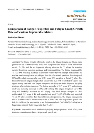
![Materials 2012, 5 2982
1. Introduction
Orthopedic implants should exhibit biomechanical and biochemical compatibility as well as
biological safety. Therefore, many types of metallic orthopedic devices, which are made of metallic
materials with excellent mechanical properties and structural stability, are used worldwide in
orthopedic [1]. Ti alloys are categorized into three types according to their microstructure:
α (alpha)-type alloy having a hexagonal close-packed structure, hcp; β (beta)-type having a
body-centered cubic structure, bcc; and α-β-type having a mixed structure of the α- and β-phases [1].
Among α-β-type Ti alloys, Ti-6Al-4V alloy has various orthopedic applications. α-β-type Ti
alloys demonstrate better fatigue characteristics than β-type alloys [1]. Another α-β-type Ti alloy,
Ti-15Zr-4Nb-4Ta alloy, has been developed in Japan as a highly biocompatible alloy for long-term
biomedical applications [1–3]; it is now standardized in the Japanese Industrial Standards (JIS)
T 7401-4 [4].
Fatigue is a type of damage often observed in implanted metals and is regarded as an important
cause of orthopedic metal implant failure [5–34]. To summarize the literature on causes of failure,
prosthetic fracture occurs owing to fatigue due to stress concentration that develops near holes of
plates and rods, screws, spinal implants, and junctions of artificial hip stems. In particular, the
existence of a notch markedly reduces the fatigue strength of materials. In developing highly durable
devices, testing the fatigue strength of materials is crucial for predicting implant durability. A few
studies have compared fatigue properties among implantable metals using specimens prepared by the
same manufacturing process under the same experimental conditions. As fatigue testing methods,
several standard methods have been established in JIS and the American Society for Testing and
Materials (ASTM). JIS T 0309 [35] and ASTM F 1801 [36] provide methods for investigating the
fatigue of metallic implant materials. JIS T 0310 [37] standardizes the fatigue testing method for the notch
sensitivity and fatigue crack growth properties of metallic biomaterials. Our fatigue test was based on these
standardized testing methods. The fatigue strength and effects of a notch on the fatigue strength and fatigue
crack growth rate of Ti-15Zr-4Nb-4Ta alloy were compared with those of other implantable metals,
namely, commercially pure (C.P.) grade 4 Ti, Ti-6Al-4V, Co-Cr-Mo, Co-Cr-Mo-Ni-Fe, and Co-Cr-W-Ni
alloys, and stainless steels.
In this study, we conducted fatigue tests on smooth and notched specimens, and fatigue crack
growth tests on Ti materials, Co-Cr-Mo, Co-Cr-Mo-Ni-Fe, and Co-Cr-W-Ni alloys, and stainless
steels. The highly biocompatible Ti-15Zr-4Nb-4Ta alloy was used to determine the extent to which the
fatigue strength and fatigue crack growth rate are affected by the specimen configuration (plate or rod),
manufacturing process, heat treatment, and stress intensity factor. To evaluate the effects of forging,
heat treatment, and stress intensity factor on smooth and notched fatigue strengths, the S-N curves
(maximum stress vs. number of cycles) of Ti-15Zr-4Nb-4Ta alloy were compared with those of C.P.
grade 4 Ti, Ti-6Al-4V, Co-Cr-Mo, two types of Co-Cr-Mo-Ni-Fe, and Co-Cr-W-Ni alloys, and
three types of stainless steel. Tensile tests were also carried out on these materials at room temperature
to examine the correlation between their mechanical and fatigue strengths. The effects of an R-notch
and a V-notch on notched fatigue strength were examined. The fatigue crack growth rates of
Ti-15Zr-4Nb-4Ta, Ti-6Al-4V, Co-Cr-Mo-Ni-Fe, and stainless steels were measured. Moreover, the
maximum stress amplitude σth at which no crack propagation occurs, estimated from the threshold](data:image/gif;base64,R0lGODlhAQABAIAAAAAAAP///yH5BAEAAAAALAAAAAABAAEAAAIBRAA7)