4. 4
In recent years, new highly corrosion-resistant
austenitic stainless steels have entered the market-
place. They have demonstrated cost-effective per-
formance in a variety of harsh and corrosive
environments. They have supplied the materials
engineer with alloys for demanding new energy and
environmental needs. These new materials are called
“High Performance Austenitic Stainless Steels”
(HPASS). They obtain their performance through
alloying with higher than usual amounts of molyb-
denum and nitrogen. They are more complex than the
standard stainless steels, and demand that engineers,
1 Introduction
designers, and fabricators have thorough knowledge
of their characteristics in order to specify and
fabricate them successfully. This brochure provides
basic information on HPASS grades and compares
them to the standard grades. Its primary focus is
to compare the fabrication characteristics of the
two groups of steels, and to identify similarities
and differences between them. This information
will help those responsible for fabricating HPASS to
manufacture a high-quality product that will perform
successfully in the field.
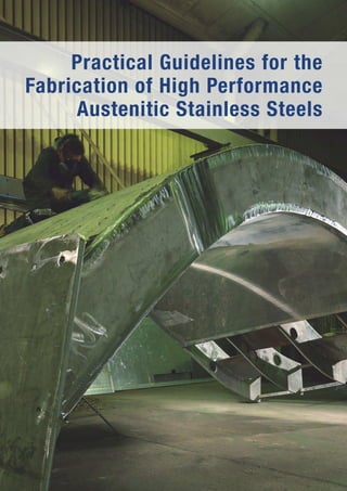
HPASS in a flue gas scrubber application. (Source: Outokumpu)
5. 5
Stainless steels were introduced at the beginning of
the twentieth century as a result of pioneering work
in England and Germany. In the ensuing half century,
manufacturers developed a large family of stainless
steels that has served the chemical, energy, food,
and other industries very well. The modern era
of stainless steels began in the early 1970s when
steelmakers introduced new refining and casting
technologies. These technologies allowed steel de-
signers and producers to both improve existing
“standard grades” and develop new grades with
improved performance, including the new HPASS
grades.
The new steel-making technologies included argon-
oxygen decarburization (AOD) and vacuum-oxygen
decarburization (VOD) processes. They made it
economically possible to achieve very low carbon
content, high alloy recovery, and better composition
control (especially precisely controlled nitrogen con-
tent). Electroslag remelting (ESR), performed as an
alternative or supplemental process, provided im-
proved composition control and a more homogenous
microstructure containing fewer inclusions. Continu-
ous casting increased efficiency, further reducing
production costs.
One of the first alloys to take advantage of the new
technologies, the first member of HPASS, was 904L
(N08904) developed by what is now Outokumpu
Stainless. Grade 904L employs very low carbon
levels to produce a weldable wrought version of an
existing cast alloy having very high resistance to
strong reducing acids. In 1973, ATI Allegheny Ludlum
introduced the first fully seawater-resistant
austenitic stainless steel, AL-6X®, containing 6% Mo
and very low carbon to achieve weldable thin sheet
and tubing products. By the mid-seventies, develop-
ments in the use and control of nitrogen led to
improved 6% Mo alloys that were weldable in thick
sections and resistant to the formation of detrimental
intermetallic phases that reduce pitting resistance.
Representative of these alloys are 254 SMO®
(S31254) by Outokumpu Stainless and AL-6XN®
(N08367) by ATI Allegheny Ludlum.
The increasing need for cost-effective, high-per-
formance alloys in emerging environmental and
energy industries pushed the required corrosion
performance of these stainless steels even higher
in the 1990s. Two alloys having extremely high-
pitting resistance in aggressive chlorinated water
were introduced. Outokumpu Stainless introduced
alloy 654 SMO® (S32654), containing 7.3% Mo and
0.50% N; Industeel developed alloy B66 (S31266),
containing 6% Mo, 2% W and 0.45% N. These steels
approach the performance of some of the highly
corrosion-resistant nickel-base alloys at significantly
lower cost.
Table 1 shows the chemical composition of these new
high performance stainless steels. The alloys contain
chromium, nickel and molybdenum contents well
above those of the standard 18% Cr-8% Ni grades.
Many contain nitrogen additions as well. As market
needs arise and technology improves, more alloys
will certainly be added to this outstanding group of
steels.
2 History of Austenitic Stainless Steels
Heat exchanger tubesheet during fabrication. (Source: Sandvik)
6. 6
Table 1: Chemical composition* of high performance austenitic stainless steels and representative standard grades (wt. pct.)**
Notes:
* Taken from ASTM specifications for plate, sheet and strip when available or from company data sheets. For "other" alloying elements
consult these sources.
** Chemistry maximum, unless range or minimum is indicated, EN chemistry does not correspond exactly to ASTM chemistry
*** Alloy 825 is a nickel base alloy, not a stainless steel.
Registered trade names are listed on page 69.
Grade UNS No. EN No. C N Cr Ni Mo
Representative standard grades
Type 304L S30403 1.4307 0.03 0.10 18.0–20.0 8.0–12.0
Type 321 S32100 1.4541 0.08 0.10 17.0–19.0 9.0–12.0
Type 347 S34700 1.4550 0.08 0.10 17.0–19.0 9.0–13.0
Type 316L S31603 1.4404 0.03 0.10 16.0–18.0 10.0–14.0 2.00–3.00
Type 317L S31703 1.4438 0.03 0.10 18.0–20.0 11.0–15.0 3.00–4.00
Type 309S S30908 1.4833 0.08 0.10 22.0–24.0 12.0–15.0
Type 310S S31008 1.4845 0.08 0.10 24.0–26.0 19.0–22.0
High performance austenitic stainless steels
Alloy 20, 20Cb-3 N08020 2.4660 0.07 19.0–21.0 32.0–38.0 2.00–3.00
Alloy 825*** N08825 2.4858 0.05 19.5–23.5 38.0–46.0 2.50–3.50
317LM S31725 0.03 0.10 18.0–20.0 13.2–17.5 4.00–5.00
317LMN S31726 1.4439 0.03 0.10–0.20 17.0–20.0 13.5–17.5 4.00–5.00
904L N08904 1.4539 0.02 19.0–23.0 23.0–28.0 4.00–5.00
155N S31727 0.03 0.15–0.21 17.5–19.0 14.5–16.5 3.80–4.50
Alloy 28 N08028 1.4563 0.02 26.0–28.0 30.0–34.0 3.00–4.00
4565 S, Alloy 24 S34565 1.4565 0.03 0.40–0.60 23.0–26.0 16.0–19.0 3.00–5.00
20Mo-6 N08026 0.03 0.10–0.16 22.0–26.0 33.0–37.0 5.00–6.70
254N S32053 0.03 0.17–0.22 22.0–24.0 24.0–26.0 5.00–6.00
25-6MO, 1925 hMo N08926 1.4529 0.02 0.15–0.25 19.0–21.0 24.0–26.0 6.00–7.00
254 SMO S31254 1.4547 0.02 0.18–0.22 19.5–20.5 17.5–18.5 6.00–6.50
AL-6XN N08367 0.03 0.18–0.25 20.0–22.0 23.5–25.5 6.00–7.00
UR 66 S31266 1.4659 0.03 0.35–0.60 23.0–25.0 21.0–24.0 5.00–7.00
27-7MO S31277 0.02 0.30–0.40 20.5–23.0 26.0–28.0 6.50–8.00
3127 hMo, Alloy 31 N08031 1.4562 0.02 0.15–0.25 26.0–28.0 30.0–32.0 6.00–7.00
354N N08354 0.03 0.17–0.24 22.0–24.0 34.0–36.0 7.00–8.00
654 SMO S32654 1.4652 0.02 0.45–0.55 24.0–26.0 21.0–23.0 7.00–8.00
7. 7
3 Metallurgy
3.1 Types of stainless steels
Stainless steels are iron-based alloys containing
at least 10.5% Cr, which are used primarily for
their corrosion resistance. At this chromium level, a
chromium-enriched surface oxide, called the passive
layer or passive film, forms on the steel. It protects
the stainless steel and keeps it from “rusting” like
ordinary steel. There are many different stainless
steels, but they all meet this minimum chromium
requirement. Stainless steels belong to one of four
major categories: austenitic, ferritic, duplex (mixed
ferritic and austenitic), and martensitic. The cate-
gories are related to the steels’ crystal structure (its
arrangement of atoms) and their heat treatment.
As the name indicates, HPASS are in the austenitic
category. They have a face-centered cubic (fcc)
crystal structure, so called, because the atoms are
located at corners and face centers of a cubic lattice.
They usually contain nickel and chromium, are very
ductile, and cannot be hardened by heat treatment.
Ferritic steels have a body-centered cubic (bcc)
crystal structure with atoms located at the corners
and centers of a cubic lattice. They usually have low
nickel content and can also not be hardened by heat
treatment. Duplex steels contain roughly equal
portions of the ferrite and austenite structures and
offer properties between those provided by ferritic
and austenitic steels. Martensitic steels are those
that can be hardened by heat treatment.
3.2 Phase balance
In a metal, groups of crystals having the same
crystal structure are called phases. The phase names
for the three crystal structures present in stainless
steels are austenite, ferrite, and martensite. The
metallurgist uses a technique of polishing and
etching the surface of a small sample to identify and
quantify the phases present. A representative HPASS
microstructure will display a collection of austenite
“grains” – groups of fcc crystals – that are free of
other phases (Figure 1).
The metallurgist uses chemical composition and heat
treatment to control the quantity and type of phases
present in the steel. Ferrite-forming elements foster
formation of ferrite, while austenite-forming elements
promote the formation of austenite. Table 2 lists the
common ferrite and austenite forming elements.
The “phase balance” (relative amounts of different
phases) of a steel determines its properties. Con-
trolling the steel’s phase balance, and therefore
its properties, demands a balance of the alloying
elements. The Schaeffler Diagram (Figure 2) is a tool
that shows the relationship between the chemical
composition and the phases present in a stainless
steel in the as-cast condition, as might be found in
a weld. It allows the user to determine the phase
balance from a given specified composition. A typical
HPASS containing about 20% Cr, 6% Mo, 20% Ni
and 0.2% N, will be located on the diagram in the
single-phase Austenite region, near the No Ferrite
line at the Nickel Equivalent of about 24 and a
Chromium Equivalent of about 26. Ferritic steels are
designed to fall within the Ferrite region of this
diagram, and duplex steels fall within the two-phase
austenite + ferrite (A+F) region. The diagram shows
that minor variations in carbon or silicon content can
have a great effect on the phase balance.
Figure 1: Microstructure of austenitic stainless steel consisting of austenite grains free of
precipitates and other phases.
Table 2: Alloy additions that promote formation of ferrite
and austenite.
Ferrite formers Austenite formers
Iron Nickel
Chromium Nitrogen
Molybdenum Carbon
Silicon Manganese
Niobium (Columbium) Copper
Aluminum Cobalt
Titanium
Tungsten
8. 8
3.3 Secondary phases –
intermetallic compounds
The ideal microstructure of standard and HPASS is a
homogeneous array of austenite grains without any
secondary phases. However, this is in most cases
not the equilibrium condition for austenitic steels.
Other, secondary phases can form in the austenitic
structure when stainless steels are exposed
to elevated temperatures, and they are usually
detrimental to properties. The producer or the
fabricator must closely control annealing treatments
and other fabricating parameters to avoid formation
of these secondary phases. The HPASS are very
susceptible to secondary phase formation because
of their high alloy content. Therefore, a thorough
understanding the formation and control of these
phases is essential to the successful use of HPASS.
Carbides and nitrides of chromium are of concern
because they tend to form in austenite grain bound-
aries and reduce corrosion resistance there. Two
other important secondary phases are sigma and chi.
These phases are called intermetallic compounds
because they are more like a chemical compound
than a metal. They contain very high chromium and/
or molybdenum content, are brittle and can reduce
corrosion resistance by depleting surrounding areas
of chromium or molybdenum. The following sections
discuss conditions that lead to their formation and
control.
3.3.1 Temperature of secondary phase
stability
At sufficiently high temperatures, up to near the
melting point, a single austenite phase structure is
the equilibrium condition for both the standard
grades and most HPASS. At some lower temperature
that depends on the steel’s composition, one or more
secondary phases, sometimes called precipitates,
may want to form in an attempt to reach equilibrium.
This lower temperature is normally the lower limit of
the solution annealing temperature range for any
given steel.
In the standard grades, chromium carbide, (Cr23C6)
is the primary concern. In Type 304 for example, it
starts to form below about 900°C (1650°F). With
higher alloy content, the tendency to form other sec-
ondary phases increases, as does the temperature
for their formation. In some of the very highly alloyed
HPASS, chi phase can form at about 1095°C (2000°F).
This means that HPASS must be solution annealed at
much higher temperatures than standard grades,
usually above 1095°C (2000°F). This requirement
must be respected to anneal HPASS successfully.
3.3.2 Kinetics of secondary phase
formation
The kinetics of secondary phase formation, in other
words, the rate at which secondary phases form on
cooling, is a very important factor to consider for the
successful annealing and welding of these steels.
Regardless of grade, stainless steels must be cooled
rapidly enough to avoid the formation of secondary
phases. To illustrate the relationship between cooling
rate and grade, consider the case of standard Type
304 stainless steel and its most likely secondary
phase, chromium carbide. Chromium carbide is stable
and begins to form on cooling at temperatures below
about 900°C (1650°F). The rate at which it forms
is slow just below 900°C (1650°F), increasing
rapidly with decreasing temperature until at about
Figure 2: The Schaeffler Diagram shows the influence of chemical composition on the amount of ferrite and austenite in
the microstructure of as-cast weld metal. (1)
0
0
4
8
12
16
20
24
28
32
4 8 12 16 20 24 28 32 36 40
F
+
M
A + M
A + F
A + M + F
M + F
Martensite
Austenite No Ferrite
5%
Ferrite
10%
Ferrite
20%
Ferrite
40% Ferrite
80% Ferrite
100% Ferrite
Ferrite
Chromium equivalent = %CR * %Mo + 1.5 x %Si + 0.5 x %Cb
Nickelequivalent=%Ni+30x%C+0.5xMn
9. 9
700°C (1300°F), where it is very high. Therefore Type
304 must be cooled very rapidly to a temperature
somewhat below 700°C (1300°F) to avoid carbide
formation and obtain an acceptable annealed or
welded microstructure.
If cooling is not rapid enough, chromium carbides
form on the boundaries of the austenite grains.
Extensive precipitation creates a continuous network
of carbides along the grain boundaries. To form
chromium carbides, carbon and chromium from
the stainless steel matrix combine and precipitate
on the grain boundary (where there is more space
to form than in the grain). The area right around
the carbides, along the grain boundaries, therefore
has lower chromium content than the bulk material
consequently a lower corrosion resistance. The
phenomenon, known as “sensitization,” is well known
and understood. Figure 3 illustrates a sensitized
microstructure, schematically showing grain bound-
ary precipitates and the associated chromium-
depleted zone. Similar phenomena occur with other
secondary phases but the temperatures and times
involved are different.
The kinetics of secondary phase formation can be
described by Time-Temperature-Transformation (TTT)
curves for any given alloy. The curves are obtained by
first heating test samples to some high temperature
(the solution annealing temperature) to dissolve all
secondary phases. The samples are then rapidly
cooled to an intermediate temperature of interest,
held there for various lengths of time, and again
rapidly cooled to room temperature to “freeze” the
intermediate-temperature structure. The secondary
phases are quantified by metallographic or x-ray
techniques, and the resulting data describing the
formation and growth of the secondary phases are
plotted on charts of temperature versus elapsed
holding time. The samples can also be subjected to
corrosion tests appropriate for the intended service
conditions, and the corrosion data plotted in a similar
fashion. In this case, the resulting curves are called
Time-Temperature-Sensitization (TTS) curves.
Figure 4 shows TTT curves for a number of Type 304
stainless steels with a variety of carbon contents,
which reveal several things. Above about 900°C
(1650°F) the steels remain completely austenitic.
Between about 540°C and 900°C (1,000°F and
1,650°F), the time to begin precipitation varies by
more than an order of magnitude. Chromium carbide
precipitation kinetics is much slower in steels with
lower carbon contents. From a practical standpoint,
the curves show that when annealing or welding
these steels with, they must be cooled rapidly below
the nose of the curves to avoid sensitization and the
associated danger of localized corrosion. Lowering
the carbon content extends the available time for
cooling, making it easier to avoid sensitization.
Figure 3: Schematic representation of sensitized grain
boundaries in an austenitic stainless steel. (2)
Figure 4: TTS diagram for Type 304 stainless steel with various carbon contents. (3)
Figure 5: TTT diagram for Type 316 stainless steel. Secondary phases chi, sigma and Laves
take a long time to develop in this standard grade stainless steel. (4)
Chromium carbide
precipitate
Grain boundaries
Chromium
depleted zone
800
1000
1200
1400
1600
900
°F °C
0.080 0.062
0.056
0.058
0.052
0.042
0.030
0.019%
carbon
700
600
500
10 sec. 1 min. 10 min. 1 h 10 h 100 h 1000 h 10000 h
800
200
0.1 1 10 100 1000 10000
2012
1832
1652
1472
1292
1112
932
752
572
392
300
1100
1000
900
800
700
600
500
400
Temperature°C
Temperature°F
Carbide
Chi
Sigma
Laves
Time (minutes)
10. 10
Chromium carbide precipitation in standard grades is
well understood. Information on required cooling
rates for different section sizes is available and
alternative alloys exist to meet special situations.
These include low carbon grades (Types 304L and
316L), stabilized grades (Types 321 and 347), and
nitrogen modified standard grades that use nitrogen
additions to retard the chromium carbide precipitation
rate.
With HPASS, precipitation of sigma and chi phases is
of greater concern than chromium carbide, because
the high chromium and molybdenum content in the
alloys promotes rapid formation of these phases. All
HPASS have low carbon content, which minimizes the
rate of chromium carbide formation and reduces
concern for chromium carbide sensitization. A TTT
diagram for Type 316 stainless containing 2% Mo and
a fairly high carbon content (Figure 5), shows that
chromium carbide can form in as little as five
minutes, but chi and sigma phases only form after
80 hours or so. In contrast, an alloy having similar
chromium and nickel content, but containing 5% Mo,
suffers chi formation in very short times (Figure 6).
The time for chi formation in the 5% Mo alloy is even
shorter than that for chromium carbide formation.
As briefly noted earlier, nitrogen delays the formation
of these phases, and is employed for this purpose in
many HPASS. This effect is demonstrated in Figure 7.
In this figure, the 5% Mo alloy of Figure 6 is modified
with 0.145% N. The nitrogen addition pushes back
the onset of both chi and chromium carbide forma-
tion to ten minutes, compared to two to four minutes
for the alloy containing only 0.039% N. The 0.145% N
alloy allows for slower cooling after annealing or
welding without the formation of secondary phases.
As chromium and molybdenum increase to very high
levels in the most highly alloyed HPASS, intermetallic
phases form at even shorter times. Nitrogen additions
are helpful, but even very high nitrogen contents
of 0.20-0.50% N are not able to shift the onset of
precipitation to times in the desired range of ten
minutes or more. Figure 8 shows representative TTT
curves of several alloys to illustrate this point. Type
317LMN, (17% Cr, 14% Ni, 4.5% Mo, 0.15% N) forms
secondary phases in about the same time as 316 de-
spite its higher alloy content, due to the effect of ni-
trogen. Alloy 254 SMO (20% Cr, 18% Ni, 6% Mo,
0.20% N), begins to suffer precipitation in about 30
seconds, and alloy 904L (20% Cr, 25% Ni, 4.55% Mo,
no nitrogen addition) suffers intermetallic phase for-
mation in less than one minute. Clearly, alloys
of this kind require limitations on section size or
drastic cooling to avoid secondary phase formation.
Figure 7: TTT diagram for the same alloy as in Figure 6 but with 0.145% N. (4)
Figure 6: TTT diagram for a 0.05C-17Cr-13Ni-5Mo stainless with 0.039% N. (4)
Temperature°CTemperature°C
Temperature°FTemperature°F
Carbide
Carbide
Chi
Chi
Sigma
Laves
Laves
Temperature°C
Temperature°F
Type 316
904 L
254 SMO
371 LMN
Figure 8: TTT diagram for several commercial austenitic stainless steels with different
molybdenum and nitrogen contents. (4)
200
300
1100
1000
900
800
700
600
500
400
200
300
1100
1000
900
800
700
600
500
400
200
300
1100
1000
900
800
700
600
500
400
2012
1832
1652
1472
1292
1112
932
752
572
392
2012
1832
1652
1472
1292
1112
932
752
572
392
2012
1832
1652
1472
1292
1112
932
752
572
392
0.1 1 10 100 1000 10000
Time (minutes)
0.1 1 10 100 1000 10000
Time (minutes)
0.1 1 10 100 1000 10000
Time (minutes)
11. 11
4 Role of Alloying Elements
Chemical composition has a major influence on a
steel’s metallurgical structure, mechanical properties,
physical properties and corrosion resistance. Both
intentional alloying elements and alloying elements
unintentionally introduced by the steelmaking
process affect these properties.
Alloying elements other than carbon and nitrogen, for
example chromium and nickel are incorporated in the
crystal lattice on substitutional sites. That is, they
substitute for iron on the corners and face centers of
the austenitic lattice. Carbon and nitrogen, because
of their small size, locate themselves in open spaces
(interstitial sites) between the lattice atoms. In doing
so, they create large strains in the lattice and so are
potent hardening elements.
Alloying elements influence the steel’s properties
in different ways, sometimes beneficial, sometimes
detrimental. Choosing a particular steel composition
often requires the designer or materials engineer
to sacrifice a measure of one property to maximize
the benefit of another. The following sections
describe the function of important alloying elements
in austenitic stainless steels.
4.1 Chromium (Cr)
Chromium is the alloying element that makes stainless
steels “stainless”. At least 10.5% Cr is required to
produce the unique surface passive film responsible
for this characteristic. The passive film is effective in
protecting the stainless steel in environments that
can include aggressive waters, many acids and even
highly oxidizing high-temperature gases. Corrosion
resistance improves in a wide variety of environments
as chromium increases above the threshold level of
10.5%. For this reason many grades have chromium
levels well above that amount. Examples are the
workhorse Type 304 grade with 18% Cr and the
HPASS with 20–28% Cr.
4.2 Nickel (Ni)
Nickel’s primary purpose is to create and stabilize
austenite. Without 8% Ni, Type 304 would not be an
austenitic stainless steel and would not exhibit
austenite’s desirable mechanical properties. Instead,
it would be a ferritic stainless steel with serious
limitations in strength and toughness. As more
chromium or other ferrite-forming elements are
added to the steel, more nickel is needed to maintain
the austenitic structure. The HPASS, which have high
chromium and molybdenum, require nickel contents
of 20% or more to preserve the austenitic structure.
Nickel also improves corrosion behavior in certain
reducing acids, and increases stress corrosion
resistance at levels above about 20%. It also reduces
the rate of work hardening during cold deformation,
so it is often found in alloys designed for deep drawing,
spin forming and cold heading.
4.3 Molybdenum (Mo)
Molybdenum increases resistance to pitting and
crevice corrosion in chloride-containing environments.
It works synergistically with chromium and nitrogen
to improve performance in these environments. This
synergistic effect produces very high pitting and
crevice corrosion performance in HPASS. Molybdenum
also increases corrosion resistance in reducing
environments like hydrochloric acid and dilute sulfuric
acid. The minimum molybdenum addition to austenitic
stainless steels is about 2%, as in Type 316. The most
highly alloyed HPASS steels contain up to 7.5% Mo.
Molybdenum promotes ferrite formation, which affects
phase balance. It participates in the formation of
several detrimental secondary phases, and forms an
unstable high temperature oxide, adversely affecting
high temperature oxidation resistance. These factors
must also be considered in using stainless steels
containing molybdenum.
4.4 Carbon (C)
Carbon strengthens austenite, so it is a useful alloying
element in stainless steels used in applications like
boiler tubes that operate at high temperature.
Carbon has no other useful function and can be
detrimental to corrosion resistance under certain
circumstances as noted earlier. The carbon content
of most austenitic stainless steels is usually limited
to the lowest practical levels.
Standard low carbon grades designed for welding
(Types 304L and 316L) limit carbon to 0.030%. Some
of the more highly alloyed high performance grades
limit carbon even further to 0.020%.
4.5 Nitrogen (N)
Nitrogen stabilizes and strengthens austenite, and
retards secondary phase formation. It is used in
both standard grades and in HPASS. In low carbon
standard grades, it is added in small amounts (about
0.1%) to offset the loss in strength due to the low
carbon. In standard grades and HPASS, it provides
strength and retards carbide sensitization and
the formation of secondary phases. Nitrogen also
improves resistance to chloride pitting and crevice
corrosion, so some of the most corrosion resistant
HPASS contain up to 0.5% N.
12. 12
4.6 Manganese (Mn)
Steelmakers use manganese to deoxidize molten
steel, so a small residual amount is found in all
stainless steels. Manganese serves an alloying
function because it stabilizes austenite. Addition-
ally, it increases nitrogen solubility in the stainless
steel, so it is added to many HPASS to allow higher
nitrogen content and improved strength and corro-
sion resistance.
4.7 Copper (Cu)
Copper improves the corrosion resistance of stainless
steels in reducing acids like certain sulfuric acid and
phosphoric acid mixtures. It is used as an alloying
element in some HPASS that have been designed
specifically for service in these environments.
4.8 Silicon (Si)
Like manganese, silicon is used to deoxidize molten
steel, so a small amount is always present as small
oxide inclusions containing silicon, manganese and
other deoxidizing elements. These inclusions can have
subtle effects on the surface quality, polishability,
weldability and corrosion resistance of stainless steel
products.
4.9 Niobium/columbium
(Nb/Cb) and titanium (Ti)
These elements are very strong carbide formers,
and are used as alternatives to low carbon content
to mitigate sensitization. They also confer high
temperature strength. Types 347 and 321 containing
Nb and Ti are often used in boiler and refinery
applications where elevated temperature strength
and weldability are requirements. They are also used
in certain deoxidation practices, so sometimes are
found as residual elements in HPASS.
4.10 Sulfur (S) and
phosphorus (P)
Sulfur has both beneficial and detrimental effects on
the properties of stainless steels. Its most important
beneficial effect is improved machinability, while its
major detrimental effect is reduced hot workability.
The HPASS are intrinsically difficult to hot work, so
they always contain lowest practical sulfur content,
about 0.001%. Sulfur is not normally used as an alloy
addition to these steels.
Phosphorous has no beneficial effect, and is detri-
mental to hot workability during forging and hot
rolling. It also promotes hot cracking during cooling
after welding. It is always limited to the lowest prac-
tical level.
Type 316L stainless steel portable vessel and control panel for the bio-pharmaceutical industry.
(Source DCI, Inc, St. Cloud, MN USA)
13. 13
5 Mechanical and Physical Properties
The HPASS retain the overall good mechanical
properties of the standard grades, delivering some-
what higher strength and slightly lower ductility in
the annealed condition. Cold work significantly
increases their strength. Because they work harden,
they have excellent formability and can absorb large
amounts of energy before failure. Their strength
derives from solution-hardening effects of both
substitutional alloying elements and interstitial
nitrogen. These alloys retain good mechanical prop-
erties at low and high temperatures.
5.1 Strength
Table 3 summarizes room temperature mechanical
properties for HPASS. The higher yield and tensile
strength values are due largely to nitrogen and
carbon strengthening effects. Figure 9 summarizes
the effect of nitrogen on strength for a number of
austenitic stainless steels. Increasing nitrogen
content from the normal 0.05% to 0.20% raises
yield strength from 270 MPa (39 ksi) to 340 MPa
(49 ksi). This has a significant effect on specification
minimums. ASTM A 240 specifies a minimum yield
strength of 170 MPa (25 ksi) for Type 304L (about
0.05% N), and 240 MPa (35ksi) for Type 304N
(0.15% N). A further step-up occurs for HPASS grades
like S31254 (0.20% N) with a specified minimum
yield strength of 310 MPa (45 ksi) and S31266
(0.50% N) with a minimum yield strength of 420 MPa
(61 ksi).
Austenitic stainless steels cannot be hardened by
heat treatment, so they are usually produced in
the annealed condition. Cold work increases their
strength, therefore, some mill products are produced
in the cold rolled condition when higher strength is
required. The HPASS respond to cold working as the
standard grades do. Cold working processes like
forming, spinning, swaging, and cold drawing can
produce very high strength. Nitrogen increases the
effectiveness of cold working, so even higher
strength results when these alloys are cold worked
Figure 9: Effect of nitrogen on the strength of austenitic stainless steels. (5)
1200
1100
1000
900
800
700
600
500
400
300
200
100
0
0 0.2 0.4 0.6 0.8 1.0 1.2 1.4 1.6
Nitrogen content (weight - percent)
Yieldstrength,ultimatetensilestrength,(MPa)
(Figure 10) compared to standard grades. This strong
work-hardening effect can cause difficulty in some
shop-forming operations where a section size limita-
tion might occur for a given machine power. High
work hardening rates can also create problems dur-
ing machining if the cutting tool hardens the
surface of the work piece. Low speeds and large
depth of cut are recommended when machining
HPASS.
The yield strength of cold-worked nitrogen alloyed
material can be further increased by a strain ageing
process, where the steel is aged for about ten
minutes at temperatures of 300 to 500°C (570 to
930°F).
The strength imparted by cold work is retained at
moderate temperatures, but not at high tempera-
tures. So, a cold-worked material does not retain
its strength upon annealing or traditional fusion
welding. Specialized spot welding techniques can
circumvent this limitation, and are used in applica-
tions like rail cars that use cold-worked sheet.
Ultimate tensile strength
Yield strength
14. 14
Table 3: Minimum mechanical properties of standard and high performance austenitic stainless steels.
Note: These mechanical properties correspond to the grades of ASTM produced to the UNS designations shown. The grades identified by
Euro Norm designation, as shown in the second column, are similar but may not be identical. Material certified as meeting the requirements
of a specification within one system, e.g., ASTM, will not necessarily meet the requirements of the similar material in another specification,
e.g., EN or JIS.
* Alloy 825 is a nickel base alloy, not a stainless steel.
Grade UNS No. EN No. Yield strength 0.2% Tensile strength Elongation in 2’’ Hardness, max
MPa (ksi) MPa (ksi) % Brinell Rockwell B
Chromium-nickel austenitic stainless steels
Type 304L S30403 1.4307 170 (25) 515 (75) 40 201 92
Type 321 S32100 1.4541 205 (30) 515 (75) 40 217 95
Type 347 S34700 1.4550 205 (30) 515 (75) 40 201 92
Type 316L S31603 1.4404 170 (25) 515 (75) 40 217 95
Type 317L S31703 1.4438 205 (30) 515 (75) 35 217 95
Type 309S S30908 1.4833 205 (30) 515 (75) 40 217 95
Type 310S S31008 1.4845 205 (30) 515 (75) 40 217 95
High performance austenitic stainless steels
Alloy 20, 20Cb-3 N08020 2.4660 240 (35) 550 (80) 30 217 95
Alloy 825* N08825 2.4854 310 (45) 655 (95) 30
317LM S31725 205 (30) 515 (75) 40 217 95
317LMN S31726 1.4439 240 (35) 550 (80) 40 223 96
904L N08904 1.4539 220 (31) 490 (71) 35 90
155N S31727 245(36) 550(80) 35 217
Alloy 28 N08028 1.4563 500 (73) 214 (31) 40 90
4565 S, Alloy 24 S34565 1.4565 415 (60) 795 (115) 35 241 100
20Mo-6 N08026 241 (35) 551 (80) 30 217 95
254N S32053 295 (43) 640(93) 40 217 96
25-6MO, 1925 hMo N08926 1.4529 295 (43) 650 (94) 35
254 SMO S31254 1.4547 310 (45) 655 (95) 35 223 96
AL-6XN N08367 310 (45) 655 (95) 30 241
UR 66 S31266 1.4659 420 (61) 750 (109) 35
27-7MO S31277 360 (52) 770(112) 40
3127 hMo, Alloy 31 N08031 1.4562 276 (40) 650 (94) 40
354N N08354 295 (43) 550(80) 40 217 96
654 SMO S32654 1.4652 430 (62) 750 (109) 40 250
15. 15
5.2 Ductility and toughness
The HPASS have ductility similar to the standard
grades, with elongation values in the range of 60%
to 70%, well above specification minimums. The
nitrogen used to increase strength in some of these
alloys does not reduce ductility.
The face-centered-cubic crystal structure of austenite
is responsible for the good ductility and high-work
hardening rates of these steels, which in turn produce
very good toughness at ambient temperature and
below. Unlike carbon steels and some other materials,
austenitic alloys do not exhibit a ductile-to-brittle
transition as temperature is reduced. However, some
of the most highly alloyed HPASS containing high
nitrogen display a somewhat greater loss in toughness
at cryogenic temperatures than lower alloyed
austenitic stainless steels.
Cold work has a strong effect on ductility and tough-
ness. It decreases ductility by depleting the ductility
reservoir of the annealed starting material. Annealing
erases the effects of cold working, reducing strength
and restoring ductility and toughness to high values.
5.3 High-temperature strength
Austenitic stainless steels deliver good strength at
elevated temperatures. Most of the standard grades
have been approved for pressure vessel applications.
The ASME Pressure Vessel Code gives allowable
design values to temperatures up to 427°C (800°F).
For furnace applications, where pressure is not a
factor, standard and some special heat resistant
stainless alloys are used at twice these temperatures.
The HPASS are designed primarily for corrosion
resistance, but they also have good high-temperature
strength. Their strength advantage over standard
grades at ambient temperature is retained at high
temperature. For example, the ASME Code allowable
stress at 427°C (800°F) for HPASS N08367 is 18 ksi
(124 MPa), compared to Type 316 at 9.6 ksi (66 MPa).
Figure 11 compares high-temperature strength data
for Type 316 to three HPASS.
Figure 10: Effect of cold work on the strength and ductility of a 6% Mo – 0.2% N HPASS. (6)
0
1400
Tensile strength
Yield strength
Elongation
1200
1000
800
600
400
200
0
20
20
40
40
60
60
Cold work (%)
Yieldstrength,tensilestrength(MPa)
Elongation(%)
The austenitic stainless steels retain their strength
at high temperatures much better than ferritic
stainless steels because of their crystal structure and
their high nickel contents. They are very useful at
elevated temperatures because they do not form the
embrittling alpha prime phase above about 300°C
(570°F), but they can form the embrittling chi and
sigma phases at temperatures in the 500-1050°C
(930-1925°F) range.
High strength has positive and negative effects
on fabrication of these alloys. When annealing a
fabricated component, high strength at temperature
prevents distortion under the influence of gravity.
However, if a component does distort, for example
during welding, high strength makes it more difficult
to straighten the component than if it had lower
strength. As noted earlier, high-strength alloys may
tax the available forming equipment power, limiting
the section size that a given machine can form.
16. 16
5.4 Physical properties
The HPASS have physical properties similar to the
standard austenitic grades when compared to carbon
steels. That is, they have a slightly lower Young’s
modulus, higher coefficient of thermal expansion
Figure 11: High temperature strength of three HPASS compared to Type 316L. (4)
900
800
700
600
500
400
300
200
100
0
32
0
°F
°C
392
200
752
400
1112
600
1472
800
130
116
101
87
73
58
44
29
15
0
Strength(MPa)
Strength(ksi)
Temperature
Tensile strength
T316L
T317LN
20Cb - 3
AL - 6XN
Yield strength
T316L
T317LN
20Cb - 3
AL - 6XN
(CTE) and lower thermal conductivity. Tables 4 and
5 summarize detailed physical property data for
austenitic stainless steels.
20. 20
6 Corrosion Resistance
The HPASS provide the highest corrosion resistance
obtainable with stainless steels. While each alloy has
different attributes, they all are outstanding in one
or more of the three main areas of corrosion
performance: general corrosion, pitting and crevice
corrosion, and stress corrosion cracking.
The passive film on HPASS is strengthened with
molybdenum. Even so, it can break down under
adverse environmental conditions, allowing corrosion
to begin. Widespread film breakdown results in
corrosion across the entire surface (general corrosion).
Localized film breakdown produces pitting corrosion.
Because of molybdenum’s presence, the film on
HPASS is more resistant to breakdown than it is for
the standard grades.
The materials engineer must select the most cost-
effective grade of stainless steel that will maintain
the passive film in the environment of interest. The
fabricator and user must understand the factors
that reduce the alloy’s basic resistance through poor
fabrication or operating conditions. This section
presents some basic principles related to stainless
steel corrosion resistance. Detailed information on
the corrosion performance of stainless steels can be
found in resources cited in the Appendix.
6.1 General corrosion
General corrosion is a uniform metal loss from the
surface that produces a uniform thinning of the
cross-section. With stainless steels it usually occurs
in strong, warm acids. General corrosion usually
indicates that the environment is too aggressive for
the grade selected. If the environment is oxidizing,
a grade having more chromium will often give
better performance. If the environment is reducing,
grades with higher chromium, nickel, molybdenum,
and copper will perform better. Small amounts of
contamination can substantially change the aggres-
siveness of service environments, affecting their
relative oxidizing or reducing powers. Such changes
can correspondingly affect the stainless steel’s
corrosion performance.
6.2 Localized corrosion
6.2.1 Pitting and crevice corrosion
Pitting and crevice corrosion occur in a localized area
on the surface of a metal. There are many ways that
the passive film can be disrupted locally, so these
forms of corrosion are the most likely to occur.
By definition, pitting occurs on a relatively clean,
unblemished surface. Crevice corrosion occurs in a
crevice – for example, underneath a bolt or scale.
These kinds of corrosion are particularly threatening
because they often occur in a seemingly benign
environment and, once initiated, can penetrate very
rapidly.
Resistance to localized attack increases with higher
Cr, Mo and N content, which accounts for the large
amounts of these alloying additions in HPASS.
Environmental conditions that promote pitting and
crevice corrosion include halide ions (especially
chloride), oxidants like manganese, high tempera-
tures, and acid conditions not aggressive enough
to produce general attack. Detrimental design or
operating conditions include built-in crevices like
bolted joints, and deposits related to poor system
cleanliness like scaled surfaces. Careless fabrication
practices can also promote localized corrosion by
creating dirty or blemished surfaces that initiate
corrosion. Occasionally, poor internal steel clean-
liness and certain undesirable nonmetallic inclu-
sions or intermetallic phases can nucleate localized
corrosion.
The HPASS deliver the highest possible pitting and
crevice corrosion resistance for a given set of cost
and fabricability requirements. Laboratory pitting
and crevice corrosion tests in highly corrosive solu-
tions are used to rank different alloys for relative
resistance and to assist in the development of im-
proved alloys. Most of these tests use temperature
as the ranking criterion for a given set of test en-
vironment conditions. The ranking is expressed in
terms of the critical pitting temperature (CPT) or
critical crevice temperature (CCT). The critical tem-
perature is the temperature at which corrosion will
begin to occur as temperature increases (thus a
higher critical temperature is better than a lower
one). A given alloy’s CCT is always lower than its
CPT because crevice corrosion initiates more easily
than pitting corrosion. Figure 12 shows critical
crevice and pitting temperatures measured in a
ferric chloride solution for a number of stainless
steels. Note the superior performance of HPASS
compared to standard Type 316 stainless.
The ranking tests and resultant critical temperatures
do not predict in detail how an alloy will perform
in a given environment, but alloys with higher CCT
or CPT generally have better corrosion resistance
over a range of real environments. Field experience
allows some general correlations between the critical
temperatures and field performance. Type 316L, with
an ASTM G48 CPT of 10°C (50°F), is not suitable for
steam condenser tube service in seawater. HPASS
alloy 254 SMO, with a CPT of 75°C (167°F), gives
satisfactory service in this environment.
21. 21
6.2.2 Effect of secondary phases on
localized corrosion
While austenitic stainless steels are single-phase
alloys, they always contain other minor phases that
are the normal result of steelmaking. The phases
present include oxide and sulfide inclusions from the
steel refining practice in the melt shop, ferrite re-
sulting from phase separation during solidification,
and carbide, chi and sigma phases that can form
during annealing or welding. These phases represent
discontinuities on the steel surface, and they can
facilitate pitting or crevice corrosion because they
disrupt the passive film. Pickling and passivation
treatments often remove them from the surface and
minimize their effect.
When sigma and chi phases form however, they can
present problems in certain circumstances. They
result from alloy element segregation during initial
solidification of the steel, and can also form during
subsequent thermal treatments like annealing
or welding as discussed in Section 3.3. Since they
contain large amounts of chromium and molyb-
denum, they deplete the surrounding area in alloying
elements and reduce corrosion resistance. If they
form during steelmaking they usually are not detri-
mental, subsequent rolling and annealing processes
homogenize the structure and dissolve the inter-
metallic phases. However, if they form during shop
welding or annealing, they can be very detrimental.
Figure 12: Critical pitting and crevice corrosion temperatures for stainless steels and nickel alloys. (4)
110
CCT(°C)
CPT(°C)
304
Temperature(°C)
316 317L 317LMN 904L 254 SMO 654 SMO 2304 2205 255 2507 Alloy G 625 C276
100
90
80
70
60
50
40
30
20
10
0
-10
-20
22. 22
Figure 13 illustrates the temperatures and times over
which precipitation of sigma and chi will begin to
occur in a 6% Mo HPASS. In this figure the formation of
secondary phases is detected by determining
the critical pitting temperature for samples treated
isothermally for various time/temperature combina-
tions. Using the criterion that a CPT<85°C (185°F) is
unacceptable, only very short times at 700°C
(1290°F) can be tolerated before pitting resistance is
degraded. Thus, annealing and welding cycles must
be controlled carefully to avoid secondary phase
precipitation that degrades corrosion resistance. A
small amount of precipitate can be tolerated if a
lower CPT is allowed. If these phases have formed,
they can be eliminated by a full solution annealing
treatment that dissolves them and restores the
alloy’s corrosion resistance.
6.2.3 Stress corrosion cracking
In most alloys, a combination of stress and specific
environment will cause a kind of corrosion known
as stress corrosion cracking (SCC). This form of
corrosion usually occurs as narrow branching cracks
that penetrate across grain boundaries (Figure 14).
With stainless steels, this usually takes place in
chloride-containing environments, and is called
chloride stress corrosion cracking (CSCC).
In order for SCC to occur, some form of tensile stress
must be present along with the specific corrosive
environment. The source of stress can be service
Figure 13: Effect of temperature on the time to start corrosion in a 6% Mo austenitic stain-
less steels as evaluated by critical pitting temperature.
Figure 14: Branching transgranular stress corrosion cracks
in an austenitic stainless steel.
1100
1000
900
800
700
600
500
400
300
200
0.1 1.0 10 100 1000 10000
Time (minutes)
Temperature(°C)
stresses or residual stress due to fabrication
processes. Since residual stresses frequently are
quite high, they often are a factor in SCC. The
standard austenitic stainless steels, including Types
304 and 316, are very susceptible to this form of
corrosion. The HPASS are quite resistant to it.
6.2.3.1 Chloride stress corrosion cracking (CSCC)
When CSCC occurs in an annealed austenitic
stainless steel, it exhibits transgranular cracks with
a morphology determined by the stress pattern.
Sensitization increases SCC susceptibility and
promotes intergranular cracking. High stress,
high temperature, high chloride, and low pH all
increase the likelihood of stress corrosion cracking.
Figure 15 presents a summary of available CSSC
data for Types 304 and 316. In neutral waters, the
chloride content required to produce cracking in
these alloys at temperatures near boiling or higher is
less than 1 ppm. At lower temperatures, near ambient,
stress corrosion failures will still occur but at
somewhat higher chloride levels – in the range of
1–10 ppm and above. Conditions that concentrate
chlorides, like alternate wet/dry surfaces under
insulation, can cause CSCC even when the nominal
environment contains only a few ppm chloride.
The austenitic stainless steels that contain nickel
above the 8-12% range of Types 304 and 316 all
deliver substantially better CSCC performance. The
HPASS, which benefit from their greater chromium
and molybdenum contents as well as higher nickel,
are particularly resistant to CSCC. For example, in
alloy UNS N08367 (AL-6XN) (Figure 15), cracking
does not begin until much higher temperature and
chloride levels. The temperature thresholds are well
23. 23
Figure 15: Chloride stress corrosion cracking thresholds in near neutral chloride waters
for Types 304 and 316 stainless steels compared to a 6% Mo HPASS.
Stress corrosion
cracking
6% Molybdenum
HPA stainless
Type 304/316 stainless
No stress corrosion cracking
Concentration, ppm
300
250
200
150
100
50
Temperature(°C)
1.0 10 100 1000 10000
above 100°C (212° F), indicating that boiling neutral
chloride solutions at atmospheric pressure are
unlikely to produce cracking in the 6% Mo and
similar HPASS, a substantial improvement over Types
304 and 316.
6.2.3.2 Stress corrosion cracking in other
environments
Strong caustic environments produce a type of stress
corrosion in stainless steels called caustic cracking.
Types 304 and 316, and other similar standard
grades, are susceptible at temperatures of approxi-
mately 100°C (212°F) or higher. Increasing nickel
improves caustic cracking resistance, so all HPASS
perform better than the standard grades. However,
for applications like caustic evaporators, that operate
in very aggressive environments approaching 150°C
(300°F), only Ni base alloys provide adequate service.
Environments having high hydrogen activity can
produce a form of cracking termed “hydrogen
embrittlement”. Such environments include high-
pressure hydrogen gas, strong acids, acid solutions
containing a catalyst such as hydrogen sulfide, and
electroplating solutions. All standard austenitic and
HPASS grades are highly resistant to this form of
cracking except for the metastable grades like Type
301 that can contain martensite. However, any grade
that has been heavily cold worked to increase
strength and hardness is vulnerable. NACE Standard
MR0175 and ISO 15156 provide detailed information
on approved grades and acceptable hardness.
Polythionic acid (H2S406) can also produce SCC in
sensitized austenitic stainless steel. Using Types 304
and 316 subjected to appropriate thermal treatments,
or sensitization-resistant grades like Types 321 and
347 will avoid this danger. However, even these
grades can become sensitized and susceptible upon
long-term exposure in the sensitizing range. The
HPASS perform somewhat better than the standard
grades in polythionic acid.
6.3 Intergranular corrosion
(IGA)/
sensitization corrosion
Intergranular corrosion occurs rapidly in or near grain
boundaries with little or no attack of the grains. For
standard austenitic stainless steels, this mode of
attack is usually associated with sensitization that
occurs during welding or heat treatment (see Section
3.3). Depending on the degree of sensitization and on
the corrosivity of the environment, the corrosion can
take more than one form. Pitting attack is likely if the
sensitization is moderate. If a continuous network of
chromium carbides exists along the grain boundaries,
corrosion will occur intergranularly and the corrosion
will look similar to general corrosion with grains
dropping from the surface. An SCC-like corrosion can
occur if a tensile stress is present.
Designers and fabricators have three options to
minimize sensitization and consequent intergranular
attack:
• Employ a low carbon grade (e.g., Types 304L,
316L, or 317L). Low carbon content prolongs the
time available before chromium carbide precipita-
tion begins during cooling (Figure 3-3). This makes
it possible to use hot fabrication techniques, weld-
ing, and heavy annealed sections. Using L grades
does not mean that the steel will resist sensi-
tization during long-term service exposure in the
critical sensitization temperature range.
• Use a stabilized austenitic grade in which a sta-
bilizing additive ties up carbon. The two common
additives are titanium (Ti) and niobium/columbium
(Nb/Cb). These grades require a suitable stabilizing
thermal treatment, which preferentially forms
titanium or niobium/columbium carbide instead of
chromium carbide.
24. 24
• Solution anneal previously sensitized material to
restore its corrosion resistance. Recommended
solution annealing temperatures are in the range
of 1030–1175°C (1900–2150°F). The solution
annealing treatment must be the last thermal
treatment seen by the component. It does not
remove the danger of long-term sensitization for
components exposed to elevated temperatures in
service.
The HPASS are low carbon alloys that generally
contain sufficient nitrogen to insure that chromium
carbide sensitization is not a concern. However, as
previously discussed, intermetallic phases can form
in these alloys under thermal conditions similar to
those that produce sensitization in the standard
grades. If this happens, accelerated pitting corrosion
is the likely corrosion result when the steel is
exposed to an aggressive environment.
6.3.1 Weld sensitization/weld decay
Welding causes metal to be in the sensitization
temperature range in and near the weld for some
period of time. Whether welding sensitizes the steel
depends on the alloy, section thickness, and heat
input. Figure 16 schematically illustrates a typical
weld thermal cycle and the associated region which
is susceptible to weld decay. The figure shows a band
of sensitized material that has formed on either side
of the weld. Weld decay is minimized by controlling
welding conditions and using one or more of the
three previously discussed approaches to sensitiza-
tion control. For the reasons noted in 6.3, HPASS
usually do not suffer chromium carbide sensitization
Figure 16: Time-temperature profile during electric arc welding of Type 304 stainless steel and the resulting regions of sensitization and weld decay. (7)
2200
Temperature(°F)
Temperature – time relationships
Time (sec)
2000
1800
1600
1400
1200
1000
800
600
400
200
0
0 5 10 15 20 25
7 sec.
A
B
C
D
9 sec.
Location of thermocouples
Type 304 (0.061% C)
Area of weld decay
Deposited weld metal
A
B
C
D
during welding. However, welding thermal cycles can
promote formation of the intermetallic compounds
that degrade pitting resistance. Welding parameters
must minimize the time in the critical temperature
range, and multiple welding passes should be
avoided.
6.3.2 Knife-line attack
Knife-line attack is a unique form of sensitization that
occurs only in the stabilized grades Types 321 and
347. If the welding process dissolves TiC or NbC/CbC,
chromium carbide may form during a subsequent
thermal treatment. This phenomenon produces a very
narrow sensitized region adjacent to the weld, hence
its name. Most austenitic stainless steels, and
HPASS, are not susceptible to this knife-line attack
because they are not stabilized.
25. 25
Table 6: Potential influence of fabrication processes on the mode of corrosion (actual effect is dependent on
many factors).
Note: IGC = intergranular corrosion; P = pitting; CC = crevice corrosion; SCC = stress corrosion cracking;
KLA = knife-line-attack.
Fabrication process Common stainless steel grades
304, 316 304L, 316L 321, 347, 316Ti High-Mo grades
Hot forming IGC IGC IGC IGC, P, CC
Cold forming SCC SCC SCC SCC
Machining SCC SCC SCC SCC
Welding
Thermal effects IGC KLA P, CC
Stress effects SCC SCC SCC SCC
Heat tint P, CC P, CC P, CC P, CC
Mechanical joining
(bolting, riveting, lock seams) CC CC CC CC
Surface iron contamination
(from various fabrication processes) P, CC P, CC P, CC P, CC
6.4 Relations between
fabrication and corrosion
resistance
This chapter has dealt primarily with metallurgical and
environmental factors affecting corrosion. However,
it is safe to say that simple fabrication slip-ups are
often the cause of many field corrosion problems.
Stainless steel depends on a good, strong passive
film to provide corrosion resistance. Unfortunately,
many standard fabrication operations can adversely
affect the passive film. It is critical to remember that
anything that damages the surface protective film
degrades corrosion resistance. Two broad damage
categories can be defined: surface condition and
surface contamination. Surface condition includes
roughness, residual stress, and surface alloy depletion,
all of which are intrinsic to the component. Surface
contamination is foreign material introduced to the
surface, and is extrinsic to the component. The list of
contaminants is long, but some common ones are
chloride-containing marking crayons or solvents, iron
contamination from tools, and annealing or weld
scale. Sections 7 and 14 provide further discussion of
these topics and recommendations for fabricators to
eliminate or minimize their effects.
Fortunately, corrosion associated with fabrication
problems can be avoided by understanding their
causes and by taking careful steps to eliminate them.
This usually means good housekeeping combined
with good cleaning procedures. Table 6 summarizes
causes and effects of corrosion related to shop fab-
rication problems.
26. 26
7 Care in the Shop – Keeping the Surface Smooth
and Clean
The most important shop rule to follow when working
with HPASS is to keep the surface smooth and clean,
just as it is for standard stainless steels. Careless
handling and fabrication can disrupt the steel’s
passive film, and may reduce its corrosion resistance.
Surface contaminants, especially carbon steel
particles and steel scale, and rough or scratched
surfaces introduced in the shop are common causes
of film disruption.
Shops should institute procedures that preserve the
steel’s surface condition as it moves through the
shop. Procedures should cover initial receipt and
storage, all handling and fabrication operations, as
well as final storage and shipment. They should also
cover grade and other product identification and
traceability, since there are many different grades of
stainless steel.
7.1 Surface protection –
initial delivery and storage
Fabricators should order stainless steels with
protective wrapping, delivered in waterproof trucks
whenever possible. Steel delivered on open trucks,
should be inspected and its wrappings opened to dry
if there is any chance that water has penetrated the
wrapping. This is very important in the winter when
exposure to deicing salt is likely. Wrapped and
packaged stainless should be stored indoors in a
clean, low humidity environment. Plate, pipe and
other large product forms can be stored outdoors, if
necessary, in properly designed storage areas.
Storage areas should be free from deicing salts and
airborne contaminants like acid fumes and grinding
dust. Racks should not be made of carbon steel, and
should prevent contact with ground water. Oils,
paints, or other shop coatings should not be used to
protect stainless steel during storage or fabrication.
Walking on stainless steel should not be allowed. Cover surfaces with paper, cardboard or
plastic if workers must walk on the material.
Grinding of carbon steel near an area where stainless steel is being stored or fabricated can lead to contamination of
the stainless as shown by the corroded pipe bend on the left.
27. 27
Stainless steel should be stored separately from
carbon steel in a clean area, removed from any
carbon steel fabricating operations. This is extremely
important, because a stainless steel surface contam-
inated by carbon steel particles can easily develop a
rusted surface with poor appearance.
Sheet should be stored flat in wooden boxes to
maintain flatness and prevent edge damage, and
should be interleaved with paper or plastic to
maintain surface quality. Boxes should be covered to
prevent airborne contamination. Plate should be
stored vertically on racks in a covered dry location, to
minimize airborne contamination and avoid the
possibility of footprints contaminating plate surfaces.
Stainless steel must not be stored in contact with,
or in the same area, as galvanized steel. Surface
contamination by copper, zinc, or similar low-melting
metals can embrittle stainless steel during welding
or heat treatment.
Stainless steel can be ordered with a protective
plastic film, a useful option when surface appearance
is critical, as in architectural components and appli-
ances. These strippable films remain in place during
storage and fabrication. They are then removed after
installation. They minimize light scratches and minor
mechanical damage, and they prevent contamination
by carbon steel and other particles.
Film-protected stainless steel should also be stored
under controlled low humidity conditions, because
moisture can penetrate the film at perforations or
edges and lead to crevice corrosion. Film-protected
stainless steel should not be stored in direct sunlight
Carbon steel strapping has produced rust marks on a stainless steel pipe.
Carbon steel wire brushes used to clean stainless steel
welds can produce discoloration and rust. (Source: Out-
okumpu Stainless)
or heated because the strippable film may become
difficult to remove. Protective film should be removed
for long-term storage, because the film has a shelf
life, after which it loses its protective properties.
7.2 Fabrication
Contact with carbon steel should be avoided during
fabrication and handling. Transport clamps, hooks,
and other devices should either be stainless steel or
be protected with plastic or cardboard to prevent
carbon steel contamination. Special tool sets should
be dedicated for use only on stainless steel. Color-
coding tools to differentiate those used on carbon
steel from those used on stainless steel is helpful.
Only clean grinding wheels, sanding belts, and blast
media (glass beads, sand, and shot) should be used
on stainless steel. None of these may be used previ-
ously on carbon steel. Contaminated media will
transfer carbon steel to the stainless steel surface,
which will produce rust. Steel shot must not be used
on stainless steel because it will embed carbon steel
into the stainless steel surface. For the same reason,
only stainless steel wire brushes and wool should be
used. They cannot be used previously on carbon
steel. The figure on the left illustrates problems
created by using incorrect brushes.
Rolls, presses, and dies used for stainless steel
fabrication should be cleaned thoroughly to remove
steel particles or scale if they have been used to
process carbon steel. Protective paper or plastic film
can prevent contamination by carbon steel particles
from the forming tools.
28. 28
8 Hot and Cold Forming
8.1 Hot forming
Austenitic stainless steels have excellent forming
characteristics in hot rolling, forging, and extrusion
operations. Standard austenitic grades have higher
hot strength than carbon steels, and HPASS have
much higher hot strength than the standard grades.
Thus, reductions per pass will be less than for carbon
steels and may be limited by equipment capability
with HPASS. It is important that stainless steels be
heated throughout when being hot worked. This
means longer reheating times than for carbon steel
because of their lower thermal conductivity. On the
other hand, the high molybdenum content grades
scale very rapidly; therefore, the operator has to
minimize holding times during preheating.
The upper temperature limit of the stainless steel hot
working range is well below the melting temperature,
because these alloys undergo a rapid loss in ductility
at very high temperatures for various reasons. Delta
ferrite formation causes this ductility loss in standard
austenitic grades. With HPASS, the loss is related to
low-melting sulfide or phosphide phases in the
microstructure. The lower temperature limit of the
hot working range is given by the steel’s ability to
recrystallize and soften while being worked. Working
at too low a temperature can lead to equipment failure
because the material work hardens rapidly, or the
workpiece fractures due to ductility loss. This latter
phenomenon is a very real possibility with HPASS.
Table 7 gives hot forming temperature ranges for
various austenitic stainless steel categories. All
grades have an upper temperature limit in the range
of 1175–1200°C (2150–2200°F), but the lower limit
depends strongly on the grade. It is quite low for the
standard grades, and is considerably higher for the
more highly alloyed grades, a consequence of their
high strength. This grade dependence of the lower
limit means that the window for hot working the more
highly alloyed grades is smaller, with HPASS having
the smallest window in which to work.
It is important to maintain uniform workpiece tem-
perature during hot forming. Lower temperature
regions of the workpiece (e.g., edges readily seen as
darker than the bulk of the work piece or even black
relative to a red-hot surface) can be much stronger
than hotter sections because of the temperature
dependence of the alloy’s strength. Cooler regions
may tear or crack because they have insufficient
ductility to withstand further deformation.
The workpiece should be solution annealed after hot
forming to insure a uniform microstructure free of
sensitization, detrimental second phases, and residual
stress. Failing to achieve a fully annealed structure
increases the risk of sensitization during later welding
or high temperature service, and the risk of corrosion
associated with chi and sigma phases. It also assures
the removal of residual stresses that can lead to
dimensional instability in service.
If the material temperature never falls below the
solution annealing temperature during the forming
operation, it may be possible to consider a “process
anneal” where the temperature of the hot forming is
used to perform the solution anneal. However, it is
difficult to ensure that a process anneal is achieved
throughout the entire work piece because of non-uni-
form cooling during hot work.
Austenitic stainless steels require rapid cooling after
hot working. The appropriate cooling rate depends on
section thickness and composition (particularly the
carbon content in standard grades). In the more
highly alloyed grades, the chromium, molybdenum,
Table 7: Hot forming ranges for austenitic stainless steels.
Grades Hot forming temperature range Solution annealing temperature
°C °F °C °F
Standard grades 870 to 1200 1600 to 2200 1040 min. 1900 min.
Types 304, 316, 321
High temperature grades 980 to 1175 1800 to 2150 1050 min. 1925 min.
Types 309, 310
6% Mo-0.2% N grades 980 to 1200 1800 to 2190 1150 min. 2100 min.
S31254, S31266,
N08367, N08926
7% Mo-0.5% N 1100 to 1200 2000 to 2200 1150 min. 2100 min.
S32654
29. 29
and nitrogen content are particularly important
because they participate in intermetallic phase
formation. Unstabilized grades with greater than
0.030% C should be water quenched to prevent
sensitization. Standard grades with less than
0.030% C, or stabilized grades like Types 321, 347,
or 316Ti, can be air-cooled. Grades with more than
3% Mo should be water quenched to prevent for-
mation of intermetallic phases. Increasing section
size increases the cooling rate necessary to avoid
secondary phases.
8.2 Warm forming
Heavy section austenitic stainless steel plate is often
warm formed to take advantage of reduced strength
at elevated temperature. Unlike the ferritic and duplex
grades, the austenitic grades do not form secondary
phases at temperatures up to about 480°C (900°F).
This defines an upper limit for warm forming of
austenitic grades. The limit may be higher for low-
carbon or stabilized grades or for material that is
solution annealed after warm forming.
Hot pressing of petals for a vessel head. (Source: Antonius
Vesselheads BV)
Figure 17: HPASS have spring-back in forming higher than standard grades, and similar
to the high-strength duplex grades shown here. (7)
8.3 Cold forming
Austenitic stainless steels have very high ductility
at ambient temperatures, which translates into ex-
cellent formability in cold-forming processes ranging
from simple bending to complex deep drawing and
stretch drawing. Differences among grades relate to
differences in strength and work-hardening behavior.
High strength grades like HPASS require greater press
power or have section size limitations. High work-
hardening grades, such as Type 301, lend themselves
best to stretch type operations.
Variations in yield strength and work hardening
produce variability in springback and final dimen-
sions. Austenite instability (as in Type 301) and ni-
trogen alloying (as in HPASS) increase yield strength
and work-hardening rate. These high strength steels
need higher forming forces and show more elastic
springback, so overbending is necessary to achieve a
specific profile. Nitrogen variations within specified
composition ranges can introduce significant vari-
ations in formability, even in the standard grades
having 0.10% N maximum.
Figure 17 compares springback of annealed 2 mm
duplex stainless steel sheet with that of Type 316L.
Austenitic stainless steels with higher nitrogen
contents, and those rolled to increase yield strength
(see ASTM A666), have springback more like the
duplex grades in the figure than the annealed stan-
dard austenitic grades. When springback is accounted
for properly, the nitrogen-alloyed and cold-worked
grades permit thickness reductions, saving material
weight and cost.
110
100
90
80
70
60
50
40
30
20
10
30
Bending angle (degrees)
Type 316 stainless steel
High strength duplex stainless steels
Finalbendangle(degrees)
40 50 60 70 80 90 100 110 120
30. 30
8.3.1 Bending
Austenitic stainless steels can be formed to small
radius bends in the annealed condition. A 180° bend
over a radius of half the material thickness (1/2 t
180° bend), independent of the rolling direction, is a
common acceptance criterion. This criterion has to
be relaxed slightly for a higher strength or temper
rolled material.
Even highly work-hardened sheet still has substantial
ductility. Types 301, 304, and 316 can produce
1/2 t 180° bends in the quarter-hard condition
(minimum yield approximately 2.5X that of annealed
material), and 1t 180° bends in the half-hard con-
dition (minimum yield approximately 3.6X that of
annealed material). This reserve ductility allows
bending or forming of work hardened sheet, and
provides crashworthiness (impact absorption) for rail
vehicles.
8.3.2 Roll forming
Roll forming is a highly efficient and economical
method to produce long open shapes like angles and
channels. It is also a good way to stiffen panels by
imposing character lines like ridges or grooves,
reducing the required thickness in architectural or
Large reactor head in austenitic stainless that has been weld fabricated from cold formed
sections. (Source: Antonius Vesselheads BV)
A complex sink that requires drawing and stretching can
be made from austenitic stainless steel. (Source: Thyssen
Krupp Stainless)
transportation applications. Austenitic steels are
readily roll formed, but wide material variations
in strength and work hardening rate introduce
variability in the dimensional tolerances of the roll
formed product. Steelmakers minimize variability by
restricting within-grade variations in nickel, carbon,
and nitrogen content.
8.4 Drawing and stretching
The wide range of ductility and work-hardening
properties among austenitic stainless steels allows
a wide range of drawing and stretch forming opera-
tions, or combinations of the two. Material for draw-
ing should have enough ductility to flow through a die
with minimal edge clamping, which favors materials
with high ductility and a low work-hardening rate.
Stretch forming uses hard clamping of the blank
edge, and deformation occurs by stretching within
the die and corresponding sheet thinning. A high
work-hardening rate enables the blank to stretch
without fracture, allowing greater formed depth.
Most forming operations use a combination of draw-
ing and stretching, so the properties of the blank
need to match the degree of draw or stretch involved
31. 31
with the given part design. The different grades of
austenitic stainless steels offer a wide range of
forming properties, facilitating a wide range in part
designs. The sophisticated technology of sheet
forming has spawned specialized steel compositions
within standard grade ranges. For example, a com-
plex sink requires both material draw and stretch
capability (See figure on the left.). To meet these
needs, Type 304 compositions that blend ductility and
work hardening are available.
Certain grades have compositions balanced to
encourage deformation martensite formation, which
augments stretching. For example, Type 301 with
higher carbon and lower nickel content has a very
high work hardening rate that strengthens areas
thinned by forming. This shifts strain to adjacent
areas so that deformation can continue without
fracture. The figure at top right shows a heat
exchanger formed with a great deal of stretch.
The length of the profile after forming is far greater
than the starting length. Only the excellent work-
hardening behavior of the austenitic grade enables
the steel to form the channels without fracturing at
the bends.
Spin forming of an austenitic stainless steel vessel head takes advantage of the steel’s
high ductility and low work hardening characteristics. (Source: Antonius Vesselheads BV)
Figure 18: Cold heading of a stainless bolt requires good
metal flow within a die. (Source: Forging Industry Association)
A stretch-formed plate for a flat-plate heat exchanger uses
the stretch form capabilities of austenitic stainless steel.
(Source: Paul Mueller Company)
8.5 Spin forming
Spin forming requires high ductility and low work
hardening rates, so the high work-hardening rates of
some standard austenitic grades limit their use in
this process. Compositional modifications can solve
this problem. Types 305, 309, 310, and 904L contain
high nickel content (and sometimes small copper
additions) which reduces the effective work-harden-
ing rate, producing alloys that are more easily deep
drawn and spin formed. Even with their high ductility,
these steels may require intermediate annealing
steps to enable further spin forming.
8.6 Cold heading
Stainless bolts and other fasteners are easily
manufactured by cold heading (axial stamping within
a die). Some work hardening is desirable to increase
the strength of the bolt head, but high ductility and
low work hardening rates make the process easier to
accomplish. Type 304 with increased nickel (Type 305)
or copper (S30433, sometimes called as “302HQ”)
provide excellent flow characteristics minimizing the
risk of edge cracking. Figure 18 illustrates a cold
heading process.
32. 32
9 Cutting
Austenitic stainless steels are readily sawed,
sheared, punched, and cut by plasma or laser
techniques. These methods can cut plate and other
large components with dimensional precision
and surface quality that sometimes meet final
requirements. The same methods can cut HPASS,
keeping in mind that the requirement for positive cut
is more important because of their high work
hardening rates. Stainless steels cannot be cut with
an oxyacetylene torch.
9.1 Saw cutting
Cutting stainless steel with band saws and hacksaws
requires a sharp saw blade, positive feed rate, and
good alignment. A strong coolant/lubricant flow
should be directed at the point of cutting. Synthetic
emulsions are ideal for this purpose. Positive feed
and minimal blade “wander” are important factors in
cutting austenitic stainless steels because of their
high work-hardening rates. The saw needs sufficient
power to drive the feed of the blade to cut beneath
the previously hardened cut layer (Figure 19). If the
blade smears the surface instead of cutting it, the
surface will be hardened and resist further cutting,
leading to rapid blade wear and loss of cutting ability.
The more highly alloyed grades, both those with
nitrogen additions and those with molybdenum and
nitrogen additions, may resist sawing with any
but very high power machines because of their
combination of high strength and high work-harden-
ing rate. If the saw cannot maintain positive feed,
another cutting method may be required.
Figure 19: A positive cut removes material below the
previous work-hardened layer. Image based on reference 8.
9.2 Shearing
Shearing is a fast, accurate, and highly effective
method of cutting austenitic stainless steels. The
high ductility and work-hardening rate of austenitic
stainless steels cause them to require machines
that are more powerful than those used for
carbon steel. They also require more careful setups.
The differences between carbon steel and HPASS
are even more pronounced. Proper setup requires
rigid machines, sharp blades, and smaller blade
Saw cutting
Workhardened Layer
Workpiece
Cutting Tool
Chip
prior
new
Blanking, one of many shearing processes.
33. 33
Plasma cutting
clearance than required for carbon steel. Modern high
strength shears commonly provide excellent shape
and dimensional accuracy for standard austenitic
stainless steel plate of up to 25 mm (1 inch) thick-
ness. In order to shear the higher strength grades,
the thickness rating of the shear must be reduced
in proportion to their increased strength relative to
Type 304. The shear strength of stainless steels may
be estimated as 0.6 times the ultimate tensile
strength, giving an indication of the thickness limita-
tions for the larger shears.
9.3 Punching
Punching is a variation of shearing that uses a punch
and die to shear the material instead of straight-
edged shear blades. Sharp cutting edges and close
clearances are also required to punch stainless
steel. Again, the grades with higher strength or
work-hardening rates require more power and more
attention to set up than the standard austenitic
stainless steels.
9.4 Plasma cutting
Plasma cutting is the most common method for
cutting all grades of austenitic stainless plate 25 mm
(1 inch) thick and heavier. The evolution of plasma
torch design has dramatically improved accuracy and
edge quality, making the technology ideal for cutting
shapes as well as straight lines. In some cases, the
plasma-cut edge is good enough to use in service or
in a weld joint without further preparation. Portable
plasma units are available for cutting formed parts
and test pieces. Underwater plasma cutting reduces
fumes.
9.5 Laser cutting
In laser cutting, the laser beam melts the material
while a nitrogen jet blows the molten metal out of the
kerf. The nitrogen gas prevents oxidation and loss of
corrosion resistance. The nitrogen pressure used in
laser cutting stainless steel is higher than the oxygen
pressure used when cutting carbon steel, and must
be increased as material thickness increases to
remove the melted metal effectively. Thin sections of
Laser cutting
HPASS and standard austenitic steels are often cut
to final dimensions using lasers, eliminating the need
for additional machining. There is little difference
between the laser-cutting characteristics of HPASS
and standard grades.
Plasma cutting stainless steel demands high purity
nitrogen. A minute amount of oxygen contamination
will oxidize chromium in the alloy, deplete the sur-
face of chromium, and decrease corrosion resistance.
A slight discoloration of the cut surface indicates
chromium oxidation. If significant discoloration
occurs, subsequent acid pickling or edge milling is
required to restore corrosion resistance. Nitrogen
assist gas should have a certified purity of at least
99.95% with a maximum oxygen content of 200 ppm.
34. 34
10 Machining
The high strength and ductility of austenitic stainless
steels dictate the use of high power machine tools
and creates significant abrasion at the tool-chip
interface. The heat generated by deformation and
abrasion is not removed efficiently through the work
piece, because of the steel’s low thermal conductivity.
These factors make austenitic stainless steels more
difficult to machine than carbon steels. The higher
strength of HPASS presents an even greater challenge.
However, all these steels can be machined success-
fully when basic stainless machining principles
(powerful machines, rigid setups, and positive feeds
beneath the prior work-hardened layer) are employed.
Austenitic stainless steels can be divided into four
general categories with respect to machinability:
• Standard grades, including Types 304 and 316 in
plate and sheet product forms.
• Standard grades with optimized machinability,
typical of bar products.
• Free-machining grades, usually in bar-product
form.
• Higher alloyed grades and higher strength grades
including HPASS.
The standard grades in plate and sheet are de-
signed for weldability and surface finish instead
of machinability. The optimized alloys still meet all
specification requirements of the standard grades,
but employ special processing and controls, often
proprietary, to get the best possible machinability.
Optimized processing typically involves tight control
of composition and microstructure, especially the
size, shape, and distribution of non-metallic inclu-
sions like sulfides and oxides.
Free-machining grades are designed for maximum
machinability. The most machinable grade is Type
303, which is Type 304 with a sulfur addition and
other modifications. Type 303 contains as much as
0.3–0.4% S compared to the 0.015% S typical of
Type 304. The sulfur produces sulfide inclusions that
reduce cutting forces and aid chip formation. Sulfide
inclusions can substantially degrade corrosion
resistance, toughness, ductility, and weldability,
limiting the ability of Type 303 to qualify for some
pressure vessel and other applications.
The HPASS are more difficult to machine than the
standard grades for a number of reasons. Most im-
portantly, they contain very low sulfur (0.001% S or
less) to improve hot workability and corrosion resist-
ance. Their high molybdenum content produces more
tooling wear. Finally, nitrogen is especially detrimental
for machinability because it significantly increases
strength, work hardening rate, and toughness.
10.1 General guidelines
The following machining guidelines are applicable
to all stainless steels:
• Use powerful, rigid machines with extremely
strong, rigid tooling and work piece setups. This
produces positive cuts and minimizes vibration.
These requirements are essential for machining
the higher alloyed grades.
• Because of the extra loading imposed by the high
work-hardening rate of austenitic stainless steels,
the tool’s nose radius should be no larger than
necessary for adequate tool life.
• The cutting edge should be as sharp as possible
consistent with adequate tool life. Highly aggres-
sive geometries are possible for the optimized-
machining and free-machining grades, but sharp
edges may not provide sufficient strength to the
tool when cutting the higher alloyed grades.
• The feed rate should be high enough to cut below
the work-hardened layer left by the previous cut,
typically at least 0.076 mm (0.003 inch).
• The cutting speed should be well below the limit
for the tooling in terms of rigidity and vibration, to
avoid formation of a work-hardened layer.
• Tools should be changed or sharpened at regular
intervals before they become dull. A dull edge
leads to the formation of a work-hardened layer.
• Generous coolant/lubricant flow directed at the
point of cutting is essential. Emulsions with extreme
pressure (EP) additives are particularly beneficial.
• Coated carbide inserts, especially those with
positive chip breaker geometry, produce good
results when machining both the standard stain-
less steels and the more difficult higher alloyed
grades.
• High-speed steel tooling should be of premium
grade quality.
35. 35
Figure 20: Machining index for different austenitic stainless steel grades compared to standard Type 304. The relative machinability is similar for both
carbide and high speed steel tooling. (9)
10.2 Machinability index for
different stainless steel
grades
Stainless steels exhibit a wide range of machin-
ability as a function of the properties of each grade
and the range of possible machining conditions. No
single machining index can fully represent all grades
or conditions, but indices have value when comparing
different grades. They can help to establish starting
conditions when working with a new grade. Figure 20
compares several stainless steel grades using a
machinability index.
10.3 Turning
Turning austenitic stainless steels requires maximum
rigidity and minimum vibration. Chip breakers are
often required. Guidelines for turning austenitic
stainless steels are provided in Table 8.
Carbides
HSS tooling
304 303 optim. 304L 304LN 316L optim. 316L 321 317L 904L 6 Mo 7 Mo 309, 310
MachiningindexrelativtoType304
Grades/qualities of austenitic stainless steel
1.80
1.60
1.40
1.20
1.00
0.80
0.60
0.40
0.20
0.00
10.4 Face milling with
cemented carbides
Following these guidelines will give the best re-
sults when milling with cemented carbides:
• Use coated inserts or tough grades of uncoated
inserts for roughing, and a depth of cut exceeding
0.5 mm (0.020 inch). When a fine surface is
desired, a harder uncoated insert, higher speeds,
and lower feed rate should be used.
• When climb milling, use a feed rate of 0.10–
0.25 mm (0.004–0.010 inch) per tooth, a highly
positive axial rake, and a slightly negative radial
rake with the width of cut being 1/2 to 3/4 of the
diameter of the milling tool being used.
• The most important requirement for interrupted
cuts is to eject the chip from the tool instead of
carrying it around to be cut again. This is achieved
by using sufficient speed to obtain the appropriate
temperature at the chip/insert interface so the chip
does not stick to the insert edge or face. When
roughing, it is best to use no coolant to achieve
this condition. For fine finishing, coolant will help
eject the chip clear of the tool, but a much higher
speed and lower feed are required to assure that
the chip does not stick to the tool.
• Guidelines for face milling parameters are pro-
vided in Table 9.
36. 36
Table 9: Guidelines for face milling austenitic stainless steels.
Guideline Carbides High-speed steel tools
Roughing Finishing
Standard grades
Speed, m/min (sfm) 160–190 (525–625) 190–220 (625–720) 15–20 (50–65)
Feed, mm (in/tooth) 0.2–0.4 (0.008–0.016) 0.1–0.2 (0.004–0.008) 0.10 (0.004)
Depth of cut, mm (in) 2–5 (0.080–0.20) 1–2 (0.040–0.080) 0.1 x tool diameter
Optimized grades
Speed, m/min (sfm) 180–210 (600–700) 305–350 (1000–1150) 25–30 (80–100)
Feed, mm (in/tooth) 0.2–0.4 (0.008–0.016) 0.1–0.2 (0.004–0.008) 0.10 (0.004)
Depth of cut, mm (in) 2–5 (0.080–0.20) 1–2 (0.040–0.080) 0.1 x tool diameter
HPASS grades
Speed, m/min (sfm) 40–60 (130–195) 60–80 (195–262) 6–8 (20–25)
Feed, mm (in/tooth) 0.2–0.4 (0.008–0.016) 0.1–0.2 (0.004–0.008) 0.10 (0.004)
Depth of cut, mm (in) 2–5 (0.080–0.20) 1–2 (0.040–0.080) 0.1 x tool diameter
Table 8: Guidelines for turning austenitic stainless steels.
Guideline Carbides High-speed steel tools
Roughing Finishing
Standard grades
Speed, m/min (sfm) 120–150 (395–490) 150–210 (490–690) 20–25 (65–82)
Feed, mm (in/turn) 0.3–0.6 (0.012–0.024) 0.05–0.30 (0.002–0.012) 0.05–0.20 (0.002–0.008)
Depth of cut, mm (in) 2–5 (0.080–0.20) 0.5–2.0 (0.020–0.080) 0.5–2.0 (0.020–0.080)
ISO grade P20–P35 P10–P15
Optimized grades
Speed, m/min (sfm) 170–180 (560–590) 230–250 (750–820) 25–35 (82–115)
Feed, mm (in/turn) 0.3–0.5 (0.012–0.020) 0.1–0.3 (0.004–0.012) 0.3–0.5 (0.012–0.020)
Depth of cut, mm (in) 2–5 (0.080–0.20) < 2 (< 0.080) 2–5 (0.080–0.20)
ISO grade P20 P10
HPASS grades
Speed, m/min (sfm) 60–80 (195–262) 80–100 (262–307) 4–6 (12–19)
Feed mm, (in/turn) 0.3–0.6 (0.012–0.024) 0.05–0.30 (0.002–0.012) 0.05–0.20 (0.002–0.008)
Depth of cut, mm (in) 2–5 (0.080–0.20) 0.5–2.0 (0.020–0.080) 0.5–2.0 (0.020–0.080)
ISO grade P30–P50 P25–P35
37. 37
Turning stainless steel using carbide with a built-in chip
breaker. (Source: Seco Tools)
Face milling austenitic stainless steel with a carbide insert
cutter. (Source: Seco Tools)
10.5 Twist drilling with
high-speed steel drills
When using high-speed steel tooling, it is very im-
portant to prevent overheating of the cutting tip.
The poor thermal conductivity of austenitic stainless
steel promotes overheating, which leads to drill
softening, loss of cutting edge, rapid further heating
and catastrophic tool failure. Getting the coolant to
the drill tip is critical. Through-drill coolant flow and
pecking (withdrawing the drill periodically to allow
coolant into the hole) are effective ways to achieve
this.
High feed rates are necessary for drilling stainless
steel, but they impose high axial loading and can test
the buckling limits of a drill. Maintaining a stable
alignment of the drill perpendicular to the work piece
helps to avoid vibration and buckling. Use drills with
a length no greater than necessary for the operation
for good stability.
Guidelines for twist drilling stainless steel:
• Use a top angle of 130° for best chip breaking.
A sharper top angle, perhaps 109°, produces a
smoother wall but longer chips.
• Use self-centering drill point geometry and web
thinning for larger diameter drills.
• Both cooling and lubrication are required. Use
a 10% emulsion coolant with ample flow to the
drill point. For solid drills, the drill should be
withdrawn periodically and the hole flooded with
coolant when the depth exceeds twice the drill
diameter. Through-drill coolant eliminates the
need to peck except for chip management.
• Speeds may be increased by 10% for TiN-coated
drills and 10–20% with through-drill coolant flow.
Side milling using carbide cutters. (Source: Seco Tools)