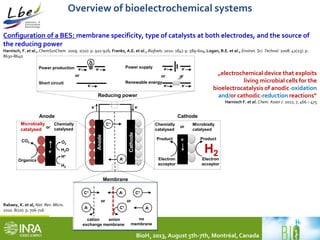
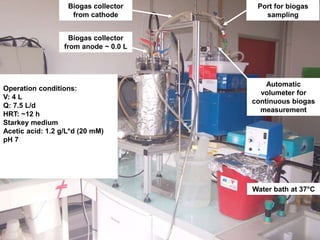
![Continuous high yield hydrogen gas production coupling system:
Dark fermenter → Microbial electrolysis cell
H2 H2
Dark
fermentation
Microbial
electrolysis
Any substrate Organic acids
(acetate,…)
BioH2 2013, August 5th-7th, Montréal, Canada
Outlet
Saline media
pH [7-8]](https://image.slidesharecdn.com/id-2318471-carmonatrablyfinal-141016120020-conversion-gate02/85/BioH2Conference-Alessandro-Carmona-2-320.jpg)


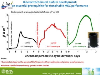
![MEC performances in comparison to other MEC studies
BioH2 2013, August 5th-7th, Montréal, Canada
Eapp./
V
Anode
material
T/
C
VMEC/
L
IA/
A m-2
Iv/
A m-3
Q/
L d-1
CE/ % YH2/
mol mol-1
QH2 /
m3 m-3 d-1
H2/
%
HRT/
h
Ref.
+0.2 Graphite
felt
37 4.00 2-3 400 7.5 22 2.28 0.15 ~90 12 This
work
-0.2 Graphite
brush
30 0.03 0.02 147 0.03 81 N.F. 3.6 68 24 [1]
+0.9 Graphite
brush
30 2.50 1.18 74 2.5 ˃100 N.F. 0.53 70 24 [2]
+0.8 Graphite
felt
28 0.20 2.91 40 N.F. 52 2.1 0.05 96.6 N.F. [3]
+1.5 Graphite
fiber
32 0.13 N.F. 1630 0.46 ˃100 2.0 4.3 53 6.5 [4]
+1.0 Graphite
felt
30 0.28 16.4 732 7.2 60 N.F. 5.6 N.F. 48 [5]
+1.2 Graphite
felt
30 0.05 6.00 0.6 0.008 N.F. 3.36 5.4 N.F. 6 [6]
[1] Nam et al. 2011, [2] Rader et al. 2010, [3] Chae et al. 2008, [4] Lee et al. 2010, [5] Sleutels et al., 2009, [6] Hrapovic et al., 2010
Notes:
•All values are well in line with previous literature data
•However, just a very few studies have reported the coupling of dark fermentation and MEC technology
•So far, theMEC using acetate as a model metabolite shows a stable performance
•Not enough available information onMECs under saline conditions](https://image.slidesharecdn.com/id-2318471-carmonatrablyfinal-141016120020-conversion-gate02/85/BioH2Conference-Alessandro-Carmona-18-320.jpg)


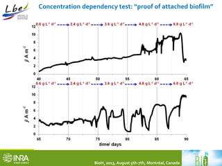
This document summarizes a study coupling a microbial electrolysis cell (MEC) to a dark fermentation reactor for continuous hydrogen production. A saline dark fermenter converted glucose into organic acids like acetate. The MEC was fed these metabolites and produced hydrogen gas at over 90% purity with a conversion rate of 2.28 moles of hydrogen per mole of acetate. Overall, the coupled system achieved 0.48 moles of hydrogen per mole of glucose initially fed to the dark fermenter and maintained stable performance over several weeks of continuous operation under saline conditions.


![Lead Uptacke [Pb(ii)-acetate]](https://cdn.slidesharecdn.com/ss_thumbnails/pbii-acetate-191214144205-thumbnail.jpg?width=640&height=640&fit=bounds)


