Download to read offline

![©2002 Fairchild Semiconductor Corporation Rev. A2, August 2002
BC546/547/548/549/550
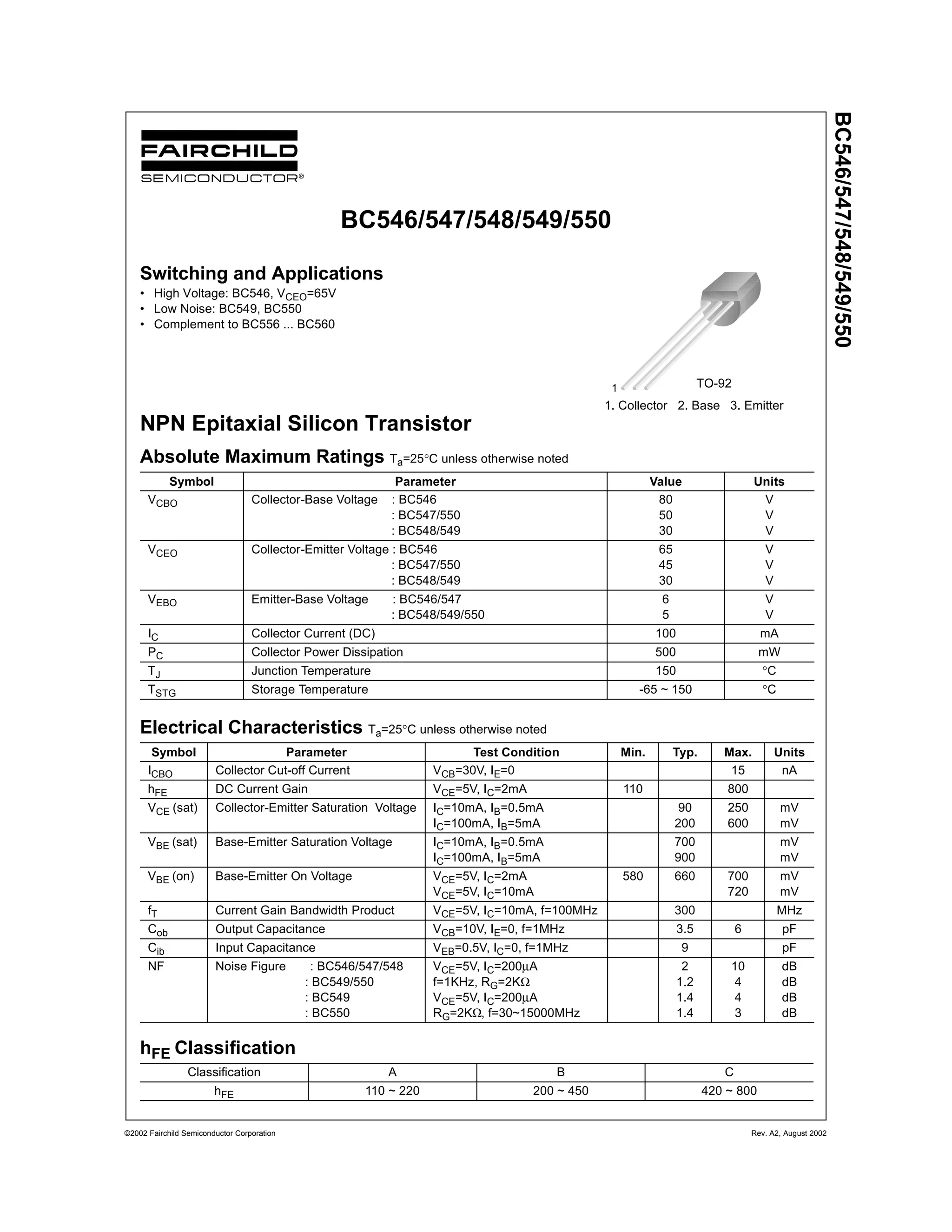
Typical Characteristics
Figure 1. Static Characteristic Figure 2. Transfer Characteristic
Figure 3. DC current Gain Figure 4. Base-Emitter Saturation Voltage
Collector-Emitter Saturation Voltage
Figure 5. Output Capacitance Figure 6. Current Gain Bandwidth Product
0 2 4 6 8 10 12 14 16 18 20
0
20
40
60
80
100
IB
= 50µA
IB
= 100µA
IB
= 150µA
IB
= 200µA
IB
= 250µA
IB
= 300µA
IB
= 350µA
IB
= 400µA
IC
[mA],COLLECTORCURRENT
VCE
[V], COLLECTOR-EMITTER VOLTAGE
0.0 0.2 0.4 0.6 0.8 1.0 1.2
0.1
1
10
100
VCE = 5V
IC[mA],COLLECTORCURRENT
VBE[V], BASE-EMITTER VOLTAGE
1 10 100 1000
1
10
100
1000
VCE = 5V
hFE,DCCURRENTGAIN
IC[mA], COLLECTOR CURRENT
1 10 100 1000
10
100
1000
10000
IC = 10 IB
VCE(sat)
VBE(sat)
VBE(sat),VCE(sat)[mV],SATURATIONVOLTAGE
IC[A], COLLECTOR CURRENT
1 10 100 1000
0.1
1
10
100
f=1MHz
IE = 0
Cob[pF],CAPACITANCE
VCB[V], COLLECTOR-BASE VOLTAGE
0.1 1 10 100
1
10
100
1000
VCE = 5V
fT,CURRENTGAIN-BANDWIDTHPRODUCT
IC[mA], COLLECTOR CURRENT](https://image.slidesharecdn.com/bc547-140522172638-phpapp02/85/Bc547-2-320.jpg)
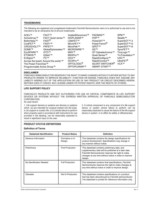
![Package Dimensions
BC546/547/548/549/550
0.46 ±0.10
1.27TYP
(R2.29)
3.86MAX
[1.27 ±0.20]
1.27TYP
[1.27 ±0.20]
3.60 ±0.20
14.47±0.40
1.02±0.10
(0.25)4.58±0.20
4.58
+0.25
–0.15
0.38
+0.10
–0.05
0.38
+0.10
–0.05
TO-92
Dimensions in Millimeters
©2002 Fairchild Semiconductor Corporation Rev. A2, August 2002](https://image.slidesharecdn.com/bc547-140522172638-phpapp02/85/Bc547-3-320.jpg)


This document provides specifications for the BC546/547/548/549/550 NPN epitaxial silicon transistor made by Fairchild Semiconductor. It includes maximum ratings, electrical characteristics at 25°C, hFE classifications, switching and applications information, typical characteristics graphs, and package dimensions. The transistors can handle collector currents up to 100mA, collector-emitter voltages up to 65V, and junction temperatures up to 150°C. They feature current gains from 110 to 800, saturation voltages from 90-250mV, and current gain bandwidths up to 300MHz. The BC549 and BC550 models have particularly low noise figures.


