Download to read offline
![©2000 Fairchild Semiconductor International
BD135/137/139
Rev. A, February 2000
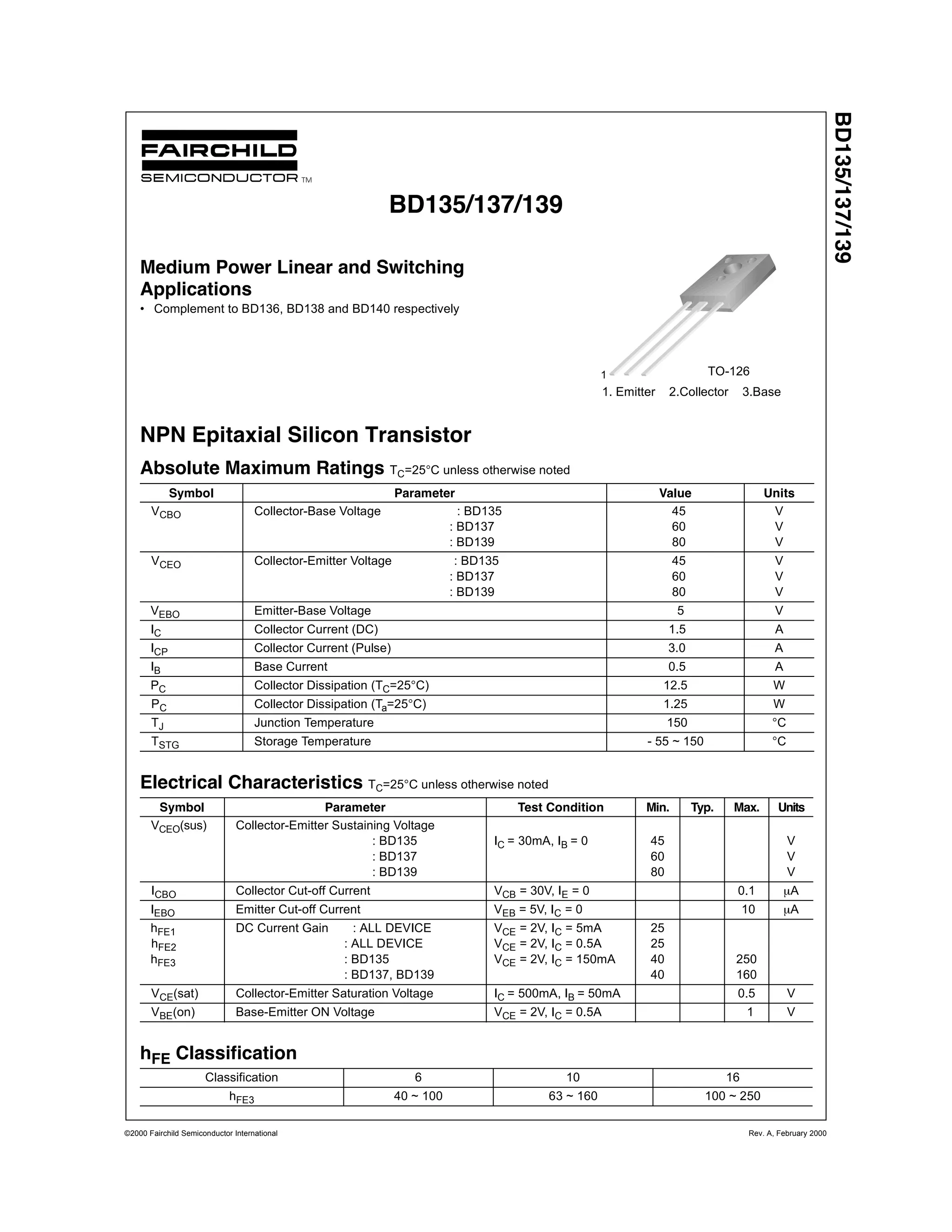
Typical Characteristics
Figure 1. DC current Gain Figure 2. Collector-Emitter Saturation Voltage
Figure 3. Base-Emitter Voltage Figure 4. Safe Operating Area
Figure 5. Power Derating
10 100 1000
0
10
20
30
40
50
60
70
80
90
100
VCE = 2V
hFE,DCCURRENTGAIN
IC[mA], COLLECTOR CURRENT
1E-3 0.01 0.1 1 10
0
50
100
150
200
250
300
350
400
450
500
IC=10IB
IC=20IB
VCE(sat)[mV],SATURATIONVOLTAGE
IC[A], COLLECTOR CURRENT
1E-3 0.01 0.1 1 10
0.1
0.2
0.3
0.4
0.5
0.6
0.7
0.8
0.9
1.0
1.1
VBE(on)
VCE
= 5V
VBE(sat)
IC
= 10 IB
VBE[V],BASE-EMITTERVOLTAGE
IC[A], COLLECTOR CURRENT
1 10 100
0.01
0.1
1
10
BD139
BD137
BD135
10us
100us
1ms
DC
IC MAX. (Pulsed)
IC MAX. (Continuous)
IC[A],COLLECTORCURRENT
VCE[V], COLLECTOR-EMITTER VOLTAGE
0 25 50 75 100 125 150 175
0.0
2.5
5.0
7.5
10.0
12.5
15.0
17.5
20.0
PC[W],POWERDISSIPATION
TC[
o
C], CASE TEMPERATURE](https://image.slidesharecdn.com/bd137datasheet-140522172639-phpapp02/75/Bd137-datasheet-2-2048.jpg)
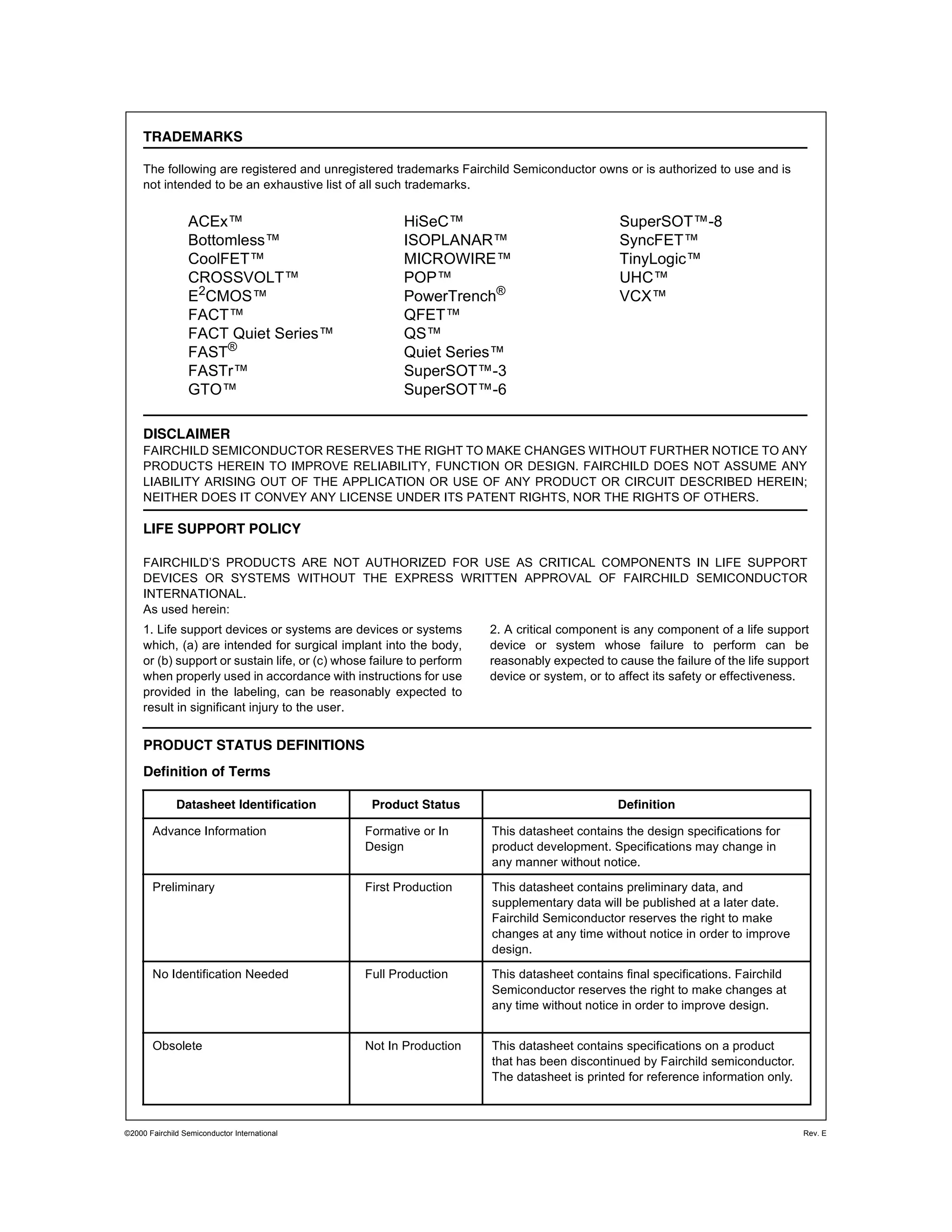
![Package Demensions
©2000 Fairchild Semiconductor International Rev. A, February 2000
BD135/137/139
Dimensions in Millimeters
3.25 ±0.208.00 ±0.30
ø3.20 ±0.10
0.75 ±0.10
#1
0.75 ±0.10
2.28TYP
[2.28±0.20]
2.28TYP
[2.28±0.20]
1.60 ±0.10
11.00±0.20
3.90±0.10
14.20MAX
16.10±0.20
13.06±0.30
1.75 ±0.20
(0.50)(1.00)
0.50
+0.10
–0.05
TO-126](https://image.slidesharecdn.com/bd137datasheet-140522172639-phpapp02/75/Bd137-datasheet-3-2048.jpg)


This document provides specifications for the BD135/137/139 NPN epitaxial silicon transistor series made by Fairchild Semiconductor. It includes maximum ratings, electrical characteristics, typical performance curves, and package dimensions. The transistors are medium power switching devices suitable for linear and switching applications as replacements for similar transistor types. Specifications include current gain, saturation voltage, safe operating area, and power derating curves.


