This document discusses various topics related to surveying, including:
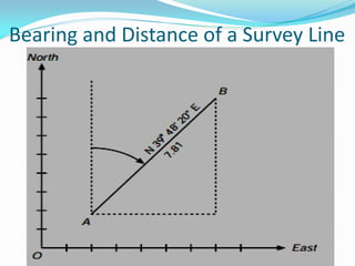
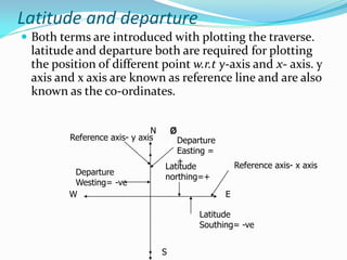
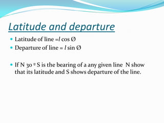
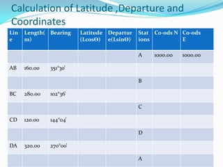
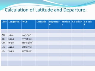
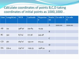
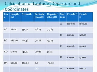
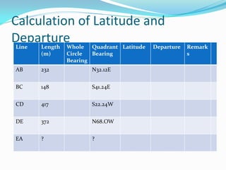
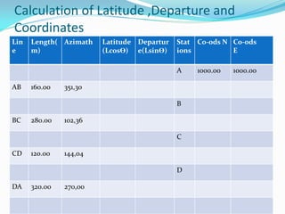
- Latitude and departure are used to plot positions with respect to x- and y-axes, and are calculated from the line length and bearing.
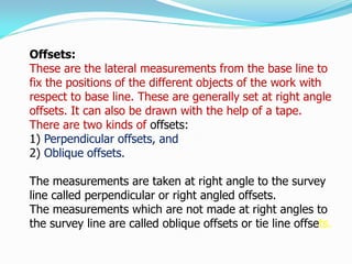
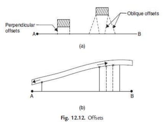
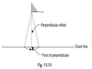
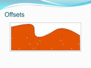
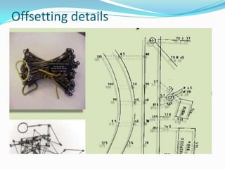
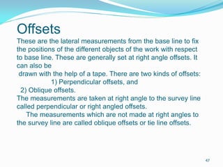
- Offsets are lateral measurements from the base line to fix positions of objects, and can be perpendicular or oblique.
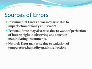
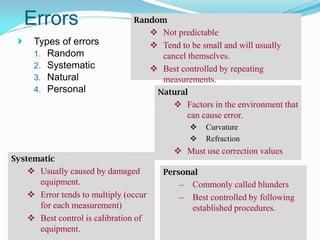
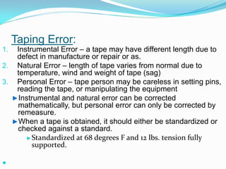
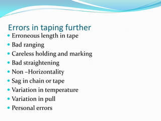
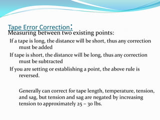
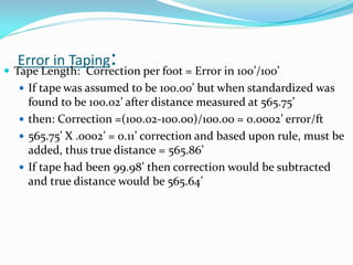
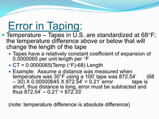
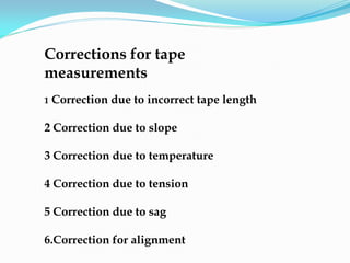
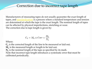
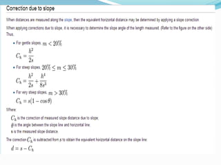
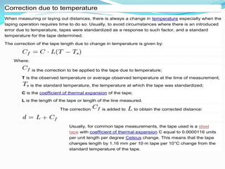
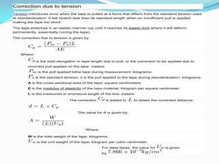
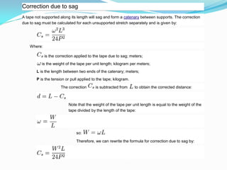
- Errors in surveying can be random, systematic, natural, or personal, and various corrections must be applied for factors like tape length, temperature, tension, and sag.
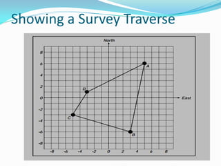
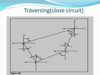
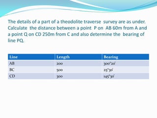
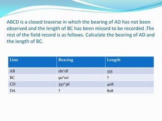
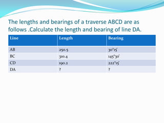
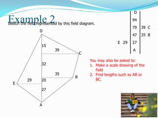
- Calculations are provided for latitude, departure, coordinates, and traversing closed circuits while solving for missing information.


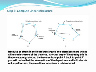
![Step 5: Compute Linear Misclosure (continued)
Linear misclosure = [(departure misclosure)2 + (latitude misclosure)2]1/2](https://image.slidesharecdn.com/lecture3-4part2-220906144059-6d286275/85/Lecture-3-4-part-2-pdf-53-320.jpg)