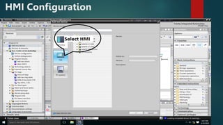
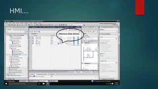
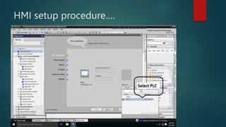
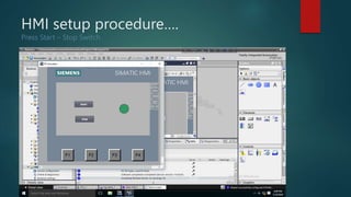
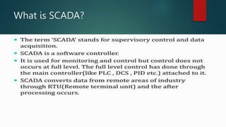
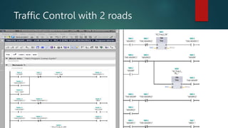
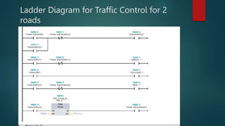
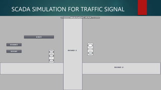
Programmable Logic
Controller
MADE BY: ASIF ADNAN RASHID
What is PLC(Programmable Logic
Controller)
 PLC may be defined as micro-controller based controlling device that used to
store instructions in programmable memory to implement logic, sequencing,
timing, counting and arithmetic function through digital/analog input/output
modules for controlling device or process.
 Why PLC is used over microcontroller?:
I. PLC has more input/output than microcontroller. We can also extend input and
output module in PLC.
II. PLC processing capacity is lot more higher and faster than microcontroller.
III. We can change PLC module or restore data if it is problematic.
IV. PLC can work on high voltage but microcontroller faces some discrepancies
while operating in high voltage.
V. PLC has display unit and observe the current condition, but in microcontroller
we can use display as an add-in service.
Components of PLC
PLC consists of the following units: 1)Processor 2)I/O unit 3)Memory unit 4)Power Supply
5)Programming Unit
PLC Operating Cycle
 PLC automate a process by
I. Read Input
II. Program Scan
III. Energize the Output
IV. Continue the cycle
PLC can be divided into 3 parts:
I. CPU
II. Input/Output
III. Programming Device
When box reaches at the end of the conveyor,
sensor send a signal to PLC to stop the motor as
well as stop the conveyor.
PLC INPUT and OUTPUT Module
Signal of Input and Output Module
SIEMENS PLC
SIEMENS S7-1212C DC/DC/DC
Specifications
SIEMENS S7-1212C DC/DC/DC
Specifications
Family of S7-1200
Schematic Diagram
Addressing System
Peripheral devices of PLC
Input Devices:
1. Limit Switches
2. Proximity Sensors
3. Sensors
4. Relay
5. Solenoid
6. Photoelectric sensors
Output Devices:
1. Actuators
2. Lamps
3. Valves
4. Motors etc
Different Brand PLC
PLC Programming Language
International Standards for PLC specifies Three graphical and Two text-based languages for
programming PLC.
Language Abbreviation Type Application best
suited for
Ladder Logic Diagram LD Graphical Discrete Control
Function Block Diagram FBD Graphical Continuous Control
Sequential Function Chart SFC Graphical Sequencing
Instruction List IL Textural Similar to Ladder Logic
Structured Text ST Textural Complex Logic ,
Computational etc
Ladder Diagram Example
Motor Connection
Motor that is run by PLC is controlled in 2 ways. 1)Power Ckt (AC current) 2) Control Ckt (PLC
)
PLC Ladder Diagram
To On/Off a motor it should follow the undermentioned ladder diagram with latching:
HMI(Human Machine Interface)
HMI Function
HMI setup procedure
 Steps
-Browse PLC
-Continue up to finish(Untick select item)
-Take start, stop, load
-Set properties of elements, object
-Match with PLC tag table
-Simulation
-Download HMI
HMI Configuration
HMI….
Add memory block in program main block
HMI….
HMI setup procedure….
Press Start – Stop Switch
HMI Download
Press Right Button On HMI
Download Hardware and Software
Finish and check HMI screen
What is SCADA?
Advantages
Traffic Control with 2 roads
Ladder Diagram for Traffic Control for 2
roads
SCADA SIMULATION FOR TRAFFIC SIGNAL
THANK YOU FOR YOUR ATTENTION

Basic overview of Programmable Logic Controller(PLC),HMI,SCADA