Downloaded 487 times


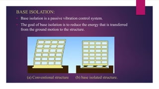

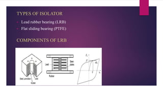
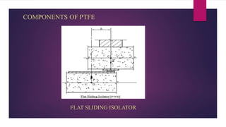
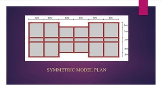

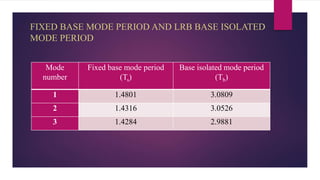
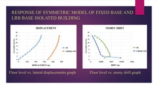
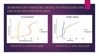
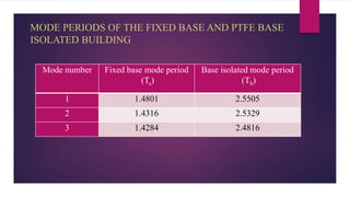
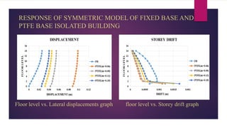
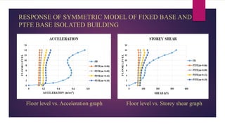
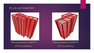
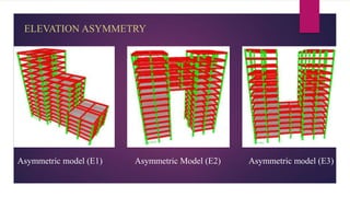
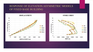
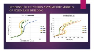
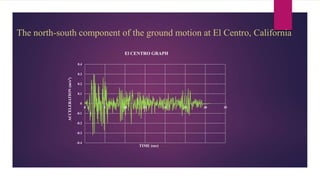
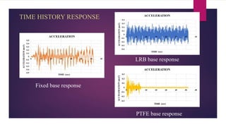
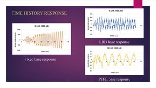
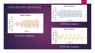
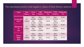
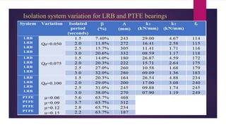
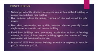
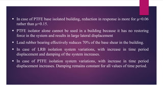

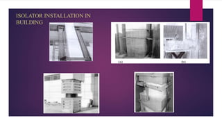


The document discusses the dynamic response of a 14-storey reinforced concrete frame building using base isolators. It aims to analyze the response of the building with and without base isolators, including lead rubber bearings and sliding bearings, under earthquake ground motions. The analysis is performed using the finite element software ETABS. The results show that base isolation is effective at reducing seismic responses like displacement, acceleration, base shear and storey drift compared to a fixed base building. PTFE isolators provide more reduction than LRB isolators in most responses. Irregularities in building plan and elevation also increase the response of a fixed base building.


![Base isolation.ppt [Autosaved] [Autosaved]](https://cdn.slidesharecdn.com/ss_thumbnails/911148fc-85fb-4bf2-b5cd-3b07746ce193-150917033137-lva1-app6891-thumbnail.jpg?width=640&height=640&fit=bounds)


