The Microcontroller Abstraction Layer contains drivers that provide an abstraction of the underlying microcontroller hardware. It aims to make the layers above it independent of the specific microcontroller by presenting a standardized interface.
- AUTOSAR Confidential-
Document ID 053 : AUTOSAR_EXP_LayeredSoftwareArchitecture
2
Document Title Layered Software Architecture
Document Owner AUTOSAR
Document Responsibility AUTOSAR
Document Identification No 053
Document Status Final
Part of AUTOSAR Standard Classic Platform
Part of Standard Release 4.3.1
3.
- AUTOSAR Confidential-
Document ID 053 : AUTOSAR_EXP_LayeredSoftwareArchitecture
3
Document Change History
Date Release Changed by Change Description
2017-12-08 4.3.1 AUTOSAR
Release
Management
Editorial changes
2016-11-30 4.3.0 AUTOSAR
Release
Management
Incorporated new 4.3 concepts for Crypto Stack, Vehicle-2-X Communication, SOME/IP
Transport Protocol, DLT rework
Removed obsolete Dbg module
Editorial changes
2015-07-31 4.2.2 AUTOSAR
Release
Management
Editorial changes
2014-10-31 4.2.1 AUTOSAR
Release
Management
Incorporated new 4.2 concepts for: Switch Configuration; Sender-Receiver-Serialization;
CAN-FD; Large-Data-COM; E2E-Extension; Global Time Synchronization; Support for Post-
build ECU-Configuration; Secure-Onboard-Communication; ASIL/QM-Protection
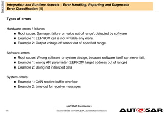
Introduction of new error classification
Editorial changes
2014-03-31 4.1.3 AUTOSAR
Release
Management
Editorial changes
4.
- AUTOSAR Confidential-
Document ID 053 : AUTOSAR_EXP_LayeredSoftwareArchitecture
4
Document Change History
Date Releas
e
Changed by Change Description
2013-03-15 4.1.1 AUTOSAR
Administration
Clarification of partial network support for CAN/LIN slave.
New Ethernet stack extensions
Added Crypto Service Manager to System Services
Revised presentation of J1939 and added new J1939 modules
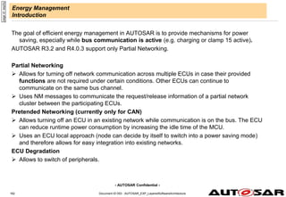
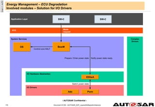
Added new energy management concepts: “Pretended Networking”, “ECU Degradation”
Added new modules: “Output Compare Unit Driver” and “Time Service”
Changed handling of Production Errors
Fixed various typography and layout issues
2011-12-22 4.0.3 AUTOSAR
Administration
Added a note for the R3-compatibility FlexRay Transport Layer FrArTp on slide "ki890".
Added an overview chapter for energy management and partial networking
Corrected examples regarding DEM symbol generation
Fixed minor typography issues
Clarification of term AUTOSAR-ECU on slide "94jt1"
Corrected CDD access description for EcuM on slide "11123“
2009-12-18 4.0.1 AUTOSAR
Administration
Added a note regarding support for System Basis Chips on slide "94juq“
Clarification of DBG and DLT text on slide "3edfg"
Corrected DBG description on slide "11231"
2010-02-02 3.1.4 AUTOSAR
Administration
The document has been newly structured. There are now 3 main parts:
Architecture
Configuration
Integration and Runtime Aspects
The whole content has been updated to reflect the content of the R 4.0 specifications.
Topics which have bee newly introduced or heavily extended in release 4.0 have been
added. E.g.,. Multi-Core Systems, Partitioning, Mode Management, Error Handling,
Reporting and Diagnostic, Debugging, Measurement and Calibration, Functional Safety etc
Legal disclaimer revised
5.
- AUTOSAR Confidential-
Document ID 053 : AUTOSAR_EXP_LayeredSoftwareArchitecture
5
Document Change History
Date Release Changed by Change Description
2008-08-13 3.1.1 AUTOSAR
Administration
Legal disclaimer revised
2007-12-21 3.0.1 AUTOSAR
Administration
Updates based on new wakeup/startup concepts
Detailed explanation for post-build time configuration
"Slimming" of LIN stack description
ICC2 figure
Document meta information extended
Small layout adaptations made
2007-01-24 2.1.15 AUTOSAR
Administration
ICC clustering added.
Document contents harmonized
Legal disclaimer revised
Release Notes added
“Advice for users” revised
“Revision Information” added
2006-11-28 2.1.1 AUTOSAR
Administration
Rework Of:
Error Handling
Scheduling Mechanisms
More updates according to architectural decisions in R2.0
2006-01-02 1.0.1 AUTOSAR
Administration
Correct version released
2005-05-31 1.0.0 AUTOSAR
Administration
Initial release
6.
- AUTOSAR Confidential-
Document ID 053 : AUTOSAR_EXP_LayeredSoftwareArchitecture
6
Disclaimer
Disclaimer
This work (specification and/or software implementation) and the material contained in it, as released by AUTOSAR, is for the purpose
of information only. AUTOSAR and the companies that have contributed to it shall not be liable for any use of the work.
The material contained in this work is protected by copyright and other types of intellectual property rights. The commercial exploitation
of the material contained in this work requires a license to such intellectual property rights.
This work may be utilized or reproduced without any modification, in any form or by any means, for informational purposes only. For any
other purpose, no part of the work may be utilized or reproduced, in any form or by any means, without permission in writing from the
publisher.
The work has been developed for automotive applications only. It has neither been developed, nor tested for non-automotive
applications.
The word AUTOSAR and the AUTOSAR logo are registered trademarks.
7.
- AUTOSAR Confidential-
Table of contents
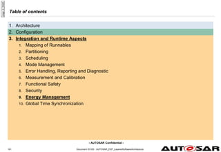
1. Architecture
1. Overview of Software Layers
2. Content of Software Layers
3. Content of Software Layers in Multi-Core Systems
4. Content of Software Layers in Mixed-Critical Systems
5. Overview of Modules
6. Interfaces
1. General
2. Interaction of Layers (Examples)
2. Configuration
3. Integration and Runtime Aspects
Document ID 053 : AUTOSAR_EXP_LayeredSoftwareArchitecture
17
page
id:
94jt4
8.
- AUTOSAR Confidential-
Document ID 053 : AUTOSAR_EXP_LayeredSoftwareArchitecture
18
Introduction
Purpose and Inputs
Purpose of this document
The Layered Software Architecture describes the software architecture of AUTOSAR:
it describes in an top-down approach the hierarchical structure of AUTOSAR software and
maps the Basic Software Modules to software layers and
shows their relationship.
This document does not contain requirements and is informative only. The examples given are
not meant to be complete in all respects.
This document focuses on static views of a conceptual layered software architecture:
it does not specify a structural software architecture (design) with detailed static and dynamic
interface descriptions,
these information are included in the specifications of the basic software modules
themselves.
Inputs
This document is based on specification and requirement documents of AUTOSAR.
page
id:
94jt2
9.
- AUTOSAR Confidential-
Document ID 053 : AUTOSAR_EXP_LayeredSoftwareArchitecture
19
Introduction
Scope and Extensibility
Application scope of AUTOSAR
AUTOSAR is dedicated for Automotive ECUs. Such ECUs have the following properties:
strong interaction with hardware (sensors and actuators),
connection to vehicle networks like CAN, LIN, FlexRay or Ethernet,
microcontrollers (typically 16 or 32 bit) with limited resources of computing power and memory (compared
with enterprise solutions),
Real Time System and
program execution from internal or external flash memory.
NOTE: In the AUTOSAR sense an ECU means one microcontroller plus peripherals and the according
software/configuration. The mechanical design is not in the scope of AUTOSAR. This means that if more than
one microcontroller in arranged in a housing, then each microcontroller requires its own description of an
AUTOSAR-ECU instance.
AUTOSAR extensibility
The AUTOSAR Software Architecture is a generic approach:
standard modules can be extended in functionality, while still being compliant,
still, their configuration has to be considered in the automatic Basic SW configuration process!
non-standard modules can be integrated into AUTOSAR-based systems as Complex Drivers and
further layers cannot be added.
page
id:
94jt1
10.
- AUTOSAR Confidential-
Document ID 053 : AUTOSAR_EXP_LayeredSoftwareArchitecture
20
Architecture – Overview of Software Layers
Top view
Microcontroller
Application Layer
Runtime Environment (RTE)
page
id:
94qu9
Basic Software (BSW)
The AUTOSAR Architecture distinguishes on the highest abstraction level between three
software layers: Application, Runtime Environment and Basic Software which run on a
Microcontroller.
11.
- AUTOSAR Confidential-
Document ID 053 : AUTOSAR_EXP_LayeredSoftwareArchitecture
21
Architecture – Overview of Software Layers
Coarse view
Complex
Drivers
Microcontroller
Microcontroller Abstraction Layer
Services Layer
Application Layer
Runtime Environment
ECU Abstraction Layer
page
id:
94ju3
The AUTOSAR Basic Software is further divided in the layers: Services, ECU Abstraction,
Microcontroller Abstraction and Complex Drivers.
12.
- AUTOSAR Confidential-
Document ID 053 : AUTOSAR_EXP_LayeredSoftwareArchitecture
22
Architecture – Overview of Software Layers
Detailed view
Complex
Drivers
Microcontroller
Runtime Environment
Microcontroller
Drivers
Memory
Drivers
I/O Drivers
I/O Hardware
Abstraction
Memory
Hardware
Abstraction
Memory
Services
System Services
Onboard
Device
Abstraction
Wireless
Communication
Drivers
Communication
Hardware
Abstraction
Off-board
Communication
Services
Application Layer
page
id:
94ju4
The Basic Software Layers are further divided into functional groups. Examples of Services
are System, Memory and Communication Services.
Crypto Drivers
Crypto
Hardware
Abstraction
Crypto
Services
Communication
Drivers
Communication
Services
Wireless
Communication
HW Abstraction
13.
- AUTOSAR Confidential-
Document ID 053 : AUTOSAR_EXP_LayeredSoftwareArchitecture
23
Architecture – Overview of Software Layers
Microcontroller Abstraction Layer
The Microcontroller Abstraction Layer is the
lowest software layer of the Basic Software.
It contains internal drivers, which are software
modules with direct access to the µC and
internal peripherals.
Task
Make higher software layers independent of µC
Properties
Implementation: µC dependent
Upper Interface: standardized and µC
independent
Co
mpl
ex
Driv
ers
Microcontroller
Microcontroller Abstraction Layer
Application Layer
RTE
ECU Abstraction Layer
page
id:
94ju6
14.
- AUTOSAR Confidential-
Document ID 053 : AUTOSAR_EXP_LayeredSoftwareArchitecture
24
Architecture – Overview of Software Layers
ECU Abstraction Layer
The ECU Abstraction Layer interfaces the
drivers of the Microcontroller Abstraction
Layer. It also contains drivers for external
devices.
It offers an API for access to peripherals and
devices regardless of their location (µC
internal/external) and their connection to the
µC (port pins, type of interface)
Task
Make higher software layers independent of
ECU hardware layout
Properties
Implementation: µC independent, ECU hardware
dependent
Upper Interface: µC and ECU hardware
independent
Co
mpl
ex
Driv
ers
Microcontroller
Microcontroller Abstraction Layer
Application Layer
RTE
ECU Abstraction Layer
ECU Abstraction Layer
page
id:
94ju7
15.
- AUTOSAR Confidential-
Document ID 053 : AUTOSAR_EXP_LayeredSoftwareArchitecture
25
Architecture – Overview of Software Layers
Complex Drivers
The Complex Drivers Layer spans from the
hardware to the RTE.
Task
Provide the possibility to integrate special purpose
functionality, e.g. drivers for devices:
which are not specified within AUTOSAR,
with very high timing constrains or
for migration purposes etc.
Properties
Implementation: might be application, µC and ECU
hardware dependent
Upper Interface: might be application, µC and ECU
hardware dependent
Microcontroller
Microcontroller Abstraction Layer
Application Layer
RTE
ECU Abstraction Layer
Services Layer
ECU Abstraction Layer
page
id:
94jwe
Complex
Drivers
16.
- AUTOSAR Confidential-
Document ID 053 : AUTOSAR_EXP_LayeredSoftwareArchitecture
26
Architecture – Overview of Software Layers
Services Layer
The Services Layer is the highest layer of the Basic
Software which also applies for its relevance for
the application software: while access to I/O
signals is covered by the ECU Abstraction Layer,
the Services Layer offers:
Operating system functionality
Vehicle network communication and management
services
Memory services (NVRAM management)
Diagnostic Services (including UDS communication, error
memory and fault treatment)
ECU state management, mode management
Logical and temporal program flow monitoring (Wdg
manager)
Task
Provide basic services for applications, RTE and
basic software modules.
Properties
Implementation: mostly µC and ECU hardware
independent
Upper Interface: µC and ECU hardware independent
Complex
Drivers
Microcontroller
Microcontroller Abstraction Layer
Application Layer
RTE
ECU Abstraction Layer
Services Layer
ECU Abstraction Layer
page
id:
94ju8
17.
- AUTOSAR Confidential-
Document ID 053 : AUTOSAR_EXP_LayeredSoftwareArchitecture
27
Architecture – Overview of Software Layers
AUTOSAR Runtime Environment (RTE)
The RTE is a layer providing communication services
to the application software (AUTOSAR Software
Components and/or AUTOSAR Sensor/Actuator
components).
Above the RTE the software architecture style
changes from “layered“ to “component style“.
The AUTOSAR Software Components communicate
with other components (inter and/or intra ECU)
and/or services via the RTE.
Task
Make AUTOSAR Software Components independent
from the mapping to a specific ECU.
Properties
Implementation: ECU and application specific
(generated individually for each ECU)
Upper Interface: completely ECU independent
Microcontroller
Microcontroller Abstraction Layer
Application Layer
AUTOSAR Runtime Environment (RTE)
ECU Abstraction Layer
Services Layer
ECU Abstraction Layer
page
id:
94ju9
Complex
Drivers
18.
- AUTOSAR Confidential-
Document ID 053 : AUTOSAR_EXP_LayeredSoftwareArchitecture
28
Architecture – Overview of Software Layers
Introduction to types of services
The Basic Software can be subdivided into the following types of services:
Input/Output (I/O)
Standardized access to sensors, actuators and ECU onboard peripherals
Memory
Standardized access to internal/external memory (non volatile memory)
Crypto
Standardized access to cryptographic primitives including internal/external hardware
accelerators
Communication
Standardized access to: vehicle network systems, ECU onboard communication systems and
ECU internal SW
Off-board Communication
Standardized access to: Vehicle-to-X communication, in vehicle wireless network systems,
ECU off-board communication systems
System
Provision of standardizeable (operating system, timers, error memory) and ECU specific (ECU
state management, watchdog manager) services and library functions
page
id:
94j33
19.
- AUTOSAR Confidential-
Document ID 053 : AUTOSAR_EXP_LayeredSoftwareArchitecture
29
Architecture – Introduction to Basic Software Module Types
Driver (internal)
A driver contains the functionality to control and access an internal or an external device.
Internal devices are located inside the microcontroller. Examples for internal devices are:
Internal EEPROM
Internal CAN controller
Internal ADC
A driver for an internal device is called internal driver and is located in the Microcontroller
Abstraction Layer.
page
id:
94jui
20.
- AUTOSAR Confidential-
Document ID 053 : AUTOSAR_EXP_LayeredSoftwareArchitecture
30
Architecture – Introduction to Basic Software Module Types
Driver (external)
External devices are located on the ECU hardware outside the microcontroller. Examples for
external devices are:
External EEPROM
External watchdog
External flash
A driver for an external device is called external driver and is located in the ECU Abstraction
Layer. It accesses the external device via drivers of the Microcontroller Abstraction Layer.
This way also components integrated in System Basis Chips (SBCs) like transceivers and
watchdogs are supported by AUTOSAR.
Example: a driver for an external EEPROM with SPI interface accesses the external
EEPROM via the handler/driver for the SPI bus.
Exception:
The drivers for memory mapped external devices (e.g. external flash memory) may access the
microcontroller directly. Those external drivers are located in the Microcontroller Abstraction
Layer because they are microcontroller dependent.
page
id:
94juq
21.
- AUTOSAR Confidential-
Document ID 053 : AUTOSAR_EXP_LayeredSoftwareArchitecture
31
Architecture – Introduction to Basic Software Module Types
Interface
An Interface (interface module) contains the functionality to abstract from modules which are
architecturally placed below them. E.g., an interface module which abstracts from the
hardware realization of a specific device. It provides a generic API to access a specific type of
device independent on the number of existing devices of that type and independent on the
hardware realization of the different devices.
The interface does not change the content of the data.
In general, interfaces are located in the ECU Abstraction Layer.
Example: an interface for a CAN communication system provides a generic API to access CAN
communication networks independent on the number of CAN Controllers within an ECU and
independent of the hardware realization (on chip, off chip).
page
id:
94jwx
22.
- AUTOSAR Confidential-
Document ID 053 : AUTOSAR_EXP_LayeredSoftwareArchitecture
32
Architecture – Introduction to Basic Software Module Types
Handler
A handler is a specific interface which controls the concurrent, multiple and asynchronous
access of one or multiple clients to one or more drivers. I.e. it performs buffering, queuing,
arbitration, multiplexing.
The handler does not change the content of the data.
Handler functionality is often incorporated in the driver or interface (e.g. SPIHandlerDriver, ADC
Driver).
page
id:
94jww
23.
- AUTOSAR Confidential-
Document ID 053 : AUTOSAR_EXP_LayeredSoftwareArchitecture
33
Architecture – Introduction to Basic Software Module Types
Manager
A manager offers specific services for multiple clients. It is needed in all cases where pure
handler functionality is not enough to abstract from multiple clients.
Besides handler functionality, a manager can evaluate and change or adapt the content of the
data.
In general, managers are located in the Services Layer
Example: The NVRAM manager manages the concurrent access to internal and/or external
memory devices like flash and EEPROM memory. It also performs distributed and reliable
data storage, data checking, provision of default values etc.
page
id:
94j22
24.
- AUTOSAR Confidential-
Document ID 053 : AUTOSAR_EXP_LayeredSoftwareArchitecture
34
Architecture – Overview of Software Layers
Introduction to Libraries
Libraries are a collection of functions for
related purposes
Libraries:
can be called by BSW modules (that
including the RTE), SW-Cs, libraries
or integration code
run in the context of the caller in the
same protection environment
can only call libraries
are re-entrant
do not have internal states
do not require any initialization
are synchronous, i.e. they do not have
wait points
page
id:
99j22
AUTOSAR
Libraries
Basic Software
Runtime Environment (RTE)
Application Layer
ECU Hardware
The following libraries are
specified within AUTOSAR:
Fixed point mathematical,
Floating point mathematical,
Interpolation for fixed point data,
Interpolation for floating point data,
Bit handling,
E2E communication,
CRC calculation,
Extended functions (e.g. 64bits
calculation, filtering, etc.)
25.
- AUTOSAR Confidential-
Table of contents
1. Architecture
1. Overview of Software Layers
2. Content of Software Layers
3. Content of Software Layers in Multi-Core Systems
4. Content of Software Layers in Mixed-Critical Systems
5. Overview of Modules
6. Interfaces
1. General
2. Interaction of Layers (Examples)
2. Configuration
3. Integration and Runtime Aspects
Document ID 053 : AUTOSAR_EXP_LayeredSoftwareArchitecture
35
page
id:
94jt4
26.
- AUTOSAR Confidential-
Document ID 053 : AUTOSAR_EXP_LayeredSoftwareArchitecture
36
Architecture – Content of Software Layers
Microcontroller Abstraction Layer
The µC Abstraction Layer consists of the following module groups:
Microcontroller Drivers
Drivers for internal peripherals (e.g. Watchdog, General Purpose Timer)
Functions with direct µC access (e.g. Core test)
Communication Drivers
Drivers for ECU onboard (e.g. SPI) and vehicle communication (e.g. CAN).
OSI-Layer: Part of Data Link Layer
Memory Drivers
Drivers for on-chip memory devices (e.g. internal Flash, internal EEPROM) and memory mapped external memory devices
(e.g. external Flash)
I/O Drivers:
Drivers for analog and digital I/O (e.g. ADC, PWM, DIO)
Crypto Drivers Drivers for on-chip crypto devices like SHE or HSM
Wireless Communication Drivers: Drivers for wireless network systems (in-vehicle or off-board communication)
Microcontroller
ADC
CCU
I/O Drivers
ADC
Driver
DIO
Driver
OCU
Driver
PWM
Driver
ICU
Driver
PWM
LIN
or
SCI
CAN
SPI
EEPROM
FLASH
WDT
GPT
Microcontroller Drivers Communication Drivers
Memory Drivers
RAM
Test
internal
EEPROM
Driver
internal
Flash
Driver
Watchdog
Driver
MCU
Driver
Core
Test
GPT
Driver
Software
module
internal
peripheral
device
Group of
Software
modules of
similar type
MCU
Power
&
Clock
Unit
Microcontroller (µC)
RTE
Application Layer
page
id:
oiu42
CAN
Driver
LIN
Driver
FlexRay
Driver
SPI
Handler
Driver
Ethernet
Driver
Flash
Test
PORT
Driver
DIO
OCU
Wireless
Comm.
Drivers
Crypto
Drivers
Crypto
Driver
Wireless
Ethernet
Driver
SHE/HSM
27.
- AUTOSAR Confidential-
Document ID 053 : AUTOSAR_EXP_LayeredSoftwareArchitecture
37
Architecture – Content of Software Layers
Microcontroller Abstraction Layer: SPIHandlerDriver
The SPIHandlerDriver allows concurrent
access of several clients to one or more SPI
busses.
To abstract all features of a SPI microcontroller
pins dedicated to Chip Select, those shall
directly be handled by the SPIHandlerDriver.
That means those pins shall not be available
in DIO Driver.
Example:
Microcontroller (µC)
Memory
HW Abstr.
RTE
Onboard
Dev. Abstr.
Communi-
cation
Drivers
COM HW
Abstr.
Application Layer
Memory Hardware
Abstraction
I/O Hardware Abstraction
µC SPI
Communication Drivers
SPIHandlerDriver
Driver for ext.
I/O ASIC
Driver for ext.
ADC ASIC
Onboard Device
Abstraction
External
Watchdog Driver
External
EEPROM
Driver
page
id:
swr42
28.
- AUTOSAR Confidential-
Document ID 053 : AUTOSAR_EXP_LayeredSoftwareArchitecture
38
Architecture – Content of Software Layers
Complex Drivers
A Complex Driver is a module which implements non-
standardized functionality within the basic software
stack.
An example is to implement complex sensor
evaluation and actuator control with direct access
to the µC using specific interrupts and/or complex
µC peripherals (like PCP, TPU), e.g.
Injection control
Electric valve control
Incremental position detection
Task:
Fulfill the special functional and timing requirements
for handling complex sensors and actuators
Properties:
Implementation: highly µC, ECU and application
dependent
Upper Interface to SW-Cs: specified and implemented
according to AUTOSAR (AUTOSAR interface)
Lower interface: restricted access to Standardized
Interfaces
Complex Drivers
Electric
Valve
Control
Injection
Control
Incremental
Position
Detection
Complex
Driver
XY
µC
e.g.
CCU
e.g.
PCP
e.g.
TPU
Example:
Complex
Drivers
Microcontroller (µC)
RTE
Application Layer
page
id:
21112
29.
- AUTOSAR Confidential-
Document ID 053 : AUTOSAR_EXP_LayeredSoftwareArchitecture
39
Architecture – Content of Software Layers
ECU Abstraction: I/O Hardware Abstraction
The I/O Hardware Abstraction is a group of modules
which abstracts from the location of peripheral I/O
devices (on-chip or on-board) and the ECU
hardware layout (e.g. µC pin connections and
signal level inversions). The I/O Hardware
Abstraction does not abstract from the
sensors/actuators!
The different I/O devices might be accessed via an I/O
signal interface.
Task:
Represent I/O signals as they are connected to the
ECU hardware (e.g. current, voltage, frequency).
Hide ECU hardware and layout properties from higher
software layers.
Properties:
Implementation: µC independent, ECU hardware
dependent
Upper Interface: µC and ECU hardware independent,
dependent on signal type specified and
implemented according to AUTOSAR (AUTOSAR
interface)
Example:
Microcontroller (µC)
RTE
Communi-
cation
Drivers
I/O
Drivers
I/O HW
Abstraction
Application Layer
COM Drivers
I/O Hardware Abstraction
I/O Signal Interface
Driver for ext.
I/O ASIC
µC
I/O Drivers
DIO
Driver
SPIHandler
Driver
SPI
DIO
Driver for ext.
ADC ASIC
ADC
Driver
ADC
page
id:
ddeaq
30.
- AUTOSAR Confidential-
Document ID 053 : AUTOSAR_EXP_LayeredSoftwareArchitecture
40
Architecture – Content of Software Layers
ECU Abstraction: Communication Hardware Abstraction
The Communication Hardware Abstraction is a
group of modules which abstracts from the
location of communication controllers and the ECU
hardware layout. For all communication systems a
specific Communication Hardware Abstraction is
required (e.g. for LIN, CAN, FlexRay).
Example: An ECU has a microcontroller with 2 internal
CAN channels and an additional on-board ASIC
with 4 CAN controllers. The CAN-ASIC is
connected to the microcontroller via SPI.
The communication drivers are accessed via bus
specific interfaces (e.g. CAN Interface).
Task:
Provide equal mechanisms to access a bus channel
regardless of it‘s location (on-chip / on-board)
Properties:
Implementation: µC independent, ECU hardware
dependent and external device dependent
Upper Interface: bus dependent, µC and ECU
hardware independent
Example:
Microcontroller (µC)
RTE
Communi-
cation
Drivers
COM HW
Abstr.
I/O
Drivers
Application Layer
Communication Hardware Abstraction
Driver for ext.
CAN ASIC
µC
CAN
SPI
Communication Drivers
CAN
Driver
SPIHandler
Driver
I/O Drivers
DIO
Driver
DIO
CAN
Trans-
ceiver
Driver
page
id:
zzttz
CAN Interface
31.
- AUTOSAR Confidential-
Document ID 053 : AUTOSAR_EXP_LayeredSoftwareArchitecture
41
Architecture – Content of Software Layers
Scope: Memory Hardware Abstraction
The Memory Hardware Abstraction is a group of
modules which abstracts from the location of
peripheral memory devices (on-chip or on-board)
and the ECU hardware layout.
Example: on-chip EEPROM and external EEPROM
devices are accessible via the same
mechanism.
The memory drivers are accessed via memory specific
abstraction/emulation modules (e.g. EEPROM
Abstraction).
By emulating an EEPROM abstraction on top of Flash
hardware units a common access via Memory
Abstraction Interface to both types of hardware is
enabled.
Task:
Provide equal mechanisms to access internal (on-chip)
and external (on-board)
memory devices and type of memory hardware
(EEPROM, Flash).
Properties:
Implementation: µC independent, external device
dependent
Upper Interface: µC, ECU hardware and memory
device independent
Example:
Microcontroller (µC)
Memory
Drivers
Memory
HW Abstr.
RTE
Communi-
cation
Drivers
Application Layer
COM Drivers
Memory Hardware Abstraction
µC
Memory Drivers
EEPROM
Driver
SPIHandler
Driver
SPI
EEPROM
Flash
Internal
Flash
Driver
Memory Abstraction Interface
External
EEPROM Driver
page
id:
wwwaa
EEPROM Abstraction
External
Flash Driver
Flash EEPROM
Emulation
32.
- AUTOSAR Confidential-
Document ID 053 : AUTOSAR_EXP_LayeredSoftwareArchitecture
42
Architecture – Content of Software Layers
Onboard Device Abstraction
The Onboard Device Abstraction contains
drivers for ECU onboard devices which
cannot be seen as sensors or actuators like
internal or external watchdogs. Those
drivers access the ECU onboard devices via
the µC Abstraction Layer.
Task:
Abstract from ECU specific onboard devices.
Properties:
Implementation: µC independent, external
device dependent
Upper Interface: µC independent, partly ECU
hardware dependent
Example:
Microcontroller (µC)
Micro-
controller
Drivers
RTE
Onboard
Dev. Abstr.
Communi-
cation
Drivers
Application Layer
COM Drivers
Onboard Device Abstraction
µC
Microcontroller
Drivers
SPIHandler
Driver
SPI
internal
watchdog
driver
Wdg
External
Watchdog Driver
Watchdog Interface
page
id:
xxdxx
33.
- AUTOSAR Confidential-
Document ID 053 : AUTOSAR_EXP_LayeredSoftwareArchitecture
43
Architecture – Content of Software Layers
Scope: Crypto Hardware Abstraction
The Crypto Hardware Abstraction is a group of
modules which abstracts from the location of
cryptographic primitives (internal- or external
hardware or software-based).
Example: AES primitive is realized in SHE or provided
as software library
Task:
Provide equal mechanisms to access internal (on-chip)
and software
cryptographic devices.
Properties:
Implementation: µC independent
Upper Interface: µC, ECU hardware and crypto device
independent
Example:
Crypto Drivers
Crypto Hardware Abstraction
µC
Crypto
Driver
HSM
Crypto Interface
page
id:
wchaa
Crypto
Driver
(SW-based)
SHE
Crypto
Driver
External
Crypto
Driver
Communication Drivers
SPIHandlerDriver
SPI
Microcontroller (µC)
Cryptor
Drivers
Crypto HW
Abstr.
RTE
Crypto
Services
Communi-
cation
Drivers
Application Layer
34.
- AUTOSAR Confidential-
Document ID 053 : AUTOSAR_EXP_LayeredSoftwareArchitecture
44
Architecture – Content of Software Layers
Services: Crypto Services
The Crypto Services consist of one module,
the Crypto Service Manager. It is
responsible for the management of
cryptographic jobs and storage of keys.
Task: Provide cryptographic primitives and key
storage to the application in a uniform way.
Abstract from hardware devices and
properties.
Properties:
Implementation: µC and ECU hardware
independent, highly configurable
Upper Interface: µC and ECU hardware
independent specified and implemented
according to AUTOSAR
(AUTOSAR interface)
Example:
Microcontroller (µC)
Crypto
Drivers
Crypto HW
Abstr.
RTE
Crypto
Services
Application Layer
Crypto Services
Crypto Service Manager
page
id:
9csff
35.
- AUTOSAR Confidential-
Document ID 053 : AUTOSAR_EXP_LayeredSoftwareArchitecture
45
Architecture – Content of Software Layers
Communication Services – General
The Communication Services are a group of
modules for vehicle network communication (CAN,
LIN, FlexRay and Ethernet). They interface with
the communication drivers via the communication
hardware abstraction.
Task:
Provide a uniform interface to the vehicle network for
communication.
Provide uniform services for network management
Provide uniform interface to the vehicle network for
diagnostic communication
Hide protocol and message properties from the
application.
Properties:
Implementation: µC and ECU HW independent, partly
dependent on bus type
Upper Interface: µC, ECU hardware and bus type
independent
The communication services will be detailed for each
relevant vehicle network system on the following
pages.
Example:
Microcontroller (µC)
RTE
Communi-
cation
Services
Application Layer
Communication Services
<Bus specific>
Transport
Protocol
<Bus
specific>
NM
IPDU
Multiplexer
Generic
NM
Interface
<Bus
specific>
State
Manager
page
id:
yyxyy
Bus specific modules
Secure
Onboard
Communication
Diagnostic
Com.
Manager
AUTOSAR
COM
Diagnostic
Log
and
Trace
PDU Router
SOME/IP
Transformer
Com
Based
Transformer
E2E
Transformer
Large
Data
COM
36.
- AUTOSAR Confidential-
Document ID 053 : AUTOSAR_EXP_LayeredSoftwareArchitecture
46
Architecture – Content of Software Layers
Communication Stack – CAN
The CAN Communication Services are a group of
modules for vehicle network communication with the
communication system CAN.
Task:
Provide a uniform interface to the CAN network.
Hide protocol and message properties from the
application.
The CAN Communication Stack supports:
Classic CAN communication (CAN 2.0)
CAN FD communication, if supported by hardware
Example:
Microcontroller (µC)
RTE
Communi-
cation
Drivers
Communi-
cation
Services
COM HW
Abstr.
I/O
Drivers
Application Layer
I/O Drivers
Communication Services
Communication Drivers
Communication Hardware Abstraction
CAN Driver
Driver for ext.
CAN ASIC
SPIHandler
Driver
CAN NM
µC SPI CAN
External
CAN Controller
CAN Transceiver
Driver
DIO Driver
Generic NM
Interface
CAN
State
Manager
page
id:
ppopp
CAN Interface
CAN Transport
Protocol
IPDU
Multiplexer
PDU Router
Secure
Onboard
Communication
Diagnostic
Com.
Manager
AUTOSAR
COM
Diagnostic
Log
and
Trace
Large
Data
COM
37.
- AUTOSAR Confidential-
Document ID 053 : AUTOSAR_EXP_LayeredSoftwareArchitecture
47
Architecture – Content of Software Layers
Communication Stack – CAN
Properties:
Implementation: µC and ECU HW independent, partly
dependent on CAN.
AUTOSAR COM, Generic NM (Network Management)
Interface and Diagnostic Communication Manager are the
same for all vehicle network systems and exist as one
instance per ECU.
Generic NM Interface contains only a dispatcher. No
further functionality is included. In case of gateway ECUs it
can also include the NM coordinator functionality which
allows to synchronize multiple different networks (of the
same or different types) to synchronously wake them up or
shut them down.
CAN NM is specific for CAN networks and will be
instantiated per CAN vehicle network system.
The communication system specific Can State Manager
handles the communication system dependent Start-up
and Shutdown features. Furthermore it controls the
different options of COM to send PDUs and to monitor
signal timeouts.
page
id:
bbnnh
Microcontroller (µC)
RTE
Communi-
cation
Drivers
Communi-
cation
Services
COM HW
Abstr.
I/O
Drivers
Application Layer
38.
- AUTOSAR Confidential-
Document ID 053 : AUTOSAR_EXP_LayeredSoftwareArchitecture
48
Architecture – Content of Software Layers
Communication Stack Extension – TTCAN
The TTCAN Communication Services are the
optional extensions of the plain CAN Interface and
CAN Driver module for vehicle network communi-
cation with the communication system TTCAN.
Task:
Provide a uniform interface to the TTCAN network.
Hide protocol and message properties from the
application.
Please Note:
The CAN Interface with TTCAN can serve both a
plain CAN Driver and a CAN Driver TTCAN.
Example:
I/O Drivers
Communication Services
Communication Drivers
Communication Hardware Abstraction
CAN Driver
Driver for ext.
CAN ASIC
SPIHandler
Driver
CAN NM
µC SPI TTCAN
External
TTCAN Controller
CAN Transceiver
Driver
DIO Driver
Generic NM
Interface
CAN
State
Manager
page
id:
qwwwe
CAN Interface
TTCAN
TTCAN
CAN Transport
Protocol
IPDU
Multiplexer
PDU Router
Secure
Onboard
Communication
Diagnostic
Com.
Manager
AUTOSAR
COM
Diagnostic
Log
and
Trace
Large
Data
COM
Microcontroller (µC)
RTE
Communi-
cation
Drivers
Communi-
cation
Services
COM HW
Abstr.
I/O
Drivers
Application Layer
39.
- AUTOSAR Confidential-
Document ID 053 : AUTOSAR_EXP_LayeredSoftwareArchitecture
49
Architecture – Content of Software Layers
Communication Stack Extension – TTCAN
Properties:
TTCAN is an absolute superset to CAN, i.e. a CAN stack
which supports TTCAN can serve both a CAN and a
TTCAN bus.
CanIf and CanDrv are the only modules which need
extensions to serve TTCAN communication.
The properties of the communication stack CAN are also
true for CAN with TTCAN functionality.
page
id:
ggghh
Microcontroller (µC)
RTE
Communi-
cation
Drivers
Communi-
cation
Services
COM HW
Abstr.
I/O
Drivers
Application Layer
40.
- AUTOSAR Confidential-
Document ID 053 : AUTOSAR_EXP_LayeredSoftwareArchitecture
50
Architecture – Content of Software Layers
Communication Stack Extension – J1939
The J1939 Communication Services extend the plain CAN
communication stack for vehicle network communication in
heavy duty vehicles.
Task:
Provide the protocol services required by J1939. Hide
protocol and message properties from the application where
not required.
Please Note:
There are two transport protocol modules in the CAN stack
(CanTp and J1939Tp) which can be used alternatively or in
parallel on different channels:. They are used as follows:
CanTp: ISO Diagnostics (DCM), large PDU transport
on standard CAN bus
J1939Tp: J1939 Diagnostics, large PDU transport on
J1939 driven CAN bus
Example:
I/O Drivers
Communication Services
Communication Drivers
Communication Hardware Abstraction
CAN Driver
Driver for ext.
CAN ASIC
SPIHandler
Driver
J1939
NM
µC SPI CAN
External
CAN Controller
CAN Transceiver
Driver
DIO Driver
Generic
NM
Interface
CAN
State
Manager
page
id:
ppjfb
CAN Interface
J1939
Diagnostic
Com.
Manager
CAN
Transport
Protocol
PDU Router
J1939
Request
Manager
J1939
Transport
Protocol
IPDU
Multiplexer
Secure
Onboard
Communication
Diagnostic
Com.
Manager
AUTOSAR
COM
Diagnostic
Log
and
Trace
Large
Data
COM
Microcontroller (µC)
RTE
Communi-
cation
Drivers
Communi-
cation
Services
COM HW
Abstr.
I/O
Drivers
Application Layer
41.
- AUTOSAR Confidential-
Document ID 053 : AUTOSAR_EXP_LayeredSoftwareArchitecture
51
Architecture – Content of Software Layers
Communication Stack Extension – J1939
Properties:
Implementation: µC and ECU HW independent, based on
CAN.
AUTOSAR COM, Generic NM (Network Management)
Interface and Diagnostic Communication Manager are the
same for all vehicle network systems and exist as one
instance per ECU.
Supports dynamic frame identifiers that are not known at
configuration time.
J1939 network management handles assignment of unique
addresses to each ECU but does not support
sleep/wakeup handling and related concepts like partial
networking.
Provides J1939 diagnostics and request handling.
page
id:
bbjfb
Microcontroller (µC)
RTE
Communi-
cation
Drivers
Communi-
cation
Services
COM HW
Abstr.
I/O
Drivers
Application Layer
42.
- AUTOSAR Confidential-
Document ID 053 : AUTOSAR_EXP_LayeredSoftwareArchitecture
52
Architecture – Content of Software Layers
Communication Stack – LIN (LIN Master)
The LIN Communication Services are a group of modules for vehicle
network communication with the communication system LIN.
Task:
Provide a uniform interface to the LIN network. Hide protocol and
message properties from the application.
Properties:
The LIN Communication Services contain:
A LIN 2.1 compliant communication stack with
Schedule table manager for transmitting LIN frames and to
handle requests to switch to other schedule tables.
Transport protocol, used for diagnostics
A WakeUp and Sleep Interface
An underlying LIN Driver:
implementing the LIN protocol and adaptation the specific
hardware
Supporting both simple UART and complex frame based LIN
hardware
Example:
Microcontroller (µC)
RTE
Communi-
cation
Drivers
Communi-
cation
Services
COM HW
Abstr.
Application Layer
Communication Hardware Abstraction
Communication Drivers
µC SCI
LIN Driver
Communication Services
PDU Router
AUTOSAR
COM
LIN State
Manager
page
id:
87z66
Diagnostic
Com.
Manager
Driver for ext.
LIN ASIC
LIN Transceiver
Driver
LIN Interface
LIN NM
Generic
NM
Interface
43.
- AUTOSAR Confidential-
Document ID 053 : AUTOSAR_EXP_LayeredSoftwareArchitecture
53
Architecture – Content of Software Layers
Communication Stack – LIN
Note: Integration of LIN into AUTOSAR:
Lin Interface controls the WakeUp/Sleep API
and allows the slaves to keep the bus awake
(decentralized approach).
The communication system specific LIN State
Manager handles the communication
dependent Start-up and Shutdown features.
Furthermore it controls the communication
mode requests from the Communication
Manager. The LIN state manager also
controls the I-PDU groups by interfacing
COM.
When sending a LIN frame, the LIN Interface
requests the data for the frame (I-PDU) from
the PDU Router at the point in time when it
requires the data (i.e. right before sending
the LIN frame).
page
id:
66766
Microcontroller (µC)
RTE
Communi-
cation
Drivers
Communi-
cation
Services
COM HW
Abstr.
Application Layer
44.
- AUTOSAR Confidential-
Document ID 053 : AUTOSAR_EXP_LayeredSoftwareArchitecture
54
Architecture – Content of Software Layers
Communication Services – LIN Slave
LIN Slaves usually are „intelligent“ actuators and
slaves that are seen as black boxes. As they
provide very little hardware capabilities and
resources, it is not intended to shift AUTOSAR SW-
Components onto such systems. Therefore it is not
necessary to have an AUTOSAR system on LIN
Slaves.
LIN Slave ECUs can be integrated into the AUTOSAR
VFB using their Node Capability Descriptions. They
are seen as non-AUTOSAR ECUs. Please refer to
the VFB specification.
That means: LIN Slaves can be connected as
complete ECUs. But they are not forced to use the
AUTOSAR SW Architecture. Perhaps they can use
some standard AUTOSAR modules (like EEPROM,
DIO).
Reason: LIN slaves usually have very limited memory
resources or are ASICs with „hard-coded“ logic.
Note: LIN slaves cannot fulfill the requirements to a
Debugging Host, since LIN is not a multi-master
bus.
Example:
Microcontroller (µC)
RTE
Communi-
cation
Drivers
Application Layer
LIN Slave Application
Communication Drivers
LIN Communication
Stack
µC SCI
page
id:
1122d
45.
- AUTOSAR Confidential-
Document ID 053 : AUTOSAR_EXP_LayeredSoftwareArchitecture
55
Architecture – Content of Software Layers
Communication Stack – FlexRay
The FlexRay Communication Services are a group
of modules for vehicle network communication with
the communication system FlexRay.
Task:
Provide a uniform interface to the FlexRay network.
Hide protocol and message properties from the
application.
Please Note:
There are two transport protocol modules in the
FlexRay stack which can be used alternatively
FrTp: FlexRay ISO Transport Layer
FrArTp: FlexRay AUTOSAR Transport Layer,
provides bus compatibility to AUTOSAR R3.x
Example:
I/O Drivers
Communication Services
Communication Hardware Abstraction
Communication Drivers
FlexRay
NM
FlexRay Transport
Protocol
Host µC Internal FlexRay Controller
Data lines
External
FlexRay Controller
(e.g. MFR 4200)
External
FlexRay Transceiver
(e.g. TJA 1080)
Driver for internal
FlexRay Controller
Driver for external
FlexRay Controller
Driver for FlexRay
Transceiver
SPIHandlerDriver
DIO Driver
Generic
NM
Interface
FlexRay
State
Manager
page
id:
ki890
FlexRay Interface
Control/status lines
IPDU
Multiplexer
PDU Router
Secure
Onboard
Communication
Diagnostic
Com.
Manager
AUTOSAR
COM
Diagnostic
Log
and
Trace
Large
Data
COM
Microcontroller (µC)
RTE
Communi-
cation
Drivers
Communi-
cation
Services
COM HW
Abstr.
Application Layer
46.
- AUTOSAR Confidential-
Document ID 053 : AUTOSAR_EXP_LayeredSoftwareArchitecture
56
Architecture – Content of Software Layers
Communication Stack – FlexRay
Properties:
Implementation: µC and ECU HW independent,
partly dependent on FlexRay.
AUTOSAR COM, Generic NM Interface and
Diagnostic Communication Manager are the same
for all vehicle network systems and exist as one
instance per ECU.
Generic NM Interface contains only a dispatcher.
No further functionality is included. In case of
gateway ECUs, it is replaced by the NM
Coordinator which in addition provides the
functionality to synchronize multiple different
networks (of the same or different types) to
synchronously wake them up or shut them down.
FlexRay NM is specific for FlexRay networks and is
instantiated per FlexRay vehicle network system.
The communication system specific FlexRay State
Manager handles the communication system
dependent Start-up and Shutdown features.
Furthermore it controls the different options of COM
to send PDUs and to monitor signal timeouts.
page
id:
42432
Microcontroller (µC)
RTE
Communi-
cation
Drivers
Communi-
cation
Services
COM HW
Abstr.
Application Layer
47.
- AUTOSAR Confidential-
Document ID 053 : AUTOSAR_EXP_LayeredSoftwareArchitecture
57
57
Architecture – Content of Software Layers
Communication Stack – TCP/IP
The TCP/IP Communication Services are a
group of modules for vehicle network
communication with the communication
system TCP/IP.
Task:
Provide a uniform interface to the TCP/IP
network. Hide protocol and message
properties from the application.
page
id:
44566
Example:
I/O Drivers
Communication Services
Communication Drivers
Communication Hardware Abstraction
Ethernet Driver
TCP/IP Communication Services
Socket Adaptor
Handler / Driver
UDP NM
µC MII Ethernet
External
Ethernet Controller
DIO Driver
Generic NM
Interface
Ethernet
State
Manager
Ethernet Interface
IPDU
Multiplexer
Ethernet Switch Driver
Ethernet Transceiver Driver
PDU Router
Secure
Onboard
Communication
Diagnostic
Com.
Manager
AUTOSAR
COM
Diagnostic
Log
and
Trace
Large
Data
COM
Microcontroller (µC)
RTE
Communi-
cation
Drivers
Communi-
cation
Services
COM HW
Abstr.
Application Layer
48.
- AUTOSAR Confidential-
Document ID 053 : AUTOSAR_EXP_LayeredSoftwareArchitecture
58
58
Architecture – Content of Software Layers
Communication Stack – TCP/IP
Properties:
The TcpIp module implements the main
protocols of the TCP/IP protocol family
(TCP, UDP, IPv4, IPv6, ARP, ICMP, DHCP)
and provides dynamic, socket based
communication via Ethernet.
The Socket Adaptor module (SoAd) is the
sole upper layer module of the TcpIp
module.
page
id:
qqeet
Microcontroller (µC)
RTE
Communi-
cation
Drivers
Communi-
cation
Services
COM HW
Abstr.
Application Layer
49.
- AUTOSAR Confidential-
Document ID 053 : AUTOSAR_EXP_LayeredSoftwareArchitecture
59
Architecture – Content of Software Layers
Communication Stack – General
General communication stack properties:
A signal gateway is part of AUTOSAR COM to route
signals.
PDU based Gateway is part of PDU router.
IPDU multiplexing provides the possibility to add
information to enable the multiplexing of I-PDUs (different
contents but same IDs on the bus).
Multi I-PDU to container mapping provides the possibility to
combine several I-PDUs into one larger (container-)I-PDU
to be transmitted in one (bus specific) frame.
Upper Interface: µC, ECU hardware and network type
independent.
For refinement of GW architecture please refer to
“Example Communication”
page
id:
bbnnq
Microcontroller (µC)
RTE
Communi-
cation
Drivers
Communi-
cation
Services
COM HW
Abstr.
Application Layer
50.
- AUTOSAR Confidential-
Document ID 053 : AUTOSAR_EXP_LayeredSoftwareArchitecture
60
60
Architecture – Content of Software Layers
Off-board Communication Stack – Vehicle-2-X
The Off-board Communication Services are
a group of modules for Vehicle-to-X
communication via an ad-hoc wireless
network.
Facilities: implement the functionality for reception and
transmission of standardized V2X messages, build the
interface for vehicle specific SW-Cs
Basic Transport Protocol = Layer 4
Geo-Networking = Layer 3 (Addressing based on
geographic areas, the respective Ethernet frames have
their own Ether-Type)
V2X Management: manages cross-layer functionality
(like dynamic congestion control, security, position and
time)
Task:
Provide a uniform interface to the Wireless
Ethernet network. Hide protocol and
message properties from the application.
Microcontroller (µC)
Wireless
Comm.Drivers
Wireless
Comm. HwA
RTE
Off-board
Comm.
Services
COM HW
Abstr.
I/O
Drivers
Application Layer
page
id:
4wcs6
Example:
I/O Drivers
Off-board Communication Services
Wireless Communication Drivers
[Wireless / Wired] Communication Hardware Abstraction
Wireless Ethernet Driver
Handler / Driver
µC SPI Wireless Ethernet
External
Wireless Ethernet Controller
DIO Driver
Ethernet Interface
Wireless Ethernet Transceiver Driver
V2X Geo
Networking
V2X Basic
Transport
Protocol
V2X Facilities
V2X
Management
51.
- AUTOSAR Confidential-
Document ID 053 : AUTOSAR_EXP_LayeredSoftwareArchitecture
61
Architecture – Content of Software Layers
Services: Memory Services
The Memory Services consist of one module,
the NVRAM Manager. It is responsible for
the management of non volatile data
(read/write from different memory drivers).
Task: Provide non volatile data to the
application in a uniform way. Abstract from
memory locations and properties. Provide
mechanisms for non volatile data
management like saving, loading, checksum
protection and verification, reliable storage
etc.
Properties:
Implementation: µC and ECU hardware
independent, highly configurable
Upper Interface: µC and ECU hardware
independent specified and implemented
according to AUTOSAR
(AUTOSAR interface)
Example:
Microcontroller (µC)
RTE
Memory
Services
Application Layer
Memory Services
NVRAM Manager
page
id:
9ddff
52.
- AUTOSAR Confidential-
Document ID 053 : AUTOSAR_EXP_LayeredSoftwareArchitecture
62
Architecture – Content of Software Layers
Services: System Services
The System Services are a group of modules
and functions which can be used by modules
of all layers. Examples are Real Time
Operating System (which includes timer
services) and Error Manager.
Some of these services are:
µC dependent (like OS), and may support special
µC capabilities (like Time Service),
partly ECU hardware and application dependent
(like ECU State Manager) or
hardware and µC independent.
Task:
Provide basic services for application and
basic software modules.
Properties:
Implementation: partly µC, ECU hardware and
application specific
Upper Interface: µC and ECU hardware
independent
Example:
Microcontroller (µC)
RTE
System Services
Application Layer
System Services
Function
Inhibition
Manager
(FiM)
Watchdog
Manager
(WdgM)
Default
Error
Tracer
(Det)
Diagnostic
Event
Manager
(Dem)
Communication
Manager
(ComM)
AUTOSAR
OS
Basic
Software
Mode
Manager
(BswM)
Time
Service
(Tm)
page
id:
qwehg
Synchronized
Time-
base
Manager
(StbM)
ECU
State
Manager
(EcuM)
53.
- AUTOSAR Confidential-
Document ID 053 : AUTOSAR_EXP_LayeredSoftwareArchitecture
63
Architecture – Content of Software Layers
Error Handling, Reporting and Diagnostic
page
id:
3edfg
There are dedicated modules for different aspects
of error handling in AUTOSAR. E.g.:
The Diagnostic Event Manager is responsible
for processing and storing diagnostic events
(errors) and associated FreezeFrame data.
The module Diagnostic Log and Trace
supports logging and tracing of applications. It
collects user defined log messages and converts
them into a standardized format.
Microcontroller (µC)
Micro-
controller
Drivers
RTE
Onboard
Dev. Abstr.
System Services
Communi-
cation
Services
Application Layer
System
Services
Microcontroller
AUTOSAR Runtime Environment (RTE)
Microcontroller Drivers
Onboard Device
Abstraction
Communication
Drivers
Communication
Hardware
Abstraction
Communication
Services
Application Layer
Function Inhibition
Manager
Watchdog Manager
Default Error Tracer
Diagnostic Event
Manager
Watchdog Interface
Watchdog Driver
Diagnostic Communi-
cation Manager
Diagnostic Log
and Trace
XCP
All detected development errors in the Basic Software are reported to Default Error Tracer.
The Diagnostic Communication Manager provides a common API for diagnostic services
etc.
54.
- AUTOSAR Confidential-
Document ID 053 : AUTOSAR_EXP_LayeredSoftwareArchitecture
64
Architecture – Content of Software Layers
Application Layer: Sensor/Actuator Software Components
The Sensor/Actuator AUTOSAR Software
Component is a specific type of AUTOSAR
Software Component for sensor evaluation
and actuator control. Though not belonging
to the AUTOSAR Basic Software, it is
described here due to its strong relationship
to local signals. It has been decided to locate
the Sensor/Actuator SW Components above
the RTE for integration reasons
(standardized interface implementation and
interface description). Because of their
strong interaction with raw local signals,
relocatability is restricted.
Task:
Provide an abstraction from the specific
physical properties of hardware sensors and
actuators, which are connected to an ECU.
Properties:
Implementation: µC and ECU HW independent,
sensor and actuator dependent
Example:
Microcontroller (µC)
RTE
Application Layer
Application Layer
Actuator
Software
Component
Sensor
Software
Component
RTE
Basic Software
Interfaces to (e.g.)
• I/O HW Abstraction (access to I/O signals)
• Memory Services (access to calibration data)
• System Services (access to Error Manager)
page
id:
xsji8
55.
- AUTOSAR Confidential-
Table of contents
1. Architecture
1. Overview of Software Layers
2. Content of Software Layers
3. Content of Software Layers in Multi-Core Systems
4. Content of Software Layers in Mixed-Critical Systems
5. Overview of Modules
6. Interfaces
1. General
2. Interaction of Layers (Examples)
2. Configuration
3. Integration and Runtime Aspects
Document ID 053 : AUTOSAR_EXP_LayeredSoftwareArchitecture
65
page
id:
94jt4
56.
- AUTOSAR Confidential-
ECU
core 1:
core 0:
partition 0: partition 1:
Document ID 053 : AUTOSAR_EXP_LayeredSoftwareArchitecture
66
Architecture – Content of Software Layers
Example of a Layered Software Architecture for Multi-Core Microcontroller
Microcontroller (µC)
page
id:
w111b
Example:
an
ECU
with
a
two
core
microcontroller
Micro-
controller
Drivers
Memory
Drivers
Memory HW
Abstraction
Onboard Dev.
Abstraction
Memory
Services
System Services
Complex
Drivers
Core Test
Application Layer
RTE
Operating
System
ECU State
Manager
Complex
Drivers
Communi-
cation Drivers
Communi-
cation
Services
(Master)
COM HW
Abstraction
I/O
Drivers
I/O HW
Abstraction
Communi-
cation
Services
(Satellite)
I/O
Drivers
I/O HW
Abstraction
BSW Mode
Manager
57.
- AUTOSAR Confidential-
ECU
core 1:
core 0:
partition 0: partition 1:
Document ID 053 : AUTOSAR_EXP_LayeredSoftwareArchitecture
67
Architecture – Content of Software Layers
Detailed View of Distributed BSW Modules
page
id:
w111e
Example:
an
ECU
with
a
two
core
microcontroller
BSW modules can be distributed across
several partitions and cores. All partitions
share the same code.
Modules can either be completely identical on
each partition, as shown for the I/O stack in the
figure.
As an alternative, they can use core-
dependent branching to realize different
behavior. The Com service in core 1 uses
master-satellite communication for processing
a call to the service on core 0.
The communication between master and
satellite is not standardized. For example,
it can be based on functions provided by
the BSW scheduler or on shared memory.
The arrows indicate which components are
involved in the handling of a service call,
depending on the approach to distribution and
on the origin of the call.
Microcontroller (µC)
RTE
Communi-
cation Drivers
Communi-
cation
Services
(Master)
COM HW
Abstraction
I/O
Drivers
I/O HW
Abstraction
Communi-
cation
Services
(Satellite)
I/O
Drivers
I/O HW
Abstraction
Application Layer
58.
- AUTOSAR Confidential-
Architecture – Content of Software Layers
Overview of BSW Modules, OS, BswM and EcuM on Multiple Partitions
68
ECU
core 1:
core 0:
Microcontroller (µC)
partition 0: partition 1: partition 2: partition 3: partition 4:
Application Layer
RTE
OS
EcuM
BswM BswM BswM BswM
OS
EcuM
BswM
Basic Software Mode Manager (BswM) in every partition that runs BSW modules
all these partitions are trusted
One EcuM per core (each in a trusted partition)
EcuM on that core that gets started via the boot-loader is the master EcuM
Master EcuM starts all Satellite EcuMs
Other
BSW
modules
Other
BSW
modules
Other
BSW
modules
Other
BSW
modules
Other
BSW
modules
page
id:
w111f
Document ID 053 : AUTOSAR_EXP_LayeredSoftwareArchitecture
59.
- AUTOSAR Confidential-
Document ID 053 : AUTOSAR_EXP_LayeredSoftwareArchitecture
69
Microcontroller
Architecture – Content of Software Layers
Scope: Multi-Core System Services
core 0:
System Services
Function
Inhibition
Manager
…
Default
Error
Tracer
Diagnostic
Event
Manager
Communication
Manager
ECU
State
Manager
Core
0
core 1:
System Services
AUTOSAR
OS
ECU
state
management
Core
1
AUTOSAR
OS
iOC
Inter
OsApplication
communication
iOC
Inter
OsApplication
communication
The IOC, as shown in the figure, provides communication
services which can be accessed by clients which need
to communicate across OS-Application boundaries on
the same ECU. The IOC is part of the OS.
BSW modules can be executable on several cores, such
as the ComM in the figure. The core responsible for executing
a service is determined at runtime.
Every core runs a kind of ECU state management.
page
id:
w111c
Basic
Software
Mode
Manager
Example:
an
ECU
with
a
two
core
microcontroller
Communication
Manager
Microcontroller (µC)
RTE
System Services
Application Layer
60.
- AUTOSAR Confidential-
Table of contents
1. Architecture
1. Overview of Software Layers
2. Content of Software Layers
3. Content of Software Layers in Multi-Core Systems
4. Content of Software Layers in Mixed-Critical Systems
5. Overview of Modules
6. Interfaces
1. General
2. Interaction of Layers (Examples)
2. Configuration
3. Integration and Runtime Aspects
Document ID 053 : AUTOSAR_EXP_LayeredSoftwareArchitecture
70
page
id:
94jt4
61.
- AUTOSAR Confidential-
Architecture – Content of Software Layers
Overview of AUTOSAR safety handling
71
AUTOSAR offers a flexible
approach to support
safety relevant ECUs. Two
methods can be used:
1. All BSW modules
are developed
according to the
required ASIL
2. Selected modules
are developed
according to ASIL.
ASIL and non-ASIL
modules are
separated into
different partitions
(BSW distribution)
page
id:
wxy8f
Document ID 053 : AUTOSAR_EXP_LayeredSoftwareArchitecture
MCU
QM Application
Hardware
QM Application ASIL Application
RTE
OS
Other
BSW
module
s
BSW partition – all modules ASIL
BSW
modules
SW-C
SW-C SW-C SW-C
BSW
modules
BSW
modules
BSW
modules
BSW
modules
Example for usage of method (1)
Note: The partitions are based on OS-
Applications. The TRUSTED attribute
of the OS-Application is not related to
ASIL/non-ASIL.
62.
- AUTOSAR Confidential-
Architecture – Content of Software Layers
AUTOSAR BSW distribution for safety systems
72
Example of using different
BSW partitions
Watchdog stack is
placed in a own
partition
ASIL and non-ASIL
SW-Cs can access
WdgM via RTE
Rest of BSW is placed
in own partition
page
id:
wxy9f
Document ID 053 : AUTOSAR_EXP_LayeredSoftwareArchitecture
MCU
QM Application
Hardware
QM Application ASIL Application
RTE
OS
Other
BSW
modul
es
QM BSW partition ASIL BSW partition
Other
BSW
modules
WdgIf
Wdg
SW-C
SW-C SW-C SW-C
Other
BSW
modules
WdgM
Other
BSW
modules
Other BSW
modules
Other BSW
modules
63.
- AUTOSAR Confidential-
Table of contents
1. Architecture
1. Overview of Software Layers
2. Content of Software Layers
3. Content of Software Layers in Multi-Core Systems
4. Content of Software Layers in Mixed-Critical Systems
5. Overview of Modules
6. Interfaces
1. General
2. Interaction of Layers (Examples)
2. Configuration
3. Integration and Runtime Aspects
Document ID 053 : AUTOSAR_EXP_LayeredSoftwareArchitecture
73
page
id:
94jt4
64.
- AUTOSAR Confidential-
Document ID 053 : AUTOSAR_EXP_LayeredSoftwareArchitecture
74
Not all modules are shown here
Architecture
Overview of Modules – Implementation Conformance Class 3 - ICC3
page
id:
9dfc8
Complex
Drivers
Microcontroller
AUTOSAR Runtime Environment (RTE)
Microcontroller Drivers Memory Drivers I/O Drivers
I/O Hardware Abstraction
Memory Hardware
Abstraction
Memory Services
System Services
Onboard Device
Abstraction
Communication Drivers
Communication
Hardware Abstraction
Communication Services
Application Layer
Port
Adc
Dio
Pwm
Icu
RamTst
Can
Fls
Wdg
Lin
Mcu
Fr
Gpt
Spi
MemIf
Driver for
ext.
I/O ASIC
Driver for
ext.
ADC ASIC
WdgIf
Tp
Com
Nm
IpduM
Nm
If
ext. Drv
Trcv.
NvM
AUTOSAR
OS
PduR
This figure shows the mapping of basic software modules to AUTOSAR layers
I/O Signal Interface
Ea Fee
EcuM
Eep
Eth
Dcm
Dlt
Xf
xxx Interface
FlsTst
CorTst
SM
Ocu
FiM
WdgM
Det
Dem
ComM
StbM
BswM
Tm
SecOC
65.
- AUTOSAR Confidential-
Document ID 053 : AUTOSAR_EXP_LayeredSoftwareArchitecture
75
Architecture
Overview of Modules – Implementation Conformance Classes – ICC2
page
id:
92jc9
AUTOSAR Runtime Environment
Application Layer
CAN
Com
Services
… …
O
S
*
ECU Hardware
CAN Driver
COM
CAN Interface
..
CAN
TP
CAN
NM
…
CAN St Mgr …
PDU Router
… ICC3 module ICC2 clusters
The clustering shown in this document is the one defined by the project so far. AUTOSAR is currently not restricting the clustering
on ICC2 level to dedicated clusters as many different constraint and optimization criteria might lead to different ICC2
clusterings. There might be different AUTOSAR ICC2 clusterings against which compliancy can be stated based on a to be
defined approach for ICC2 compliance.
66.
- AUTOSAR Confidential-
Document ID 053 : AUTOSAR_EXP_LayeredSoftwareArchitecture
76
Architecture
Overview of Modules – Implementation Conformance Classes – ICC1
page
id:
94t21
Proprietary software
AUTOSAR Runtime Environment
Application Layer
ECU Hardware
In a basic software which is compliant to ICC1 no modules or clusters are required.
The inner structure of this proprietary basic software is not specified.
67.
- AUTOSAR Confidential-
Document ID 053 : AUTOSAR_EXP_LayeredSoftwareArchitecture
77
Architecture
Overview of Modules – Implementation Conformance Classes – behavior to the outside
page
id:
94p21
Basic Software
AUTOSAR Runtime Environment
Application Layer
ECU Hardware
Basic software (including the RTE) which is AUTOSAR compliant (ICC1-3) has to behave to the outside as specified by the ICC3
module specification.
For example the behavior towards:
buses,
boot loaders and
Applications
Additionally, the ICC1/2 configuration shall be compatible regarding the system description as in ICC3.
ICC 3 compliant
behavior
68.
- AUTOSAR Confidential-
Table of contents
1. Architecture
1. Overview of Software Layers
2. Content of Software Layers
3. Content of Software Layers in Multi-Core Systems
4. Content of Software Layers in Mixed-Critical Systems
5. Overview of Modules
6. Interfaces
1. General
2. Interaction of Layers (Examples)
2. Configuration
3. Integration and Runtime Aspects
Document ID 053 : AUTOSAR_EXP_LayeredSoftwareArchitecture
78
page
id:
94jt4
69.
- AUTOSAR Confidential-
Document ID 053 : AUTOSAR_EXP_LayeredSoftwareArchitecture
79
Interfaces
Type of Interfaces in AUTOSAR
AUTOSAR Interface
An "AUTOSAR Interface" defines the information exchanged between
software components and/or BSW modules. This description is
independent of a specific programming language, ECU or network
technology. AUTOSAR Interfaces are used in defining the ports of
software-components and/or BSW modules. Through these ports
software-components and/or BSW modules can communicate with each
other (send or receive information or invoke services). AUTOSAR makes
it possible to implement this communication between Software-
Components and/or BSW modules either locally or via a network.
Standardized AUTOSAR
Interface
A "Standardized AUTOSAR Interface" is an "AUTOSAR Interface" whose
syntax and semantics are standardized in AUTOSAR. The "Standardized
AUTOSAR Interfaces" are typically used to define AUTOSAR Services,
which are standardized services provided by the AUTOSAR Basic
Software to the application Software-Components.
Standardized Interface
A "Standardized Interface" is an API which is standardized within
AUTOSAR without using the "AUTOSAR Interface" technique. These
"Standardized Interfaces" are typically defined for a specific programming
language (like "C"). Because of this, "standardized interfaces" are
typically used between software-modules which are always on the same
ECU. When software modules communicate through a "standardized
interface", it is NOT possible any more to route the communication
between the software-modules through a network.
page
id:
tz76a
70.
- AUTOSAR Confidential-
Document ID 053 : AUTOSAR_EXP_LayeredSoftwareArchitecture
80
Interfaces
Components and interfaces view (simplified)
ECU-Hardware
AUTOSAR Runtime Environment (RTE)
Actuator
Software
Component
AUTOSAR
Interface
Application
Software
Component
Sensor
Software
Component
Application
Software
Component
..............
AUTOSAR
Software
Basic Software
Standardized
Interface
AUTOSAR
Interface
AUTOSAR
Interface
AUTOSAR
Interface
Microcontroller
Abstraction
AUTOSAR
Software
Component
Standard
Software
Standardized
AUTOSAR
Interface
Services
Standardized
Interface
ECU
Abstraction
AUTOSAR
Interface
Standardized
Interface
Complex
Drivers
AUTOSAR
Interface
VFB & RTE
relevant
Standardized
Interface
Communication
Standardized
Interface
Standardized
Interface
Operating
System
RTE
relevant
BSW
relevant
Standardized
Interface
Possible interfaces
inside
Basic Software
(which are
not specified
within AUTOSAR)
Note: This figure is incomplete with respect to the possible interactions between the layers.
page
id:
94ju5
Interfaces:
Interface
71.
- AUTOSAR Confidential-
Document ID 053 : AUTOSAR_EXP_LayeredSoftwareArchitecture
81
Interfaces: General Rules
General Interfacing Rules
Horizontal Interfaces
Services Layer: horizontal interfaces are allowed
Example: Error Manager saves fault data using the
NVRAM manager
ECU Abstraction Layer: horizontal interfaces are
allowed
A complex driver may use selected other BSW
modules
µC Abstraction Layer: horizontal interfaces are not
allowed. Exception: configurable notifications are
allowed due to performance reasons.
Microcontroller (µC)
Vertical Interfaces
One Layer may access all interfaces of the SW layer
below
Bypassing of one software layer should be avoided
Bypassing of two or more software layers is not
allowed
Bypassing of the µC Abstraction Layer is not allowed
A module may access a lower layer module of
another layer group (e.g. SPI for external hardware)
All layers may interact with system services.
AUTOSAR
SW Comp
1
AUTOSAR
SW Comp
3
AUTOSAR
SW Comp
4
AUTOSAR
SW Comp
5
page
id:
a6ztr
- AUTOSAR Confidential-
Document ID 053 : AUTOSAR_EXP_LayeredSoftwareArchitecture
83
Interfaces
Interfacing with Complex Drivers (1)
Complex Drivers may need to interface to other modules
in the layered software architecture, or modules in
the layered software architecture may need to interface
to a Complex Driver. If this is the case,
the following rules apply:
1. Interfacing from modules of the layered software architecture to Complex Drivers
This is only allowed if the Complex Driver offers an interface which can be generically configured by the accessing
AUTOSAR module.
A typical example is the PDU Router: a Complex Driver may implement the interface module of a new bus system.
This is already taken care of within the configuration of the PDU Router.
2. Interfacing from a Complex Driver to modules of the layered software architecture
Again, this is only allowed if the respective modules of the layered software architecture offer the interfaces, and are
prepared to be accessed by a Complex Driver. Usually this means that
The respective interfaces are defined to be re-entrant.
If call back routines are used, the names are configurable
No upper module exists which does a management of states of the module (parallel access would change states
without being noticed by the upper module)
Complex
Drivers
Microcontroller (µC)
RTE
Application Layer
page
id:
11122
74.
- AUTOSAR Confidential-
Document ID 053 : AUTOSAR_EXP_LayeredSoftwareArchitecture
84
Interfaces
Interfacing with Complex Drivers (2)
In general, it is possible to access the following modules:
The SPI driver
The GPT driver
The I/O drivers with the restriction that re-entrancy often only exists for
separate groups/channels/etc. Parallel access to the same
group/channel/etc. is mostly not allowed. This has to be taken care of during configuration.
The NVRAM Manager as exclusive access point to the memory stack
The Watchdog Manager as exclusive access point to the watchdog stack
The PDU Router as exclusive bus and protocol independent access point to the communication stack
The bus specific interface modules as exclusive bus specific access point to the communication stack
The NM Interface Module as exclusive access point to the network management stack
The Communication Manager (only from upper layer) and the Basic Software Mode Manager
as exclusive access points to state management
Det, Dem and Dlt
The OS as long as the used OS objects are not used by a module of the layered software architecture
Still, for each module it is necessary to check if the respective function is marked as being re-entrant. For example,
‘init’ functions are usually not re-entrant and should only be called by the ECU State Manager.
page
id:
11123
Complex
Drivers
Microcontroller (µC)
RTE
Application Layer
75.
- AUTOSAR Confidential-
Document ID 053 : AUTOSAR_EXP_LayeredSoftwareArchitecture
85
Interfaces
Interfacing with Complex Drivers (3)
In case of multi-core architectures, there are additional rules:
The BSW can be distributed across several cores. The core
responsible for executing a call to a BSW service is determined
by the task mapping of its BswOperationInvokedEvent.
Crossing partition and core boundaries is permitted for module
internal communication only, using a master/satellite implementation.
Consequently, if the CDD needs to access standardized interfaces of the BSW, it needs to reside on the same
core.
In case a CDD resides on a different core, it can use the normal port mechanism to access AUTOSAR interfaces
and standardized AUTOSAR interfaces. This invokes the RTE, which uses the IOC mechanism of the operating
system to transfer requests to the other core.
However, if the CDD needs to access standardized interfaces of the BSW and does not reside on the same core,
either a satellite providing the standardized interface can run on the core where the CDD resides and forward
the call to the other core
or a stub part of the CDD needs to be implemented on the other core, and communication needs to be
organized CDD-local using the IOC mechanism of the operating system similar to what the RTE does.
Additionally, in the latter case the initialization part of the CDD also needs to reside in the stub part on the
different core.
page
id:
q1123
Complex
Drivers
Microcontroller (µC)
RTE
Application Layer
76.
- AUTOSAR Confidential-
Table of contents
1. Architecture
1. Overview of Software Layers
2. Content of Software Layers
3. Content of Software Layers in Multi-Core Systems
4. Content of Software Layers in Mixed-Critical Systems
5. Overview of Modules
6. Interfaces
1. General
2. Interaction of Layers (Examples)
2. Configuration
3. Integration and Runtime Aspects
Document ID 053 : AUTOSAR_EXP_LayeredSoftwareArchitecture
86
page
id:
94jt4
77.
- AUTOSAR Confidential-
Document ID 053 : AUTOSAR_EXP_LayeredSoftwareArchitecture
87
Interfaces: Interaction of Layers – Example “Memory”
Introduction
The following pages explain using the example „memory“:
How do the software layers interact?
How do the software interfaces look like?
What is inside the ECU Abstraction Layer?
How can abstraction layers be implemented efficiently?
page
id:
2wfr5
78.
- AUTOSAR Confidential-
Document ID 053 : AUTOSAR_EXP_LayeredSoftwareArchitecture
88
Interfaces: Interaction of Layers – Example “Memory”
Example and First Look
This example shows how the NVRAM Manager and the
Watchdog Manager interact with drivers on an assumed
hardware configuration:
The ECU hardware includes an external EEPROM and an
external watchdog connected to the microcontroller via the
same SPI.
The SPIHandlerDriver controls the concurrent access to the
SPI hardware and has to give the watchdog access a
higher priority than the EEPROM access.
The microcontroller includes also an internal flash which is
used in parallel to the external EEPROM. The EEPROM
Abstraction and the Flash EEPROM Emulation have an
API that is semantically identical.
The Memory Abstraction Interface can be realized in the
following ways:
routing during runtime based on device index (int/ext)
routing during runtime based on the block index (e.g. >
0x01FF = external EEPROM)
routing during configuration time via ROM tables with
function pointers inside the NVRAM Manager (in this case
the Memory Abstraction Interface only exists „virtually“)
Memory Hardware Abstraction
Memory Abstraction Interface
COM Drivers
µC
SPIHandlerDriver
SPI
External
EEPROM Driver
Memory Services
NVRAM
Manager
External
EEPROM
External
Watchdog
Onboard Device
Abstraction
SPI
SPI
CS CS
External
Watchdog Driver
System Services
Watchdog
Manager
Wdg_Trigger()
Spi_ReadIB()
Spi_WriteIB()
MemIf_Read()
MemIf_Write()
EEPROM
Abstraction
Memory Drivers
Internal
Flash Driver
Flash
Fls_Read()
Fls_Write()
Flash EEPROM
Emulation
Fee_Read()
Fee_Write()
Watchdog Interface
WdgIf_Trigger()
page
id:
99876
79.
- AUTOSAR Confidential-
Document ID 053 : AUTOSAR_EXP_LayeredSoftwareArchitecture
89
Interfaces: Interaction of Layers – Example “Memory”
Closer Look at Memory Hardware Abstraction
Architecture Description
The NVRAM Manager accesses drivers via the
Memory Abstraction Interface. It addresses
different memory devices using a device index.
Interface Description
The Memory Abstraction Interface could have the
following interface (e.g. for the write function):
Std_ReturnType MemIf_Write
(
uint8 DeviceIndex,
uint16 BlockNumber,
uint8 *DataBufferPtr
)
The EEPROM Abstraction as well as the Flash
EEPROM Emulation could have the following
interface (e.g. for the write function):
Std_ReturnType Ea_Write
(
uint16 BlockNumber,
uint8 *DataBufferPtr
)
Memory Hardware Abstraction
Memory Abstraction Interface
Flash
EEPROM Emulation
EEPROM Abstaction
Memory Services
NVRAM
Manager
MemIf_Write(
DeviceIndex,
BlockNumber,
DataBufferPtr)
Fee_Write(
BlockNumber,
DataBufferPtr)
Ea_Write(
BlockNumber,
DataBufferPtr)
Nvm_Write(BlockIndex)
page
id:
1ase4
80.
- AUTOSAR Confidential-
Document ID 053 : AUTOSAR_EXP_LayeredSoftwareArchitecture
90
Interfaces: Interaction of Layers – Example “Memory”
Implementation of Memory Abstraction Interface
Situation 1: only one NV device type used
This is the usual use case. In this situation, the Memory Abstraction can, in case of source code availability, be
implemented as a simple macro which neglects the DeviceIndex parameter. The following example shows
the write function only:
File MemIf.h:
#include “Ea.h“ /* for providing access to the EEPROM Abstraction */
...
#define MemIf_Write(DeviceIndex, BlockNumber, DataBufferPtr)
Ea_Write(BlockNumber, DataBufferPtr)
File MemIf.c:
Does not exist
Result:
No additional code at runtime, the NVRAM Manager virtually accesses the EEPROM Abstraction or the Flash
Emulation directly.
page
id:
wfgz7
81.
- AUTOSAR Confidential-
Document ID 053 : AUTOSAR_EXP_LayeredSoftwareArchitecture
91
Interfaces: Interaction of Layers – Example “Memory”
Implementation of Memory Abstraction Interface
Situation 2: two or more different types of NV devices used
In this case the DeviceIndex has to be used for selecting the correct NV device. The implementation can also
be very efficient by using an array of pointers to function. The following example shows the write function
only:
File MemIf.h:
extern const WriteFctPtrType WriteFctPtr[2];
#define MemIf_Write(DeviceIndex, BlockNumber, DataBufferPtr)
WriteFctPtr[DeviceIndex](BlockNumber, DataBufferPtr)
File MemIf.c:
#include “Ea.h“ /* for getting the API function addresses */
#include “Fee.h“ /* for getting the API function addresses */
#include “MemIf.h“ /* for getting the WriteFctPtrType */
const WriteFctPtrType WriteFctPtr[2] = {Ea_Write, Fee_Write};
Result:
The same code and runtime is needed as if the function pointer tables would be inside the NVRAM Manager.
The Memory Abstraction Interface causes no overhead.
page
id:
12345
82.
- AUTOSAR Confidential-
Document ID 053 : AUTOSAR_EXP_LayeredSoftwareArchitecture
92
Interfaces: Interaction of Layers – Example “Memory”
Conclusion
Conclusions:
Abstraction Layers can be implemented very efficiently
Abstraction Layers can be scaled
The Memory Abstraction Interface eases the access of the NVRAM Manager to one or more
EEPROM and Flash devices
page
id:
wwwee
83.
- AUTOSAR Confidential-
Document ID 053 : AUTOSAR_EXP_LayeredSoftwareArchitecture
93
Interfaces: Interaction of Layers – Example “Communication”
PDU Flow through the Layered Architecture
Explanation of terms:
SDU
SDU is the abbreviation of “Service Data Unit”. It
is the data passed by an upper layer, with the
request to transmit the data. It is as well the data
which is extracted after reception by the lower
layer and passed to the upper layer.
A SDU is part of a PDU.
PCI
PCI is the abbreviation of “Protocol Control
Information”. This Information is needed to pass a
SDU from one instance of a specific protocol layer
to another instance. E.g. it contains source and
target information.
The PCI is added by a protocol layer on the
transmission side and is removed again on the
receiving side.
PDU
PDU is the abbreviation of “Protocol Data Unit”.
The PDU contains SDU and PCI.
On the transmission side the PDU is passed from
the upper layer to the lower layer, which interprets
this PDU as its SDU.
Layer N-1
Layer N+1
TP
Layer N
data structure PDU
data structure SDU
PCI
LayerN_Tx(*PDU);
void LayerN_Tx(*SDU);
LayerN+1_Tx(*PDU);
void LayerN+1_Tx(*SDU);
CAN IF
data structure SDU
PCI
data structure
PCI PDU
data structure
PCI
data structure SDU
PCI
data structure
PCI PDU
page
id:
10zow
84.
- AUTOSAR Confidential-
Document ID 053 : AUTOSAR_EXP_LayeredSoftwareArchitecture
94
Interfaces: Interaction of Layers
Example “Communication” (1)
Microcontroller (µC)
RTE
Communi-
cation
Drivers
Communi-
cation
Services
COM HW
Abstr.
Application Layer
SDU and PDU Naming Conventions
The naming of PDUs and SDUs respects the following rules:
For PDU: <bus prefix> <layer prefix> - PDU
For SDU: <bus prefix> <layer prefix> - SDU
The bus prefix and layer prefix are described in the following table:
SF:
Single Frame
FF:
First Frame
CF:
Consecutive
Frame
FC:
Flow Control
For details on the frame types, please refer to the
AUTOSAR Transport Protocol specifications for CAN,TTCAN, LIN and FlexRay.
Examples:
I-PDU or I-SDU
CAN FF N-PDU or FR CF N-SDU
LIN L-PDU or FR L-SDU
page
id:
94j42
ISO Layer Layer
Prefix
AUTOSAR
Modules
PDU Name CAN /
TTCAN
prefix
LIN prefix FlexRay
prefix
Layer 6:
Presentation
(Interaction)
I COM, DCM I-PDU N/A
I PDU router, PDU
multiplexer
I-PDU N/A
Layer 3:
Network Layer
N TP Layer N-PDU CAN SF
CAN FF
CAN CF
CAN FC
LIN SF
LIN FF
LIN CF
LIN FC
FR SF
FR FF
FR CF
FR FC
Layer 2:
Data Link Layer
L Driver, Interface L-PDU CAN LIN FR
85.
- AUTOSAR Confidential-
Interfaces: Interaction of Layers
Example “Communication” (2)
Components
PDU Router:
Provides routing of PDUs between different abstract communication controllers and upper layers
Scale of the Router is ECU specific (down to no size if e.g. only one communication controller exists)
Provides TP routing on-the-fly. Transfer of TP data is started before full TP data is buffered
COM:
Provides routing of individual signals or groups of signals between different I-PDUs
NM Coordinator:
Synchronization of Network States of different communication channels connected to an ECU via the
network managements handled by the NM Coordinator
Communication State Managers:
Start and Shutdown the hardware units of the communication systems via the interfaces
Control PDU groups
Document ID 053 : AUTOSAR_EXP_LayeredSoftwareArchitecture
95
page
id:
5udw1
86.
- AUTOSAR Confidential-
Document ID 053 : AUTOSAR_EXP_LayeredSoftwareArchitecture
96
Interfaces: Interaction of Layers
Example “Communication” (3)
AUTOSAR
COM
Communication
HW
Abstraction
Eth Interface FlexRay Interface
PDU Router
RTE
N-PDU
Communication
Manager
Signals
Communication Drivers
Eth Driver FlexRay Driver
FlexRay Tp
I-PDU
Diagnostic
Communi-
cation
Manager
I-PDU1
I-PDU I-PDU
I-PDU
L-PDU L-PDU
IPDU
Multiplexer
I-PDU
NM
Coordinator
Generic
NM interface
Eth State
Manager
NM
Module
FlexRay
State
Manager
LIN State
Manager
NM
Module
NM
Module
1 The Interface between PduR and Tp differs significantly compared to the interface between PduR and the Ifs.
In case of TP involvement a handshake mechanism is implemented allowing the transmission of I-Pdus > Frame size.
2 CanIf with TTCAN serves both CanDrv with or without TTCAN. CanIf without TTCAN cannot serve CanDrv with TTCAN.
TTCAN
State
Manager
CAN State
Manager
CAN Interface2
LIN Interface
(incl. LIN TP)
CAN Driver2 LIN Low Level Driver
L-PDU L-PDU
NM
Module
I-PDU1
N-PDU
I-PDU
Ethernet Protocol
See description
on next slide
page
id:
3hd8w
Diagnostic
Log and
Trace
I-PDU
XCP
J1939Tp
I-PDU1
N-PDU
CAN Tp
Note: This image is not complete with
respect to all internal communication
paths.
Secure
Onboard
Communi-
cation
I-PDU
SOME/IP
TP
I-PDU
87.
- AUTOSAR Confidential-
Interfaces: Interaction of Layers
Example “Communication” (4) – Ethernet Protocol
Communication HW
Abstraction
Eth Interface
PDU Router
Communication Drivers
Eth Driver
Eth. Frame
page
id:
eed8w
Socket Adaptor
UDP TCP
IPv4/v6
DHCP
ARP/ND ICMP
Messages Streams
Segment
Packet
UDP NM
TCP/IP
Communication
Services
This figure shows the interaction
of and inside the Ethernet
protocol stack.
Datagram
I-PDUs
DoIP
Document ID 053 : AUTOSAR_EXP_LayeredSoftwareArchitecture
97
Sd
BswM
I-PDUs
I-PDUs
88.
- AUTOSAR Confidential-
Document ID 053 : AUTOSAR_EXP_LayeredSoftwareArchitecture
98
Interfaces: Interaction of Layers
Example “Data Transformation” (1) – Introduction
The following pages explain communication with Data Transformation:
How do the software layers interact?
How do the software interfaces look like?
page
id:
srs11
89.
- AUTOSAR Confidential-
Document ID 053 : AUTOSAR_EXP_LayeredSoftwareArchitecture
99
Interfaces: Interaction of Layers
Example “Data Transformation” (2) – Example and First Look
This example shows the data flow if data transformation is
used for inter-ECU communication.
A SW-C sends data configured to be transmitted to a remote
ECU and subject to data transformation. This data
transformation doesn’t use in-place buffer handling.
Functionality
The RTE calls the SOME/IP transformer as the first
transformer in the chain and transfers the data from the
SW-C.
The SOME/IP transformer executes the transformation and
writes the output (byte array) to a buffer provided by the
RTE.
Afterwards, the RTE executes the Safety transformer
which is second in the transformer chain. The Safety
transformer’s input is the output of the SOME/IP
transformer.
The Safety transformer protects the data and writes the
output into another buffer provided by the RTE. A new
buffer is required because in-place buffer handling is not
used.
The RTE transfers the final output data as a byte array to
the COM module.
page
id:
srs12
AUTOSAR
COM
RTE
Transformer Coordination
E2E
Transformer
SOME/IP
Transformer
Buffer 1 Buffer 2
Application Layer
SW-C
90.
- AUTOSAR Confidential-
Document ID 053 : AUTOSAR_EXP_LayeredSoftwareArchitecture
100
Interfaces: Interaction of Layers
Example “Data Transformation” (3) – Closer Look at Interfaces
Architecture Description
The RTE uses the transformer which are located in
the System Service Layer.
Interface Description
The transformers in this example have the following
interfaces:
SomeIpXf_SOMEIP_Signal1
(
uint8 *buffer1,
uint16 *buffer1Length,
<type> data
)
SafetyXf_Safety_Signal1
(
uint8 *buffer2,
uint16 *buffer2Length,
uint8 *buffer1,
uint16 buffer1Length
)
page
id:
srs13
AUTOSAR
COM
RTE
SW-C
E2E Transformer
SOME/IP
Transformer
Rte_Write(data)
SomeIpXf_SOMEIP_Signal1
(
buffer1,
&buffer1Length,
data
)
SafetyXf_Safety_Signal1
(
buffer2,
&buffer2Length,
buffer1,
buffer1Length
)
Com_SendDynSignal
(
Signal1,
buffer2,
buffer2Length
)
Transformer Coordination
Buffer 1 Buffer 2
91.
- AUTOSAR Confidential-
Document ID 053 : AUTOSAR_EXP_LayeredSoftwareArchitecture
101
Interfaces: Interaction of Layers
Example “Data Transformation” (4) – COM Based Transformation
Goal
The COM Based Transformer provides serialization
functionality to the transformer chain based on a fixed
communication matrix.
The fixed communication matrix allows an optimized placement
of signals into PDUs (e.g. a boolean data can be configured
to only occupy one bit in the PDU). This enables the usage
of transformer chains in low payload networks like Can or
Lin.
Functionality
The COM Based Transformer is the first transformer
(serializer) and gets the data from the application via the
RTE.
Based on the COM configuration (communication matrix)
the data is serialized exactly in the same way as the COM
module would have done it (endianess, sign extension).
Other transformers may enhance the payload to have
CRCs and sequence counters (SC).
The transformer payload is passed to the COM module as
one array of byte via the Com_SendSignalGroupArray API.
The COM module can be configured to perform
transmission mode selection based on the communication
matrix definition.
page
id:
srs14
CRC D
1
SC D
2
D
3
D
4
Signal Pdu
AUTOSAR
COM
RTE
Transformer Coordination
Application Layer
SW-C
Other
Transformer
Com Based
Transformer
Buffer 1 Buffer 2
92.
- AUTOSAR Confidential-
Document ID 053 : AUTOSAR_EXP_LayeredSoftwareArchitecture
102
Table of contents
1. Architecture
1. Overview of Software Layers
2. Content of Software Layers
3. Content of Software Layers in Multi-Core Systems
4. Content of Software Layers in Mixed-Critical Systems
5. Overview of Modules
6. Interfaces
1. General
2. Interaction of Layers (Examples)
2. Configuration
3. Integration and Runtime Aspects
page
id:
94kt4
93.
- AUTOSAR Confidential-
Configuration
Overview
The AUTOSAR Basic Software supports the following configuration classes:
1. Pre-compile time
Preprocessor instructions
Code generation (selection or synthetization)
2. Link time
Constant data outside the module; the data can be configured after the module has been
compiled
3. Post-build time
Loadable constant data outside the module. Very similar to [2], but the data is located in a
specific memory segment that allows reloading (e.g. reflashing in ECU production line)
Independent of the configuration class, single or multiple configuration sets can be provided by means
of variation points. In case that multiple configuration sets are provided, the actually used configuration
set is to be chosen at runtime in case the variation points are bound at run-time.
In many cases, the configuration parameters of one module will be of different configuration classes.
Example: a module providing Post-build time configuration parameters will still have some parameters
that are Pre-compile time configurable.
Note: Multiple configuration sets were modeled as a sub class of the Post-build time configuration class
up to AUTOSAR 4.1.x.
Document ID 053 : AUTOSAR_EXP_LayeredSoftwareArchitecture
103
page
id:
9000a
94.
- AUTOSAR Confidential-
Document ID 053 : AUTOSAR_EXP_LayeredSoftwareArchitecture
104
Configuration
Pre-compile time (1)
Use cases
Pre-compile time configuration would be chosen for
Enabling/disabling optional functionality
This allows to exclude parts of the source code that are not needed
Optimization of performance and code size
Using #defines results in most cases in more efficient code than
access to constants or even access to constants via pointers.
Generated code avoids code and runtime overhead.
Restrictions
The module must be available as source code
The configuration is static and it may consist of one or more
configuration sets identified by means of variation points. To update
any configuration set (e.g. change the value of certain parameters),
the module has to be recompiled.
Required implementation
Pre-compile time configuration shall be done via the module‘s two
configuration files (*_Cfg.h, *_Cfg.c) and/or by code generation:
*_Cfg.h stores e.g. macros and/or #defines
*_Cfg.c stores e.g. constants
page
id:
9000b
Nm.c
Nm_Cfg.h
includes
Nm_Cfg.c
uses
(optional)
95.
- AUTOSAR Confidential-
Document ID 053 : AUTOSAR_EXP_LayeredSoftwareArchitecture
105
Configuration
Pre-compile time (2)
Example 1: Enabling/disabling functionality
File Spi_Cfg.h:
#define SPI_DEV_ERROR_DETECT ON
File Spi_Cfg.c:
const uint8 myconstant = 1U;
File Spi.c (available as source code):
#include "Spi_Cfg.h" /* for importing the configuration parameters */
extern const uint8 myconstant;
#if (SPI_DEV_ERROR_DETECT == ON)
Det_ReportError(Spi_ModuleId, 0U, 3U, SPI_E_PARAM_LENGTH); /* only one instance available */
#endif
Note: The Compiler Abstraction and Memory Abstraction (as specified by AUTOSAR) are not used to keep the example simple.
page
id:
9000c
96.
- AUTOSAR Confidential-
Document ID 053 : AUTOSAR_EXP_LayeredSoftwareArchitecture
106
Configuration
Pre-compile time (3)
Example 2: Event IDs reported to the Dem
XML configuration file of the NVRAM Manager:
Specifies that it needs the event symbol NVM_E_REQ_FAILED for production error reporting.
File Dem_Cfg.h (generated by Dem configuration tool):
typedef uint8 Dem_EventIdType; /* total number of events = 46 => uint8 sufficient */
#define DemConf_DemEventParameter_FLS_E_ERASE_FAILED_0 1U
#define DemConf_DemEventParameter_FLS_E_ERASE_FAILED_1 2U
#define DemConf_DemEventParameter_FLS_E_WRITE_FAILED_0 3U
#define DemConf_DemEventParameter_FLS_E_WRITE_FAILED_1 4U
#define DemConf_DemEventParameter_NVM_E_REQ_FAILED 5U
#define DemConf_DemEventParameter_CANSM_E_BUS_OFF 6U
...
File Dem.h:
#include "Dem_Cfg.h" /* for providing access to event symbols */
File NvM.c (available as source code):
#include "Dem.h" /* for reporting production errors */
Dem_SetEventStatus(DemConf_DemEventParameter_NVM_E_REQ_FAILED, DEM_EVENT_STATUS_PASSED);
page
id:
9000d
Example for a multiple
instance driver (e.g. internal
and external flash module)
97.
- AUTOSAR Confidential-
Document ID 053 : AUTOSAR_EXP_LayeredSoftwareArchitecture
107
Configuration
Link time (1)
Use cases
Link time configuration would be chosen for
Configuration of modules that are only available as object code
(e.g. IP protection or warranty reasons)
Creation of configuration after compilation but before linking.
Required implementation
1. One configuration set, no runtime selection
Configuration data shall be captured in external constants. These external constants are
located in a separate file. The module has direct access to these external constants.
2. 2..n configuration sets, runtime selection possible
Configuration data shall be captured within external constant structs. The module gets a
pointer to one of those structs at initialization time. The struct can be selected at each
initialization.
page
id:
9000e
98.
- AUTOSAR Confidential-
Document ID 053 : AUTOSAR_EXP_LayeredSoftwareArchitecture
108
Configuration
Link time (2)
Example 1: Event IDs reported to the Dem by a multiple instantiated module (Flash Driver) only available as object code
XML configuration file of the Flash Driver:
Specifies that it needs the event symbol FLS_E_WRITE_FAILED for production error reporting.
File Dem_Cfg.h (generated by Dem configuration tool):
typedef uint16 Dem_EventIdType; /* total number of events = 380 => uint16 required */
#define DemConf_DemEventParameter_FLS_E_ERASE_FAILED_0 1U
#define DemConf_DemEventParameter_FLS_E_ERASE_FAILED_1 2U
#define DemConf_DemEventParameter_FLS_E_WRITE_FAILED_0 3U
#define DemConf_DemEventParameter_FLS_E_WRITE_FAILED_1 4U
#define DemConf_DemEventParameter_NVM_E_REQ_FAILED 5U
#define DemConf_DemEventParameter_CANSM_E_BUS_OFF 6U
...
File Fls_Lcfg.c:
#include "Dem_Cfg.h" /* for providing access to event symbols */
const Dem_EventIdType Fls_WriteFailed[2] = {DemConf_DemEventParameter_FLS_E_WRITE_FAILED_1,
DemConf_DemEventParameter_FLS_E_WRITE_FAILED_2};
File Fls.c (available as object code):
#include "Dem.h" /* for reporting production errors */
extern const Dem_EventIdType Fls_WriteFailed[];
Dem_SetEventStatus(Fls_WriteFailed[instance], DEM_EVENT_STATUS_FAILED);
Note: the complete include file structure with all forward declarations is not shown here to keep the example simple.
page
id:
9000f
99.
- AUTOSAR Confidential-
Document ID 053 : AUTOSAR_EXP_LayeredSoftwareArchitecture
109
Configuration
Link time (3)
Example 2: Event IDs reported to the Dem by a module (Flash Driver) that is available as object code only
Problem
Dem_EventIdType is also generated depending of the total number of event IDs on this ECU. In this example it is represented
as uint16. The Flash Driver uses this type, but is only available as object code.
Solution
In the contract phase of the ECU development, a bunch of variable types (including Dem_EventIdType) have to be fixed and
distributed for each ECU. The object code suppliers have to use those types for their compilation and deliver the object code
using the correct types.
page
id:
y000g
100.
- AUTOSAR Confidential-
Document ID 053 : AUTOSAR_EXP_LayeredSoftwareArchitecture
110
Configuration
Post-build time (1)
Use cases
Post-build time configuration would be chosen for
Configuration of data where only the structure is defined but the contents not known during ECU-build time
Configuration of data that is likely to change or has to be adapted after ECU-build time
(e.g. end of line, during test & calibration)
Reusability of ECUs across different car versions (same application, different configuration), e.g. ECU in a low-cost car
version may transmit less signals on the bus than the same ECU in a luxury car version.
Restrictions
Implementation requires storing all possibly relevant configuration items in a flashable area and requires pointer dereferencing
upon config access. Implementation precludes generation of code, which has impact on performance, code and data size.
Required implementation
1. One configuration set, no runtime selection
Configuration data shall be captured in external constant structs. These external structs are located in a separate memory
segment that can be individually reloaded. The module gets a pointer to a base struct at initialization time.
2. 2..n configuration sets, runtime selection possible
Configuration data shall be captured within external constant structs. These external structs are located in a separate memory
segment that can be individually reloaded. The module gets a pointer to one of several base structs at initialization time. The
struct can be selected at each initialization.
page
id:
y000h
101.
- AUTOSAR Confidential-
Document ID 053 : AUTOSAR_EXP_LayeredSoftwareArchitecture
111
Configuration
Post-build time (2)
Example 1
If the configuration data is fix in memory size and position, the module has direct access to these external structs.
page
id:
y000i
PduR.c
PduR_PBcfg.c
Linker
Compiler PduR.o
PduR_PBcfg.o
Direct access
(via reference as given by
the pointer parameter of
PduR’s initialization function)
Linker
Compiler
Linker control file
102.
- AUTOSAR Confidential-
Document ID 053 : AUTOSAR_EXP_LayeredSoftwareArchitecture
112
Configuration
Post-build time (3)
Required implementation 2: Configuration of CAN Driver that is available as object code only; a configuration set can be
selected out of multiple configuration sets during initialization time.
page
id:
y000k
Compiler
File Can_PBcfg.c:
#include “Can.h” /* for getting Can_ConfigType */
const Can_ConfigType MySimpleCanConfig [2] =
{
{
Can_BitTiming = 0xDF,
Can_AcceptanceMask1 = 0xFFFFFFFF,
Can_AcceptanceMask2 = 0xFFFFFFFF,
Can_AcceptanceMask3 = 0x00034DFF,
Can_AcceptanceMask4 = 0x00FF0000
},
{ … }
};
File EcuM.c:
#include “Can.h“ /* for initializing the CAN Driver */
Can_Init(&MySimpleCanConfig[0]);
File Can.c (available as object code):
#include “Can.h“ /* for getting Can_ConfigType */
void Can_Init(Can_ConfigType* Config)
{
/* write the init data to the CAN HW */
};
Linker
Binary file
103.
- AUTOSAR Confidential-
Document ID 053 : AUTOSAR_EXP_LayeredSoftwareArchitecture
113
Configuration
Variants
Different use cases require different kinds of configurability. Therefore the following configuration variants are
provided:
VARIANT-PRE-COMPILE
Only parameters with "Pre-compile time" configuration are allowed in this variant.
VARIANT-LINK-TIME
Only parameters with "Pre-compile time" and "Link time" are allowed in this variant.
VARIANT-POST-BUILD
Parameters with "Pre-compile time", "Link time" and "Post-build time" are allowed in this variant.
Example use cases:
Reprogrammable PDU routing tables in gateway (Post-build time configurable PDU Router required)
Statically configured PDU routing with no overhead (Pre-compile time configuration of PDU Router
required)
To allow the implementation of such different use cases in each BSW module, up to 3 variants can be
specified:
A variant is a dedicated assignment of the configuration parameters of a module to configuration
classes
Within a variant a configuration parameter can be assigned to only ONE configuration class
Within a variant a configuration class for different configuration parameters can be different (e.g. Pre-
Compile for development error detection and post-build for reprogrammable PDU routing tables
It is possible and intended that specific configuration parameters are assigned to the same
configuration class for all variants (e.g. development error detection is in general Pre-compile time
configurable).
page
id:
y000m
104.
- AUTOSAR Confidential-
Document ID 053 : AUTOSAR_EXP_LayeredSoftwareArchitecture
114
Configuration
Memory Layout Example: Post-build configuration
page
id:
y000n
0x4710 &the_real_xx_configuration
0x4710 lower = 2
0x4712 upper =7
0x4714 more_data
…
0x4720 &the_real_yy_configuration
0x4720 Xx_data1=0815
0x4722 Yy_data2=4711
0x4724 more_data
…
0x8000 &index (=0x8000)
0x8000 &xx_configuration = 0x4710
0x8002 &yy_configuration = 0x4720
0x8004 &zz_configuration = 0x4730
…
EcuM defines the index:
Xx defines the modules configuration data:
Yy defines the modules configuration data:
Description where to find what is an overall agreement:
1. EcuM needs to know all addresses including index
2. The modules (xx, yy, zz) need to know their own
start address: in this case: 0x4710, 0x4720 …
3. The start addresses might be dynamic i.e. changes
with new configuration
4. When initializing a module (e.g. xx, yy, zz), EcuM
passes the base address of the configuration data (e.g.
0x4710, 0x4720, 0x4730) to the module to allow for
variable sizes of the configuration data.
The module data is agreed locally (in the module) only
1. The module (xx, yy) knows its own start address
(to enable the implementer to allocate data section)
2. Only the module (xx, yy) knows the internals of
its own configuration
105.
- AUTOSAR Confidential-
Document ID 053 : AUTOSAR_EXP_LayeredSoftwareArchitecture
115
Configuration
Memory Layout Example: Multiple configuration sets
page
id:
axcvb
0x8000 &index[] (=0x8000)
0x8000 &xx_configuration = 0x4710
0x8002 &yy_configuration = 0x4720
0x8004 &zz_configuration = 0x4730
…
0x8008 &xx_configuration = 0x5000
0x800a &yy_configuration = 0x5400
0x800c &zz_configuration = 0x5200
…
0x8010 &xx_configuration = …
0x8012 &yy_configuration = …
0x8014 &zz_configuration = …
…
FL
FR
RL
As before, the description where to find what is an
overall agreement
1. The index contains more than one description (FL,
FR,..) in an array
(here the size of an array element is agreed to be
8)
2. There is an agreed variable containing the position
of one description
selector = CheckPinCombination()
3. Instead of passing the pointer directly there is one
indirection:
(struct EcuM_ConfigType *) &index[selector];
4. Everything else works as in conventional single
configuration case.
106.
- AUTOSAR Confidential-
Document ID 053 : AUTOSAR_EXP_LayeredSoftwareArchitecture
116
Table of contents
1. Architecture
2. Configuration
3. Integration and Runtime Aspects
1. Mapping of Runnables
2. Partitioning
3. Scheduling
4. Mode Management
5. Error Handling, Reporting and Diagnostic
6. Measurement and Calibration
7. Functional Safety
8. Security
9. Energy Management
10. Global Time Synchronization
page
id:
94mt4
107.
- AUTOSAR Confidential-
Document ID 053 : AUTOSAR_EXP_LayeredSoftwareArchitecture
117
Integration and Runtime Aspects
Mapping of Runnables
Runnables are the
active parts of
Software Components
They can be executed
concurrently, by
mapping them to
different Tasks.
The figure shows
further entities like OS-
applications, Partitions,
µC-Cores and BSW-
Resources which have
to be considered for
this mapping.
page
id:
11eer
SW-C
BSW-Ressource
(E.g., NV-block)
Partition
Task
OS-Application
Runnable
µC-Core
VFB-
view
Implementation/ECU-view
1 0..*
0..*
1
0..*
1
0..*
1
0..*
1
0..*
1
1 1
108.
- AUTOSAR Confidential-
Document ID 053 : AUTOSAR_EXP_LayeredSoftwareArchitecture
118
Table of contents
1. Architecture
2. Configuration
3. Integration and Runtime Aspects
1. Mapping of Runnables
2. Partitioning
3. Scheduling
4. Mode Management
5. Error Handling, Reporting and Diagnostic
6. Measurement and Calibration
7. Functional Safety
8. Security
9. Energy Management
10. Global Time Synchronization
page
id:
94lt4
109.
- AUTOSAR Confidential-
Document ID 053 : AUTOSAR_EXP_LayeredSoftwareArchitecture
119
Integration and Runtime Aspects - Partitioning
Introduction
Partitioning is implemented by using OS-Applications within the OS
OS-Applications are used as error containment regions:
Permit logical grouping of SW-Cs and resources
Recovery policies defined individually for each OS-Application
OS-Application consistency is ensured by the system/platform, for instance for:
Memory access violation
Time budget violation
OS-Applications can be terminated or restarted during run-time as a result of a detected error:
Further actions required: see example on following slides
All BSW modules are placed in privileged OS-Applications
These OS-Applications should not be restarted or terminated
OS-Applications are configured in the ECU configuration:
SW-Cs are mapped to OS-Applications (Consequence: restricts runnable to task
mapping)
An OS-Application can be configured as restartable or not
Communication across OS-Application boundaries is realized by the IOC
page
id:
wweev
110.
- AUTOSAR Confidential-
Document ID 053 : AUTOSAR_EXP_LayeredSoftwareArchitecture
120
Integration and Runtime Aspects - Partitioning
Example of restarting OS-Application
page
id:
wweeu
SW-C SW-C
SW-C
SW-C SW-C
SW-C
SW-C SW-C
SW-C
RTE
SW-C SW-C
SW-C
SW-C SW-C
SW-C
SW-C SW-C
SW-C
RTE
SW-C SW-C
SW-C
SW-C SW-C
SW-C
SW-C SW-C
SW-C
RTE
SW-C SW-C
SW-C
SW-C SW-C
SW-C
SW-C SW-C
SW-C
RTE
A violation (error) has occurred in the system (e.g., memory or
timing violation)
Decision (by integrator code) to restart the OS-Application
Other OS-Applications remain unaffected
The OS-Application is terminated by the OS, cleanup possible
Communication to the OS-Application is stopped
Communication from the OS-Application is stopped (e.g., default
values for ports used)
The OS-Application is restarting (integrator code), initial environ-
ment for OS-Application setup (init runnables, port values etc)
Communication to the OS-Application is stopped
Communication from the OS-Application is stopped
The OS-Application is restarted and up and running
Communication is restored
OS-Application internally handles state consistency
111.
- AUTOSAR Confidential-
Document ID 053 : AUTOSAR_EXP_LayeredSoftwareArchitecture
121
Integration and Runtime Aspects - Partitioning
Involved components
Protection Hook
Executed on protection violation (memory or timing)
Decides what the action is (Terminate, Restart, Shutdown, Nothing)
Provided by integrator
OS acts on decision by inspecting return value
OsRestartTask
Started by OS in case Protection Hook returns Restart
Provided by integrator
Runs in the OS-Application’s context and initiates necessary cleanup and restart activities, such as:
Stopping communication (ComM)
Updating NvM
Informing Watchdog, CDDs etc.
RTE
Functions for performing cleanup and restart of RTE in OS-Application
Triggers init runnables for restarted OS-Application
Handles communication consistency for restarting/terminated OS-Applications
Operating System
OS-Applications have states (APPLICATION_ACCESSIBLE, APPLICATION_RESTART,
APPLICATION_TERMINATED)
OS provides API to terminate other OS-Applications (for other errors than memory/timing)
page
id:
wweet
112.
- AUTOSAR Confidential-
Document ID 053 : AUTOSAR_EXP_LayeredSoftwareArchitecture
122
Integration and Runtime Aspects - Partitioning
restart example
page
id:
wwees
sd TerminateRestartPartition
RTE
ProtectionHook
OS OSRestartTask BSW modules
APPLICATION_ACTIVE
APPLICATION_RESTARTING
APPLICATION_ACTIVE
Os-Application
state for the
considered
Partition.
ProtectionHook
inform the RTE
ActivateTask
Trigger cleanup in the BSW partition
Polling end of asynchronous cleanups
request a restart of the partition to the RTE
AllowAccess
TerminateTask
113.
- AUTOSAR Confidential-
Document ID 053 : AUTOSAR_EXP_LayeredSoftwareArchitecture
123
Integration and Runtime Aspects - Partitioning
Other examples
Termination
An OS-Application can be terminated directly
Also for termination, some cleanup may be needed, and this shall be performed in the
same way as when restarting an OS-Application
Error detection in applications
SW-Cs may require restart for other reasons than memory or timing violation
A termination/restart can be triggered from a SW-C using the OS service
TerminateApplication()
Example: a distributed application requires restart on multiple ECUs
page
id:
wweer
114.
- AUTOSAR Confidential-
Document ID 053 : AUTOSAR_EXP_LayeredSoftwareArchitecture
124
Table of contents
1. Architecture
2. Configuration
3. Integration and Runtime Aspects
1. Mapping of Runnables
2. Partitioning
3. Scheduling
4. Mode Management
5. Error Handling, Reporting and Diagnostic
6. Measurement and Calibration
7. Functional Safety
8. Security
9. Energy Management
10. Global Time Synchronization
page
id:
94nt4
115.
- AUTOSAR Confidential-
Document ID 053 : AUTOSAR_EXP_LayeredSoftwareArchitecture
125
Integration and Runtime Aspects - Scheduling
General Architectural Aspects
Basic Software Scheduler and the RTE are generated together.
This enables
that the same OS Task schedules BSW Main Functions and Runnable Entities of
Software Components
to optimize the resource consumption
to configure interlaced execution sequences of Runnable Entities and BSW Main functions.
a coordinated switching of a Mode affecting BSW Modules and Application Software
Components
the synchronized triggering of both, Runnable Entities and BSW Main Functions by the
same External Trigger Occurred Event.
page
id:
y331a
116.
- AUTOSAR Confidential-
Document ID 053 : AUTOSAR_EXP_LayeredSoftwareArchitecture
126
Integration and Runtime Aspects - Scheduling
Basic Scheduling Concepts of the BSW
BSW Scheduling shall
Assure correct timing behavior of the BSW, i.e., correct interaction of all BSW modules with respect to time
Data consistency mechanisms
Applied data consistency mechanisms shall be configured by the ECU/BSW integrator dependent from the configured
scheduling.
Single BSW modules do not know about
ECU wide timing dependencies
Scheduling implications
Most efficient way to implement data consistency
Centralize the BSW schedule in the BSW Scheduler configured by the ECU/BSW integrator and generated by the RTE
generator together with the RTE
Eases the integration task
Enables applying different scheduling strategies to schedulable objects
Preemptive, non-preemptive, ...
Enables applying different data consistency mechanisms
Enables reducing resources (e.g., minimize the number of tasks)
Enables interlaced execution sequences of Runnable Entities and BSW Main functions
Restrict the usage of OS functionality
Only the BSW Scheduler and the RTE shall use OS objects or OS services
(exceptions: EcuM, Complex Drivers and services: GetCounterValue and GetElapsedCounterValue of OS; MCAL
modules may enable/disable interrupts )
Rationale:
Scheduling of the BSW shall be transparent to the system (integrator)
Enables reducing the usage of OS resources (Tasks, Resources,...)
Enables re-using modules in different environments
page
id:
y331b
117.
- AUTOSAR Confidential-
Document ID 053 : AUTOSAR_EXP_LayeredSoftwareArchitecture
127
Integration and Runtime Aspects - Scheduling
Scheduling Objects, Triggers and Mode Disabling Dependencies
BSW Scheduling objects
Main functions
n per module
located in all layers
BSW Events
BswTimingEvent
BswBackgroundEvent
BswModeSwitchEvent
BswModeSwitchedAckEvent
BswInternalTriggerOccuredEvent
BswExternalTriggerOccuredEvent
BswOperationInvokedEvent
Triggers
Main functions can be triggered in all layers by
the listed BSW Events
Mode Disabling Dependencies
The scheduling of Main functions can be
disabled in particular modes.
page
id:
y331c
Yyy_MainFunction_Aaa
RTE
Microcontroller
Xxx_Isr_Yyy
Zzz_MainFunction_Aaa
118.
- AUTOSAR Confidential-
Document ID 053 : AUTOSAR_EXP_LayeredSoftwareArchitecture
128
Integration and Runtime Aspects - Scheduling
Transformation Process
page
id:
y331d
Logical Architecture (Model) Technical Architecture (Implementation)
Ideal concurrency
Unrestricted resources
Only real data dependencies
Restricted concurrency
Restricted resources
Real data dependencies
Dependencies given by restrictions
Mapping of scheduling objects to OS Tasks
Specification of sequences of scheduling objects within tasks
Specification of task sequences
Specification of a scheduling strategy
...
Scheduling objects
Trigger
BSW Events
Sequences of scheduling objects
Scheduling Conditions
...
OS objects
Tasks
ISRs
Alarms
Resources
OS services
Sequences of scheduling objects within tasks
Sequences of tasks
...
Transformation
119.
- AUTOSAR Confidential-
Document ID 053 : AUTOSAR_EXP_LayeredSoftwareArchitecture
129
Integration and Runtime Aspects - Scheduling
Transformation Process – Example 1
page
id:
yqqq1
Logical Architecture (Model) Technical Architecture (Schedule Module)
Mapping of scheduling objects to OS Tasks
Specification of sequences of scheduling objects within tasks
Transformation
Yyy_MainFunction_Aaa();
Xxx_MainFunction_Aaa();
Zzz_MainFunction_Bbb();
Task1 {
...
}
Yyy_MainFunction_Aaa();
Xxx_MainFunction_Aaa();
Zzz_MainFunction_Bbb();
glue code
glue code
120.
- AUTOSAR Confidential-
Document ID 053 : AUTOSAR_EXP_LayeredSoftwareArchitecture
130
Integration and Runtime Aspects - Scheduling
Transformation Process – Example 2
page
id:
yqqq2
Logical Architecture (Model) Technical Architecture (Schedule Module)
Mapping of scheduling objects to OS Tasks
Transformation
Xxx_MainFunction_Bbb();
Yyy_MainFunction_Bbb();
Task2 {
...
...
}
Xxx_MainFunction_Bbb();
Task3 {
...
...
}
Yyy_MainFunction_Bbb();
121.
- AUTOSAR Confidential-
Document ID 053 : AUTOSAR_EXP_LayeredSoftwareArchitecture
131
Integration and Runtime Aspects - Scheduling
Data Consistency – Motivation
page
id:
yqqq3
Logical Architecture (Model) Technical Architecture (Schedule Module)
Data consistency strategy to be used:
Sequence, Interrupt blocking, Cooperative Behavior,
Semaphores (OSEK Resources), Copies of ...
Transformation
Access to resources by different and concurrent entities of the implemented technical architecture
(e.g., main functions and/or other functions of the same module out of different task contexts)
Xxx_Module
Yyy_Module
Xxx_MainFunction();
Yyy_MainFunction();
XYZ resource
Yyy_ AccessResource();
?
- AUTOSAR Confidential-
Document ID 053 : AUTOSAR_EXP_LayeredSoftwareArchitecture
134
Integration and Runtime Aspects
Mode Communication / Mode Dependent Scheduling
The mode dependent scheduling of BSW Modules is identical to the mode dependent
scheduling of runnables of software components.
A mode manager defines a Provide ModeDeclarationGroupPrototype in its Basic
Software Module Description, and the BSW Scheduler provides an API to communicate mode
switch requests to the BSW Scheduler
A mode user defines a Required ModeDeclarationGroupPrototype in its Basic Software
Module Description. On demand the BSW Scheduler provides an API to read the current
active mode
If the Basic Software Module Description defines Mode Disabling Dependencies, the BSW
Scheduler suppresses the scheduling of BSW Main functions in particular modes.
page
id:
y331e
125.
- AUTOSAR Confidential-
Document ID 053 : AUTOSAR_EXP_LayeredSoftwareArchitecture
135
Table of contents
1. Architecture
2. Configuration
3. Integration and Runtime Aspects
1. Mapping of Runnables
2. Partitioning
3. Scheduling
4. Mode Management
5. Error Handling, Reporting and Diagnostic
6. Measurement and Calibration
7. Functional Safety
8. Security
9. Energy Management
10. Global Time Synchronization
page
id:
94ot4
126.
- AUTOSAR Confidential-
Document ID 053 : AUTOSAR_EXP_LayeredSoftwareArchitecture
136
Integration and Runtime Aspects
Vehicle and application mode management (1)
Relation of Modes:
Every system contains Modes at
different levels of granularity. As shown
in the figure, there are vehicle modes
and several applications with modes and
ECUs with local BSW modes.
Modes at all this levels influence each
other.
page
id:
q222b
1 2
3
1 2
3
1 2
3
1 2
3
1 2
3
1 2
3
1 2
3
1 2
3
1 2
3
1 2
3
1 2
3
1 2
3
1 2
3
1 2
3
1 2
3
1 2
3
1 2
3
1 2
3
1 2
3
1 2
3
1 2
3
1 2
3
1 2
3
1 2
3
1 2
3
1 2
3
1 2
3
BSW
Modes
Vehicle
Modes
Application
Modes
Influence each other
Influence each other
Influence each other
Therefore:
Depending on vehicle modes, applications may be active or inactive and thus be in different
application modes.
Vice versa, the operational state of certain applications may cause vehicle mode changes.
Depending on vehicle and application modes, the BSW modes may change, e.g. the
communication needs of an application may cause a change in the BSW mode of a
communication network.
Vice versa, BSW modes may influence the modes of applications and even the whole
vehicle, e.g. when a communication network is unavailable, applications that depend on it
may change into a limp-home mode.
127.
- AUTOSAR Confidential-
Document ID 053 : AUTOSAR_EXP_LayeredSoftwareArchitecture
137
Integration and Runtime Aspects
Vehicle and application mode management (2)
Processing of Mode Requests
The basic idea of vehicle mode management is to distribute and arbitrate mode requests and to
control the BSW locally based on the results.
This implies that in each OS-Application, there has to be a mode manager that switches the modes
for its local mode users and controls the BSW. Of course there can also be multiple mode
managers that switch different Modes.
The mode request is a “normal” sender/receiver communication (system wide) while the mode
switch always a local service.
page
id:
q222e
Mode
Requester
Mode
Manager
Mode
User
Mode
Request
Mode
Switch
Mode
Manager
Mode
User
Mode
Switch
Mode
Requester
Mode
Requester
Mode
Manager
Mode
Manager
Mode
User
Mode
User
Mode
Request
Mode
Switch
Mode
Manager
Mode
Manager
Mode
User
Mode
User
Mode
Switch
128.
- AUTOSAR Confidential-
Document ID 053 : AUTOSAR_EXP_LayeredSoftwareArchitecture
138
Integration and Runtime Aspects
Vehicle and application mode management (3)
The distribution of mode requests is performed by the RTE and the RTE also implements
the handling of mode switches.
E.g. for vehicle modes, a mode request originates from one central mode requestor SW-C
and has to be received by the BswMs in many ECUs. This is an exception of the rule that
SW-Cs may only communicate to local BSW.
BswMs running in different OS-Applications can propagate mode requests by Sender-
Receiver communication (SchMWrite, SchMRead).
Microcontroller (µC)
RTE
System Services
Application Layer
page
id:
q222c
BswM
Mode Control
Mode Arbitration SW-C
RTE
Mode Arbitration
App
BSW
Layer Functionality per module
Mode Request Distribution + Mode Handling
The major part of the needed functionality is
placed in the Basic Software Mode Manager
(BswM for short). Since the BswM is located
in the BSW, it is present in every OS-
Application and local to the mode users as
well as the controlled BSW modules.
129.
- AUTOSAR Confidential-
Document ID 053 : AUTOSAR_EXP_LayeredSoftwareArchitecture
139
Integration and Runtime Aspects
Vehicle and application mode management (4)
page
id:
q222d
BswM
Mode
Control
Applications
RTE
Mode
Arbitration
Mode requesting
SW-C
Mode using
SW-C
Mode request
distribution
Mode arbitration
overrides the
request for mode
A with mode A´.
3: switch
mode A´
1: request
mode A
2: execute
associated
action list
Action list
Action 1
Action 2
…
RteSwitch(mode A´)
Local mode
handling
Mode Processing Cycle
The mode requester SW-C requests mode
A through its sender port. The RTE
distributes the request and the BswM
receives it through its receiver port.
The BswM evaluates its rules and if a
rule triggers, it executes the corresponding
action list.
When executing the action list, the BswM
may issue a (configurable optional) RTE
call to the mode switch API as a last action
to inform the mode users about the
arbitration result, e.g. the resulting mode A’.
Any SW-C, especially the mode
requester can register to receive the
mode switch indication.
The mode requests can originate from
local and remote ECUs or OS-Applications.
Note that the mode requestor can only
receive the mode switch indications from
the local BswM, even if the requests are
sent out to multiple OS-Applications.
130.
- AUTOSAR Confidential-
Document ID 053 : AUTOSAR_EXP_LayeredSoftwareArchitecture
140
Table of contents
1. Architecture
2. Configuration
3. Integration and Runtime Aspects
1. Mapping of Runnables
2. Partitioning
3. Scheduling
4. Mode Management
5. Error Handling, Reporting and Diagnostic
6. Measurement and Calibration
7. Functional Safety
8. Security
9. Energy Management
10. Global Time Synchronization
page
id:
94pt4
131.
- AUTOSAR Confidential-
Document ID 053 : AUTOSAR_EXP_LayeredSoftwareArchitecture
141
Integration and Runtime Aspects - Error Handling, Reporting and Diagnostic
Error Classification (1)
Types of errors
Hardware errors / failures
Root cause: Damage, failure or ‚value out of range‘, detected by software
Example 1: EEPROM cell is not writable any more
Example 2: Output voltage of sensor out of specified range
Software errors
Root cause: Wrong software or system design, because software itself can never fail.
Example 1: wrong API parameter (EEPROM target address out of range)
Example 2: Using not initialized data
System errors
Example 1: CAN receive buffer overflow
Example 2: time-out for receive messages
page
id:
09op0
132.
- AUTOSAR Confidential-
Document ID 053 : AUTOSAR_EXP_LayeredSoftwareArchitecture
142
Integration and Runtime Aspects - Error Handling, Reporting and Diagnostic
Error Classification (2)
Error Classes
Development Errors
Development errors are software errors. They shall be detected like assertions and fixed during
development phase. The detection of errors that shall only occur during development can be switched off
per module for production code (by static configuration namely preprocessor switches). The according API
is specified within AUTOSAR, but the functionality can be chosen/implemented by the developer according
to specific needs.
Runtime Errors
Runtime errors are systematic software errors. They indicate severe exceptions that hinder correct
execution of the code. The monitors may stay in code even for a deployed systems. Synchronous handling
of these errors can be done optionally in integrator code.
Transient Faults
Transient faults occur in hardware e. g. by passage of particles or thermal noise. Synchronous handling of
these faults can be done optionally in integrator code. The detecting module may offer behavioral
alternatives selectable by this integrator code.
Production Errors / Extended Production Errors
Those errors are stored in fault memory for repair actions in garages. Their occurrence can be anticipated
and cannot be avoided in production code. Production errors have a detection and a healing condition.
page
id:
nji99
133.
- AUTOSAR Confidential-
Document ID 053 : AUTOSAR_EXP_LayeredSoftwareArchitecture
143
Integration and Runtime Aspects - Error Handling, Reporting and Diagnostic
Error Reporting – Alternatives
There are several alternatives to report an error (detailed on the following slides):
Via API
Inform the caller about success/failure of an operation.
Via statically definable callback function (notification)
Inform the caller about failure of an operation
Via central Error Hooks (Default Error Tracer, Det)
For logging and tracing errors during product development. Can be switched off for production code.
Via central Callouts (Default Error Tracer, Det)
For handling errors during product life time.
Via central Error Function (AUTOSAR Diagnostic Event Manager)
For error reaction and logging in series (production code)
Each application software component (SW-C) can report errors to Diagnostic Event Manager (Dem).
page
id:
g7zre
134.
- AUTOSAR Confidential-
Document ID 053 : AUTOSAR_EXP_LayeredSoftwareArchitecture
144
Integration and Runtime Aspects - Error Handling, Reporting and Diagnostic
Mechanism in relation to AUTOSAR layers and system life time
page
id:
tegz7
Basic Software
AUTOSAR Runtime Environment (RTE)
Application Layer
ECU Hardware
Life cycle: development production After production
Default
Error Tracer
(Det)
Diagnostic
Log
and Trace
(Dlt)
End to End
Communication
(E2E)
Diagnostic Event
Manger (Dem)
and Function
Inhibition
Manager (FiM)
Watchdog
(Wdg)
135.
- AUTOSAR Confidential-
Document ID 053 : AUTOSAR_EXP_LayeredSoftwareArchitecture
145
Integration and Runtime Aspects - Error Handling, Reporting and Diagnostic
Error Reporting via API
Error reporting via API
Informs the caller about failure of an operation by returning an error status.
Basic return type
Success: E_OK (value: 0)
Failure: E_NOT_OK (value: 1)
Specific return type
If different errors have to be distinguished for production code, own return types have to be
defined. Different errors shall only be used if the caller can really handle these. Specific
development errors shall not be returned via the API. They can be reported to the Default
Error Tracer (Det).
Example: services of EEPROM driver
Success: EEP_E_OK
General error (service not accepted): EEP_E_NOT_OK
Write Operation to EEPROM was not successful: EEP_E_WRITE_FAILED
page
id:
yaq12
136.
- AUTOSAR Confidential-
Document ID 053 : AUTOSAR_EXP_LayeredSoftwareArchitecture
146
Integration and Runtime Aspects - Error Handling, Reporting and Diagnostic
Error Reporting – Introduction
Error reporting via Diagnostic Event Manager (Dem)
For reporting production / series errors.
Those errors have a defined reaction depending on the configuration of this ECU, e.g.:
Writing to error memory
Disabling of ECU functions (e.g. via Function Inhibition Manager)
Notification of SW-Cs
The Diagnostic Event Manager is a standard AUTOSAR module which is always available in production code
and whose functionality is specified within AUTOSAR.
Error reporting via Default Error Tracer (Det)
For reporting development/runtime errors.
The Default Error Tracer is mainly intended for handling errors during development time but also for handling
systematic errors in production code. Within the Default Error Tracer many mechanisms are possible, e.g.:
Count errors
Write error information to ring buffer in RAM
Send error information via serial interface to external logger
Infinite Loop, Breakpoint
The detection and reporting of development errors and runtime errors to the Default Error Tracer can be
statically switched on/off per module (preprocessor switch or different object code builds of the module).
page
id:
oiuzt
137.
- AUTOSAR Confidential-
Document ID 053 : AUTOSAR_EXP_LayeredSoftwareArchitecture
147
Integration and Runtime Aspects - Error Handling, Reporting and Diagnostic
Diagnostic Event Manager – Diagnostic Error Reporting
API
The Diagnostic Event Manager has the following API:
Dem_SetEventStatus(EventId, EventStatus)
Problem: the error IDs passed with this API have to be ECU wide defined, have to be statically defined and have to occupy a
compact range of values for efficiency reasons. Reason: The Diagnostic Event Manager uses this ID as index for accessing
ROM arrays.
Error numbering concept: XML based error number generation
Properties:
Source and object code compatible
Single name space for all production relevant errors
Tool support required
Consecutive error numbers Error manager can easily access ROM arrays where handling and reaction of errors is
defined
Process:
Each BSW Module declares all production code relevant error variables it needs as “extern”
Each BSW Module stores all error variables that it needs in the ECU configuration description (e.g. CANSM_E_BUS_OFF)
The configuration tool of the Diagnostic Event Manager parses the ECU configuration description and generates a single
file with global constant variables that are expected by the SW modules (e.g.
const Dem_EventIdType DemConf_DemEventParameter_CANSM_E_BUS_OFF=7U; or
#define DemConf_DemEventParameter_CANSM_E_BUS_OFF ((Dem_EventIdType)7))
The reaction to the errors is also defined in the Error Manager configuration tool. This configuration is project specific.
page
id:
fghjk
138.
- AUTOSAR Confidential-
Document ID 053 : AUTOSAR_EXP_LayeredSoftwareArchitecture
148
Integration and Runtime Aspects - Error Handling, Reporting and Diagnostic
Default Error Tracer – Example: Development Error Reporting
API
The Default Error Tracer has the following API for reporting development errors (runtime errors and transient faults use identical
APIs with different names):
Det_ReportError(uint16 ModuleId, uint8 InstanceId, uint8 ApiId, uint8 ErrorId)
Error numbering concept
ModuleId (uint16)
The Module ID contains the AUTOSAR module ID from the Basic Software Module List.
As the range is 16 Bit, future extensions for development error reporting of application SW-C are possible. The Basic SW
uses only the range from 0..255.
InstanceId (uint8)
The Instance ID represents the identifier of an indexed based module starting from 0. If the module is a single instance
module it shall pass 0 as an instance ID.
ApiId (uint8)
The API-IDs are specified within the software specifications of the BSW modules. They can be #defines or constants
defined in the module starting with 0.
ErrorId (uint8)
The Error IDs are specified within the software specifications of the BSW modules. They can be #defines defined in the
module‘s header file.
If there are more errors detected by a particular software module which are not specified within the AUTOSAR module
software specification, they have to be documented in the module documentation.
All Error-IDs have to be specified in the BSW description.
page
id:
ki87z
139.
- AUTOSAR Confidential-
Document ID 053 : AUTOSAR_EXP_LayeredSoftwareArchitecture
149
Integration and Runtime Aspects - Error Handling, Reporting and Diagnostic
Diagnostic Log and Trace (1)
The module Diagnostic Log and Trace (Dlt) collects log messages and converts them into a
standardized format. The Dlt module forwards the data to the PduR, which sends it to the
configured communications bus.
Therefore the Dlt provides the following functionalities:
Logging
logging of errors, warnings and info messages from AUTOSAR SW-Cs, providing a
standardized AUTOSAR interface,
gathering all log and trace messages from all AUTOSAR SW-Cs in a centralized
AUTOSAR service component (Dlt) in the BSW,
logging of messages from Det and
logging of messages from Dem.
Tracing
of RTE activities
Control
individual log and trace messages can be enabled/disabled and
Log levels can be controlled individually by back channel.
Generic
Dlt is available during development and production phase,
access over standard diagnosis or platform specific test interface is possible and
security mechanisms to prevent misuse in production phase are provided.
page
id:
yecvb
140.
- AUTOSAR Confidential-
Document ID 053 : AUTOSAR_EXP_LayeredSoftwareArchitecture
150
Integration and Runtime Aspects - Error Handling, Reporting and Diagnostic
Diagnostic Log and Trace (2)
The Dlt communication module is
enabled by an external client.
(1) A SW-C is generating a log
message. The log message is sent
to Dlt by calling the Interface
provided by Dlt
(2) Dlt implements the Dlt protocol
(3) Dlt sends the encoded log message
to the communication bus
(4) An external Dlt client collects the log
message and provides it for later
analysis
page
id:
dxcvb
RTE
Application Layer
SW-C
Diagnostic Log and Trace
1
2
3
4
CAN / Flexray /
Ethernet / Serial
141.
- AUTOSAR Confidential-
Document ID 053 : AUTOSAR_EXP_LayeredSoftwareArchitecture
151
Integration and Runtime Aspects - Error Handling, Reporting and Diagnostic
Diagnostic Log and Trace (3)
API
The Diagnostic Log and Trace has syntactically the following API:
Dlt_SendLogMessage(Dlt_SessionIDType session_id, Dlt_MessageLogInfoType log_info, uint8
*log_data,
uint16 log_data_length)
Log message identification :
session_id
Session ID is the identification number of a log or trace session. A session is the logical entity of the source of log or
trace messages. If a SW-C is instantiated several times or opens several ports to Dlt, a new session with a new Session
ID for every instance is used. A SW-C additionally can have several log or trace sessions if it has several ports opened
to Dlt.
log_info contains:
Application ID / Context ID
Application ID is a short name of the SW-C. It identifies the SW-C in the log and trace message. Context ID is a user
defined ID to group log and trace messages produced by a SW-C to distinguish functionality. Each Application ID can
own several Context IDs. Context ID’s are grouped by Application ID’s. Both are composed by four 8 bit ASCII
characters.
Message ID
Messaged ID is the ID to characterize the information, which is transported by the message itself. It can be used for
identifying the source (in source code) of a message and shall be used for characterizing the payload of a message. A
message ID is statically fixed at development or configuration time.
log_data
Contain the log or trace data it self. The content and the structure of this provided buffer is specified by the Dlt
transmission protocol.
Description File
Normally the log_data contains only contents of not fixed variables or information (e.g. no static strings are transmitted).
Additionally a description file shall be provided. Within this file the same information for a log messages associated with the
Message ID are posted. These are information how to interpret the log_data buffer and what fixed entries belonging to a log
message.
page
id:
k387z
142.
- AUTOSAR Confidential-
Document ID 053 : AUTOSAR_EXP_LayeredSoftwareArchitecture
152
Table of contents
1. Architecture
2. Configuration
3. Integration and Runtime Aspects
1. Mapping of Runnables
2. Partitioning
3. Scheduling
4. Mode Management
5. Error Handling, Reporting and Diagnostic
6. Measurement and Calibration
7. Functional Safety
8. Security
9. Energy Management
10. Global Time Synchronization
page
id:
94rt4
143.
- AUTOSAR Confidential-
Document ID 053 : AUTOSAR_EXP_LayeredSoftwareArchitecture
153
Integration and Runtime Aspects - Measurement and Calibration
XCP
XCP is an ASAM standard for calibration purpose of an ECU.
page
id:
y0099
AUTOSAR
COM
Communication HW Abstraction
Bus Interface(s)
(or Socket Adaptor on ethernet)
PDU Router
RTE
N-PDU
Signals
Communication Drivers
Bus Driver(s)
AUTOSAR Tp
I-PDU
Diagnostic
Communi-
cation
Manager
I-PDU1
I-PDU
I-PDU
L-PDU
IPDU
Multi-
plexer
I-PDU
NM
Module
Diagnostic
Log and
Trace
I-PDU
XCP Protocol
XCPonFr /
XCPonCAN /
XCPonTCP/IP /
Interfaces
XCP within AUTOSAR provides
the following basic features:
Synchronous data acquisition
Synchronous data stimulation
Online memory calibration (read / write
access)
Calibration data page initialization and
switching
Flash Programming for ECU
development purposes
N-PDU
144.
- AUTOSAR Confidential-
Document ID 053 : AUTOSAR_EXP_LayeredSoftwareArchitecture
154
Table of contents
1. Architecture
2. Configuration
3. Integration and Runtime Aspects
1. Mapping of Runnables
2. Partitioning
3. Scheduling
4. Mode Management
5. Error Handling, Reporting and Diagnostic
6. Measurement and Calibration
7. Functional Safety
8. Security
9. Energy Management
10. Global Time Synchronization
page
id:
94st4
145.
- AUTOSAR Confidential-
Document ID 053 : AUTOSAR_EXP_LayeredSoftwareArchitecture
155
Libraries
155
Integration and Runtime Aspects – Safety End to End (E2E) Communication Protection
Overview
page
id:
yxcvb
CDD
Microcontroller 1 / ECU 1
RTE
Microcontroller
Drivers
Memory Drivers I/O Drivers
I/O Hardware
Abstraction
Memory Hardware
Abstraction
Memory Services
System Services
Onboard Device
Abstraction
Communication
Drivers
Communication
Hardware Abstraction
Communication
Services
OS-Application 1
Sender
Receiver
2
IOC
OS-Application 2
Receiver 1
Microcontroller 2
/ ECU 2
S1
E2E protection
wrapper
E2E protection
wrapper
RTE int. wrapper
E2E
Lib
Direct function call
Direct function call
Typical sources of interferences,
causing errors detected by E2E
protection:
SW-related sources:
S1. Error in mostly generated RTE,
S2. Error in partially generated and
partially hand-coded COM
S3. Error in network stack
S4. Error in generated IOC or OS
HW-related sources:
H1. Failure of HW network
H2. Network electromagnetic
interference
H3. Microcontroller failure during
context switch or on the
communication between cores
S2
S3
H1
H3
S4
H2
Direct function call
146.
- AUTOSAR Confidential-
Document ID 053 : AUTOSAR_EXP_LayeredSoftwareArchitecture
156
156
Integration and Runtime Aspects – Safety End to End (E2E) Communication Protection
Logic
page
id:
yx3vb
Libraries
AUTOSAR Runtime Environment (RTE)
OS-Application 1
Sender 1
OS-Application 2
Receiver 1
E2E protection
wrapper
E2E protection
wrapper
E2E
Lib
1. Produce safe data elements
2. Invoke safe transmission
request -
E2EWRP_Write_<p>_<o>()
3. Call E2E protect on array – E2E_P0x_Protect()
4. Invoke RTE - RTE_Write_<p>_<o>() to
transmit the data element
5. RTE communication (intra or inter ECU), either through COM, IOC,
or local in RTE
Application logic Application logic
7. Invoke RTE read - RTE_Read_<p>_<o>() to get
the data element
9. Consume safe data elements
6. Invoke safe read do get the
data element -
E2EWRP_Read_<p>_<o>()
8. Call E2E check on array
- E2E_P0xCheck()
Notes:
For each RTE Write or Read function that transmits safety-related data (like Rte_Write_<p>_<o>()), there is the
corresponding E2E protection wrapper function.
The wrapper function invokes AUTOSAR E2E Library.
The wrapper function is a part of Software Component and is preferably generated.
The wrapper function has the same signature as the corresponding RTE function, just instead of Rte_ there is E2EPW_.
The E2EPW_ function is called by Application logic of SW-Cs, and the wrapper does the protection/checks and calls
internally the RTE function.
For inter-ECU communication, the data elements sent through E2E Protection wrapper are be byte arrays. The byte
arrays are put without any alterations in COM I-PDUs.
147.
- AUTOSAR Confidential-
Document ID 053 : AUTOSAR_EXP_LayeredSoftwareArchitecture
157
Table of contents
1. Architecture
2. Configuration
3. Integration and Runtime Aspects
1. Mapping of Runnables
2. Partitioning
3. Scheduling
4. Mode Management
5. Error Handling, Reporting and Diagnostic
6. Measurement and Calibration
7. Functional Safety
8. Security
9. Energy Management
10. Global Time Synchronization
page
id:
94st5
148.
- AUTOSAR Confidential-
Integration and Runtime Aspects – Secure Onboard Communication
Overview - Message Authentication and Freshness Verification
page
id:
soc72
Sender
MAC generation
Secret
key K
Input data
(arbitrary
length)
full MAC
(128 Bit)
Authentic
I-PDU
MAC
Truncation
Monotonic
counter
FV
Authentic
I-PDU
FV
MAC
Authentic
I-PDU
FV
MAC
Receiver
MAC verification
Secret
key K
OK
Last rcv
counter
FV
Monotonic
counter
sync
NOK
Authentic
I-PDU
Application Layer
RTE
Application Layer
RTE
Secured I-PDU Secured I-PDU
MAC: Message Authentication Code
FV: Freshness Counter Value
Document ID 053 : AUTOSAR_EXP_LayeredSoftwareArchitecture
158
149.
- AUTOSAR Confidential-
Document ID 053 : AUTOSAR_EXP_LayeredSoftwareArchitecture
159
SecOC BSW:
adds/verifies authentication information
(for/from lower layer)
realizes interface of upper and lower
layer modules
is addressed by PduR routing
configuration
maintains buffers to store and modify
secured I-PDUs
Communication Services
SecOC
BSW
PDU Router
AUTOSAR COM
TP
FrTp CanTp
FrIf CanIf
Routing Table
Integration and Runtime Aspects – Secure Onboard Communication
Integration as communication service
page
id:
soc73
Secured I-PDU
Upper Layer SW Module (e.g. COM)
Lower Layer Communication Modules
(e.g. CanIf, CanTp)
PDUR
Authentic I-PDU
SecOC
(Secure Onboard
Communication)
Authentication
Information
Authentic I-PDU
150.
- AUTOSAR Confidential-
Crypto Services
Document ID 053 : AUTOSAR_EXP_LayeredSoftwareArchitecture
160
Communication Services
SecOC
BSW
PDU Router
AUTOSAR COM
TP
FrTp CanTp
FrIf CanIf
Routing Table
Integration and Runtime Aspects – Secure Onboard Communication
Integration with other services
page
id:
soc74
RTE
System Services
Crypto
Service
Manager
Diagnostic
Event
Manager
Key & Counter Management SW-C
PDU-Routing
Cryptographic
Services
Key & Counter
Management
Services
Key Management
(optional)
Error Reporting
SW-C
151.
- AUTOSAR Confidential-
Document ID 053 : AUTOSAR_EXP_LayeredSoftwareArchitecture
161
Table of contents
1. Architecture
2. Configuration
3. Integration and Runtime Aspects
1. Mapping of Runnables
2. Partitioning
3. Scheduling
4. Mode Management
5. Error Handling, Reporting and Diagnostic
6. Measurement and Calibration
7. Functional Safety
8. Security
9. Energy Management
10. Global Time Synchronization
page
id:
94st6
152.
- AUTOSAR Confidential-
Energy Management
Introduction
The goal of efficient energy management in AUTOSAR is to provide mechanisms for power
saving, especially while bus communication is active (e.g. charging or clamp 15 active).
AUTOSAR R3.2 and R4.0.3 support only Partial Networking.
Partial Networking
Allows for turning off network communication across multiple ECUs in case their provided
functions are not required under certain conditions. Other ECUs can continue to
communicate on the same bus channel.
Uses NM messages to communicate the request/release information of a partial network
cluster between the participating ECUs.
Pretended Networking (currently only for CAN)
Allows turning off an ECU in an existing network while communication is on the bus. The ECU
can reduce runtime power consumption by increasing the idle time of the MCU.
Uses an ECU local approach (node can decide by itself to switch into a power saving mode)
and therefore allows for easy integration into existing networks.
ECU Degradation
Allows to switch of peripherals.
Document ID 053 : AUTOSAR_EXP_LayeredSoftwareArchitecture
162
page
id:
eep2q
153.
- AUTOSAR Confidential-
Energy Management – Partial Networking
Example scenario of a partial network going to sleep
Initial situation:
ECUs “A” and “B” are members of Partial Network Cluster (PNC) 1.
ECUs “B”, “C” and “D” are members of PNC 2.
All functions of the ECUs are organized either in PNC 1 or PNC 2.
Both PNCs are active.
PNC 2 is only requested by ECU “C”.
The function requiring PNC 2 on ECU “C” is terminated, therefore
ECU “C” can release PNC 2.
This is what happens:
ECU “C” stops requesting PNC 2 to be active.
ECUs “C” and “D” are no longer participating in any PNC and can
be shutdown.
ECU “B” ceases transmission and reception of all signals
associated with PNC 2.
ECU “B” still participates in PNC 1. That means it remains awake
and continues to transmit and receive all signals associated with
PNC 1.
ECU “A” is not affected at all.
Document ID 053 : AUTOSAR_EXP_LayeredSoftwareArchitecture
163
Physical CAN Bus
Partial Network Cluster 1
Partial Network Cluster 2
ECU A
ECU B
ECU C
ECU D
1
2
2
1
page
id:
eep3e
2
154.
- AUTOSAR Confidential-
Energy Management – Partial Networking
Conceptual terms
A significant part of energy management is about mode handling. For the terms
Vehicle Mode,
Application Mode and
Basic Software Mode
see chapter 3.4 of this document.
Virtual Function Cluster (VFC): groups the communication on port level between SW-
components that are required to realize one or more vehicle functions.
This is the logical view and allows for a reusable bus/ECU independent design.
VFC-Controller: Special SW-component that decides if the functions of a VFC are required at
a given time and requests or releases communication accordingly.
Partial Network Cluster (PNC): is a group of system signals necessary to support one or
more vehicle functions that are distributed across multiple ECUs in the vehicle network.
This represents the system view of mapping a group of buses to one ore more VFCs.
Document ID 053 : AUTOSAR_EXP_LayeredSoftwareArchitecture
164
page
id:
eep3c
155.
- AUTOSAR Confidential-
Energy Management – Partial Networking
Restrictions
Partial Networking (PN) is currently supported on CAN and FlexRay buses.
LIN and CAN slave buses (i.e. CAN buses without network management) can be activated*
using PN but no wake-up or communication of PN information are supported on those buses
To wake-up a PN ECU, a special transceiver HW is required as specified in ISO 11898-5.
The standard wake-up without special transceiver HW known from previous AUTOSAR
releases is still supported.
A VFC can be mapped to any number of PNCs (including zero)
The concept of PN considers a VFC with only ECU-internal communication by mapping it
to the internal channel type in ComM as there is no bus communication and no physical
PNC
Restrictions for CAN
J1939 and PN exclude each other, due to address claiming and J1939 start-up behaviour
J1939 need to register first their address in the network before they are allowed to start
communication after a wake-up.
A J1939 bus not using address claiming can however be activated using PN as a CAN
slave bus as described above
Restrictions on FlexRay
FlexRay is only supported for requesting and releasing PNCs.
FlexRay nodes cannot be shut down since there is no HW available which supports PN.
* All nodes connected to the slave buses are always activated. It is not possible only to activate a subset of the nodes.
page
id:
eep3r
Document ID 053 : AUTOSAR_EXP_LayeredSoftwareArchitecture
165
156.
- AUTOSAR Confidential-
Energy Management – Partial Networking
Mapping of Virtual Function Cluster to Partial Network Cluster
Document ID 053 : AUTOSAR_EXP_LayeredSoftwareArchitecture
166
SW-C
6
SW-C
7
SW-C
4
SW-C
3
SW-C
2
SW-C
5
SW-C
1
SW-Component of VFC1
SW-Component of VFC2
ECU Hardware
RTE
Basic Software
ECU Hardware
RTE
Basic Software
ECU Hardware
RTE
Basic Software
SW-C
2
SW-C
4
SW-C
3
SW-C
5
SW-C
6
SW-C
7
SW-C
1
ECU A ECU B ECU C
SW-Component of VFC3
CAN Bus
VFC1 VFC2 VFC3
PNC1 PNC2
Mapping of
VFC on PNC
PNC1 PNC2
CAN
• Here both Partial Networks
map to one CAN bus.
• One Partial Network can also
span more than one bus.
page
id:
eep3m
PNC1 PNC2
Communication Port
CompositionType
157.
- AUTOSAR Confidential-
Application Layer
Communication Hardware Abstraction
System Services
Communication Services
Energy Management – Partial Networking
Involved modules – Solution for CAN
Document ID 053 : AUTOSAR_EXP_LayeredSoftwareArchitecture
167
page
id:
eep3b
SW-C SW-C
CanIf
CanTrcv
RTE
ComM_User
Request
ComM
BswM
NmIf
COM
CanNm CanSM
PduR
Network
Request Request
ComMode
ComM_UserRequest
PNC states
Trigger Transmit
I-PDU GroupSwitch
PNC request/release
information
Mode
request
• VFC to PNC to channel
translation
• PNC management (request /
release of PNCs)
• Indication of PN states
• Coordination of I-PDU
group switching
• Start / stop I-PDU-groups
• Exchange PNC request / release
information between NM and
ComM via NM user data
• Enable / disable I-PDU-groups
• Filter incoming NM messages
• Collect internal and external PNC requests
• Send out PNC request infocmation in NM user data
• Spontaneous sending of NM messages on PNC
startup
or
158.
- AUTOSAR Confidential-
Application Layer
Communication Hardware Abstraction
System Services
Communication Services
Energy Management – Pretended Networking
Involved modules – Solution for CAN
Document ID 053 : AUTOSAR_EXP_LayeredSoftwareArchitecture
168
page
id:
eep4b
SW-C SW-C
CanIf CanTrcv
RTE
ComM
BswM
COM
CanSM
Activate or
deactivate ICOM
ComM_UserRequest
I-PDU GroupSwitch
Mode
request
Activate or deactivate ICOM
Communication Drivers
Can
Activate or deactivate ICOM
• Enable, disable interrupts
159.
- AUTOSAR Confidential-
Energy Management – Pretended Networking
Restrictions
Pretended Networking is currently supported on CAN buses only. Future releases will also
support FlexRay.
Pretended Networking in gateway ECUs is not supported.
For level 1, the functionality of the BSW is reduced while the MCU is in Pretended
Networking mode. This increases the idle time of the software, which increases the time the
MCU can be put in an energy efficient state. Only when the payload of received message has
to be filtered for wakeup reasons, or messages have to be sent, the software needs to be
active.
Level 1 can, therefore, reuse existing communication controllers. It does, however, require a
hardware timer to issue a cyclic wakeup, even when the MCU is paused.
For level 2, a new type of Intelligent Communication Controllers (ICOMs) will be required.
ICOMs are able to send, receive and filter frames, even if the MCU is not running. Dedicated
hardware will be necessary especially for high-speed busses such as FlexRay, because the
activation time for the software based approach would decrease the saving potential of
Pretended Networking due to the much higher data rate. In Release 4.1 only Level 1 is
available.
page
id:
eep4r
Document ID 053 : AUTOSAR_EXP_LayeredSoftwareArchitecture
169
160.
- AUTOSAR Confidential-
Complex
Drivers
Application Layer
I/O Hardware Abstraction
System Services
Energy Management – ECU Degradation
Involved modules – Solution for I/O Drivers
Document ID 053 : AUTOSAR_EXP_LayeredSoftwareArchitecture
170
page
id:
eep5b
SW-C SW-C
IOHwA
RTE
BswM
OS
Control core HALT
Mode
request
I/O Drivers
Pwm
Switch power state
Adc
Prepare / Enter power state Notify power state ready
161.
- AUTOSAR Confidential-
Energy Management – ECU Degradation
Restrictions
ECU Degradation is currently supported only on MCAL drivers Pwm and Adc.
Core HALT and ECU sleep are considered mutually exclusive modes.
Clock modifications as a means of reducing power consumption are not in the scope of the
concept (but still remain available as specific MCU driver configurations).
page
id:
eep5r
Document ID 053 : AUTOSAR_EXP_LayeredSoftwareArchitecture
171
162.
- AUTOSAR Confidential-
Document ID 053 : AUTOSAR_EXP_LayeredSoftwareArchitecture
172
Table of contents
1. Architecture
2. Configuration
3. Integration and Runtime Aspects
1. Mapping of Runnables
2. Partitioning
3. Scheduling
4. Mode Management
5. Error Handling, Reporting and Diagnostic
6. Measurement and Calibration
7. Functional Safety
8. Security
9. Energy Management
10. Global Time Synchronization
page
id:
94st9
163.
- AUTOSAR Confidential-
Document ID 053 : AUTOSAR_EXP_LayeredSoftwareArchitecture
173
Integration and Runtime Aspects – Global Time Synchronization
Global Time Synchronization provides synchronized time base(s) over multiple in-vehicle
networks.
page
id:
gtsc5
AUTOSAR
COM
Communication HW Abstraction
PDU Router
RTE
N-PDU
Signals
Communication Drivers
Can
Driver
AUTOSAR
Tp
I-PDU
Diagnostic
Communi-
cation
Manager
I-PDU1
I-PDU
I-PDU
L-PDU
IPDU
Multi-
plexer
I-PDU
NM
Module
CanTSyn
StbM provides the following features:
Time provision
Time base status
Time gateway
CanTSyn / FrTSyn / EthTSyn provides
the network-specific time synchronization
protocol.
EthTSyn provides additionally a rate-
correction and latency calculation.
Use-case examples:
Sensor data fusion
Cross-ECU logging
N-PDU
StbM
FrTSyn EthTSyn
GeneralPurpose-
PDU
GeneralPurpose-
PDU
TcpIp
CanIf FrIf EthIf
SoAd
Fr
Driver
Eth
Driver
OS
GPT
Driver
Datagram
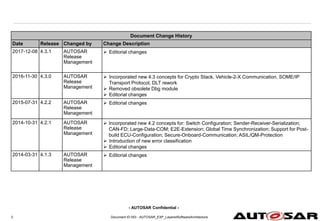
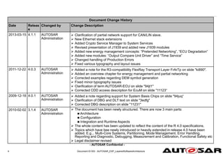
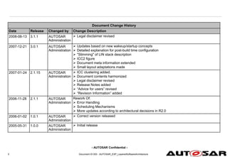

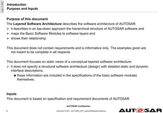
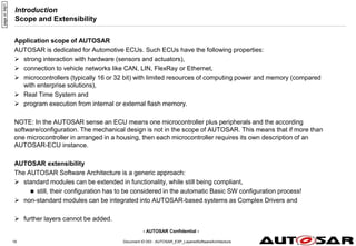
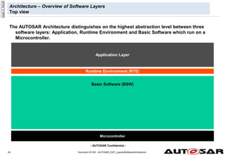
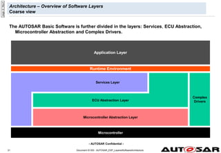
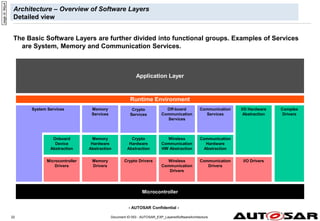
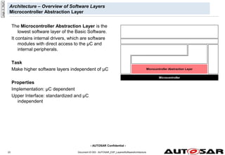
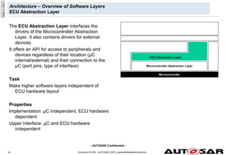
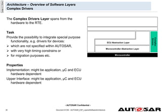
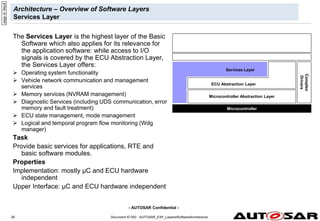
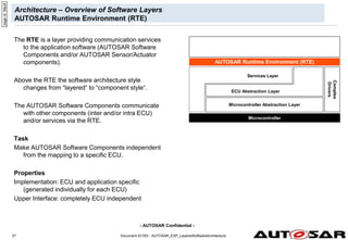
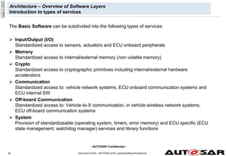
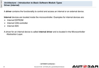
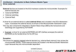
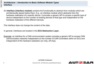
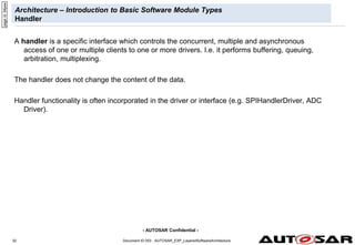
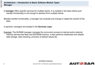
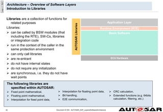

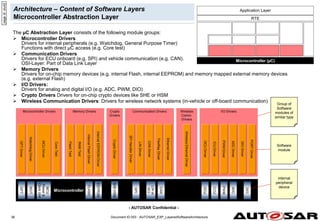
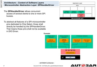
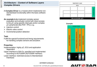
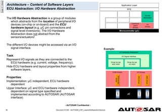
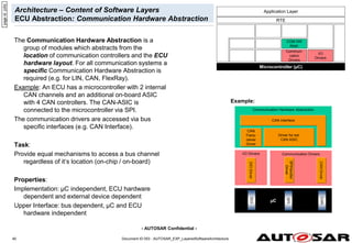
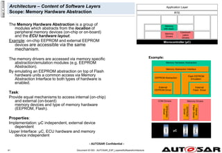
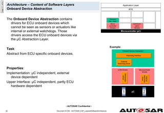
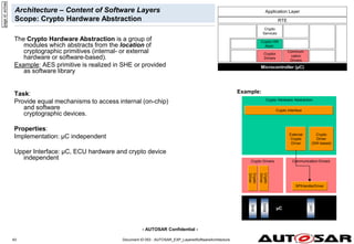
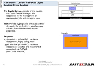
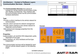
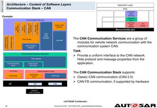
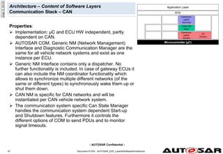

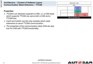
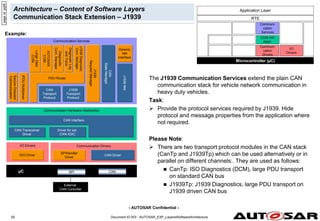
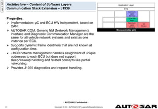
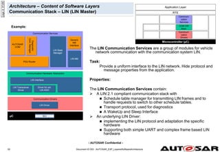
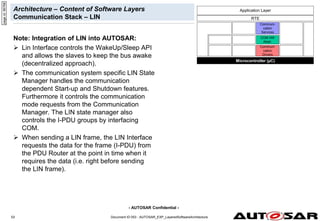
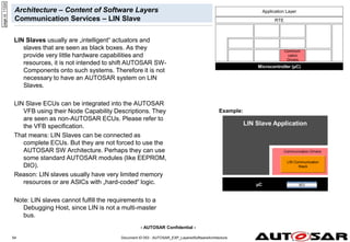
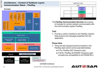
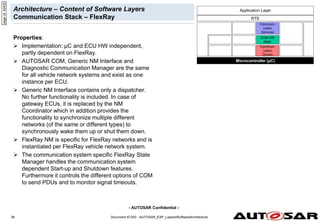
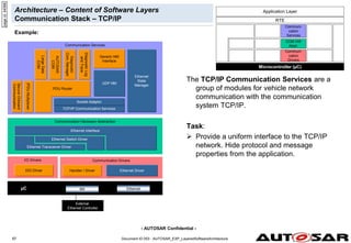
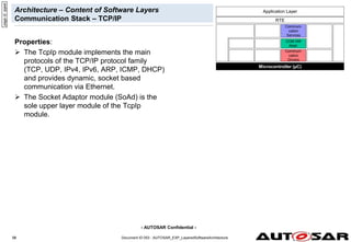
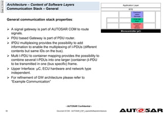
![- AUTOSAR Confidential -
Document ID 053 : AUTOSAR_EXP_LayeredSoftwareArchitecture
60
60
Architecture – Content of Software Layers
Off-board Communication Stack – Vehicle-2-X
The Off-board Communication Services are
a group of modules for Vehicle-to-X
communication via an ad-hoc wireless
network.
Facilities: implement the functionality for reception and
transmission of standardized V2X messages, build the
interface for vehicle specific SW-Cs
Basic Transport Protocol = Layer 4
Geo-Networking = Layer 3 (Addressing based on
geographic areas, the respective Ethernet frames have
their own Ether-Type)
V2X Management: manages cross-layer functionality
(like dynamic congestion control, security, position and
time)
Task:
Provide a uniform interface to the Wireless
Ethernet network. Hide protocol and
message properties from the application.
Microcontroller (µC)
Wireless
Comm.Drivers
Wireless
Comm. HwA
RTE
Off-board
Comm.
Services
COM HW
Abstr.
I/O
Drivers
Application Layer
page
id:
4wcs6
Example:
I/O Drivers
Off-board Communication Services
Wireless Communication Drivers
[Wireless / Wired] Communication Hardware Abstraction
Wireless Ethernet Driver
Handler / Driver
µC SPI Wireless Ethernet
External
Wireless Ethernet Controller
DIO Driver
Ethernet Interface
Wireless Ethernet Transceiver Driver
V2X Geo
Networking
V2X Basic
Transport
Protocol
V2X Facilities
V2X
Management](https://image.slidesharecdn.com/autosarexplayeredsoftwarearchitecture-230816140523-c9218429/85/AUTOSAR_EXP_LayeredSoftwareArchitecture-pdf-50-320.jpg)
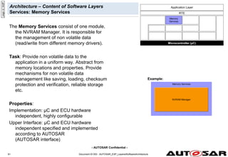

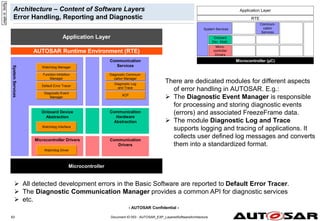
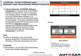
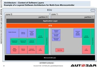
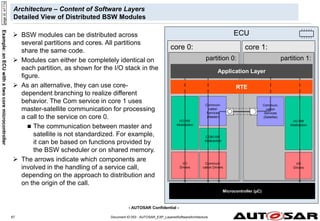
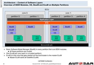
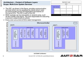
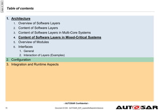
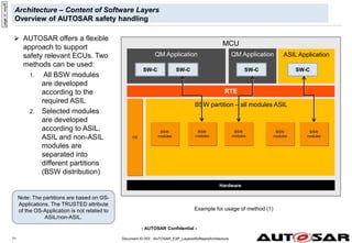
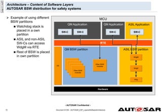
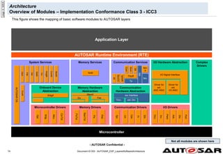
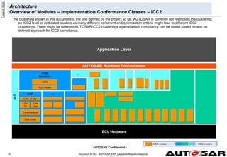
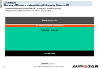
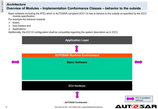
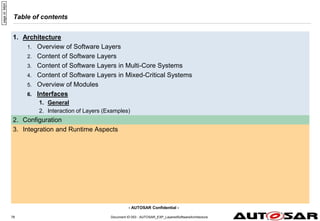
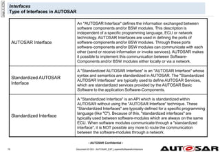
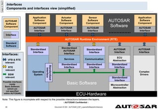
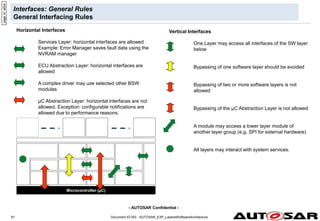
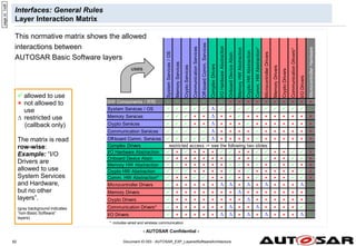
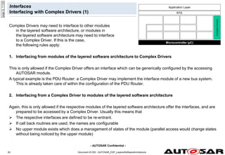
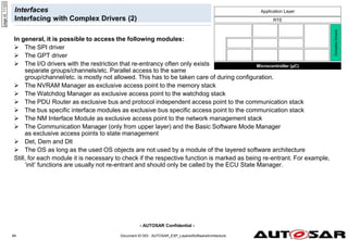
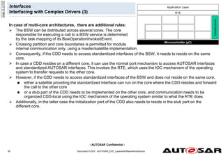
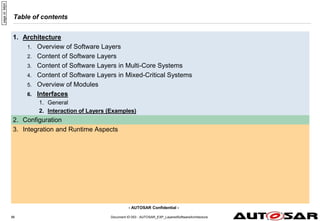
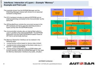
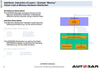
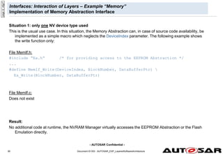
![- AUTOSAR Confidential -
Document ID 053 : AUTOSAR_EXP_LayeredSoftwareArchitecture
91
Interfaces: Interaction of Layers – Example “Memory”
Implementation of Memory Abstraction Interface
Situation 2: two or more different types of NV devices used
In this case the DeviceIndex has to be used for selecting the correct NV device. The implementation can also
be very efficient by using an array of pointers to function. The following example shows the write function
only:
File MemIf.h:
extern const WriteFctPtrType WriteFctPtr[2];
#define MemIf_Write(DeviceIndex, BlockNumber, DataBufferPtr)
WriteFctPtr[DeviceIndex](BlockNumber, DataBufferPtr)
File MemIf.c:
#include “Ea.h“ /* for getting the API function addresses */
#include “Fee.h“ /* for getting the API function addresses */
#include “MemIf.h“ /* for getting the WriteFctPtrType */
const WriteFctPtrType WriteFctPtr[2] = {Ea_Write, Fee_Write};
Result:
The same code and runtime is needed as if the function pointer tables would be inside the NVRAM Manager.
The Memory Abstraction Interface causes no overhead.
page
id:
12345](https://image.slidesharecdn.com/autosarexplayeredsoftwarearchitecture-230816140523-c9218429/85/AUTOSAR_EXP_LayeredSoftwareArchitecture-pdf-81-320.jpg)
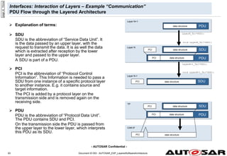
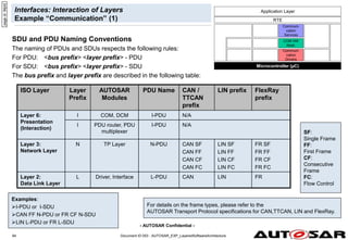
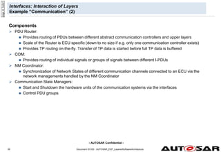
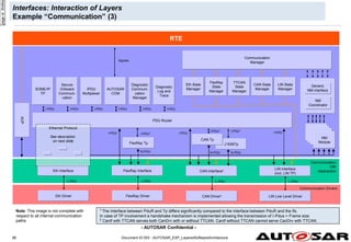
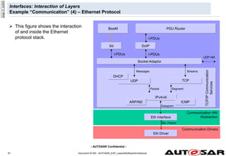
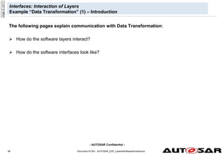
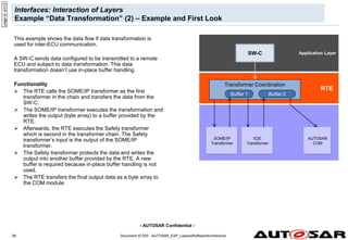
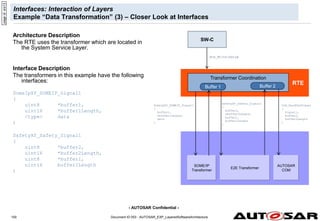
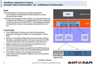
![- AUTOSAR Confidential -
Configuration
Overview
The AUTOSAR Basic Software supports the following configuration classes:
1. Pre-compile time
Preprocessor instructions
Code generation (selection or synthetization)
2. Link time
Constant data outside the module; the data can be configured after the module has been
compiled
3. Post-build time
Loadable constant data outside the module. Very similar to [2], but the data is located in a
specific memory segment that allows reloading (e.g. reflashing in ECU production line)
Independent of the configuration class, single or multiple configuration sets can be provided by means
of variation points. In case that multiple configuration sets are provided, the actually used configuration
set is to be chosen at runtime in case the variation points are bound at run-time.
In many cases, the configuration parameters of one module will be of different configuration classes.
Example: a module providing Post-build time configuration parameters will still have some parameters
that are Pre-compile time configurable.
Note: Multiple configuration sets were modeled as a sub class of the Post-build time configuration class
up to AUTOSAR 4.1.x.
Document ID 053 : AUTOSAR_EXP_LayeredSoftwareArchitecture
103
page
id:
9000a](https://image.slidesharecdn.com/autosarexplayeredsoftwarearchitecture-230816140523-c9218429/85/AUTOSAR_EXP_LayeredSoftwareArchitecture-pdf-93-320.jpg)
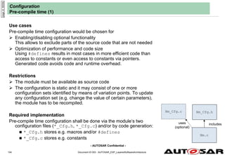
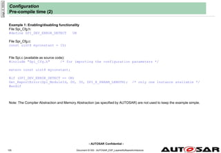
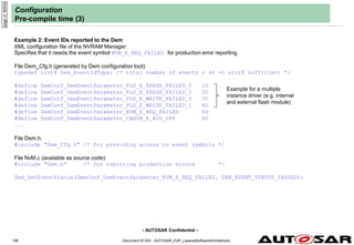
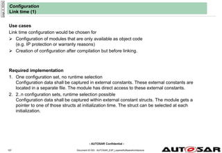
![- AUTOSAR Confidential -
Document ID 053 : AUTOSAR_EXP_LayeredSoftwareArchitecture
108
Configuration
Link time (2)
Example 1: Event IDs reported to the Dem by a multiple instantiated module (Flash Driver) only available as object code
XML configuration file of the Flash Driver:
Specifies that it needs the event symbol FLS_E_WRITE_FAILED for production error reporting.
File Dem_Cfg.h (generated by Dem configuration tool):
typedef uint16 Dem_EventIdType; /* total number of events = 380 => uint16 required */
#define DemConf_DemEventParameter_FLS_E_ERASE_FAILED_0 1U
#define DemConf_DemEventParameter_FLS_E_ERASE_FAILED_1 2U
#define DemConf_DemEventParameter_FLS_E_WRITE_FAILED_0 3U
#define DemConf_DemEventParameter_FLS_E_WRITE_FAILED_1 4U
#define DemConf_DemEventParameter_NVM_E_REQ_FAILED 5U
#define DemConf_DemEventParameter_CANSM_E_BUS_OFF 6U
...
File Fls_Lcfg.c:
#include "Dem_Cfg.h" /* for providing access to event symbols */
const Dem_EventIdType Fls_WriteFailed[2] = {DemConf_DemEventParameter_FLS_E_WRITE_FAILED_1,
DemConf_DemEventParameter_FLS_E_WRITE_FAILED_2};
File Fls.c (available as object code):
#include "Dem.h" /* for reporting production errors */
extern const Dem_EventIdType Fls_WriteFailed[];
Dem_SetEventStatus(Fls_WriteFailed[instance], DEM_EVENT_STATUS_FAILED);
Note: the complete include file structure with all forward declarations is not shown here to keep the example simple.
page
id:
9000f](https://image.slidesharecdn.com/autosarexplayeredsoftwarearchitecture-230816140523-c9218429/85/AUTOSAR_EXP_LayeredSoftwareArchitecture-pdf-98-320.jpg)
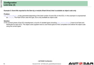
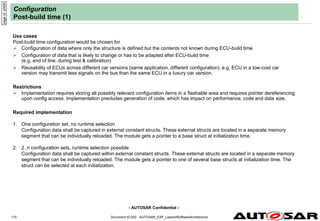
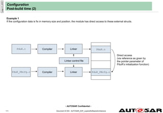
![- AUTOSAR Confidential -
Document ID 053 : AUTOSAR_EXP_LayeredSoftwareArchitecture
112
Configuration
Post-build time (3)
Required implementation 2: Configuration of CAN Driver that is available as object code only; a configuration set can be
selected out of multiple configuration sets during initialization time.
page
id:
y000k
Compiler
File Can_PBcfg.c:
#include “Can.h” /* for getting Can_ConfigType */
const Can_ConfigType MySimpleCanConfig [2] =
{
{
Can_BitTiming = 0xDF,
Can_AcceptanceMask1 = 0xFFFFFFFF,
Can_AcceptanceMask2 = 0xFFFFFFFF,
Can_AcceptanceMask3 = 0x00034DFF,
Can_AcceptanceMask4 = 0x00FF0000
},
{ … }
};
File EcuM.c:
#include “Can.h“ /* for initializing the CAN Driver */
Can_Init(&MySimpleCanConfig[0]);
File Can.c (available as object code):
#include “Can.h“ /* for getting Can_ConfigType */
void Can_Init(Can_ConfigType* Config)
{
/* write the init data to the CAN HW */
};
Linker
Binary file](https://image.slidesharecdn.com/autosarexplayeredsoftwarearchitecture-230816140523-c9218429/85/AUTOSAR_EXP_LayeredSoftwareArchitecture-pdf-102-320.jpg)
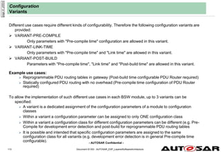
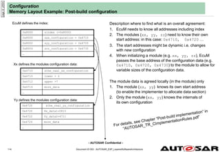
![- AUTOSAR Confidential -
Document ID 053 : AUTOSAR_EXP_LayeredSoftwareArchitecture
115
Configuration
Memory Layout Example: Multiple configuration sets
page
id:
axcvb
0x8000 &index[] (=0x8000)
0x8000 &xx_configuration = 0x4710
0x8002 &yy_configuration = 0x4720
0x8004 &zz_configuration = 0x4730
…
0x8008 &xx_configuration = 0x5000
0x800a &yy_configuration = 0x5400
0x800c &zz_configuration = 0x5200
…
0x8010 &xx_configuration = …
0x8012 &yy_configuration = …
0x8014 &zz_configuration = …
…
FL
FR
RL
As before, the description where to find what is an
overall agreement
1. The index contains more than one description (FL,
FR,..) in an array
(here the size of an array element is agreed to be
8)
2. There is an agreed variable containing the position
of one description
selector = CheckPinCombination()
3. Instead of passing the pointer directly there is one
indirection:
(struct EcuM_ConfigType *) &index[selector];
4. Everything else works as in conventional single
configuration case.](https://image.slidesharecdn.com/autosarexplayeredsoftwarearchitecture-230816140523-c9218429/85/AUTOSAR_EXP_LayeredSoftwareArchitecture-pdf-105-320.jpg)