Downloaded 11 times
![G. Laxminarayana, G.Bhargavi / International Journal of Engineering Research and
Applications (IJERA) ISSN: 2248-9622 www.ijera.com
Vol. 3, Issue 4, Jul-Aug 2013, pp.1281-1286
1281 | P a g e
Simulation Of An Efficient AC–DC Step-Up Converter For Low-
Voltage Energy Harvesting
G. Laxminarayana1
, G.Bhargavi2
Assistant Professor, Dept.of EEE, Aurora’s Engineering College, Bhongir, India1
M.Tech Scholar, Dept.of EEE, Aurora’s Engineering College, Bhongir, India2
Abstract
In this paper direct AC to DC is
converted by proposed model from low AC
voltage to high DC voltage in single stage
conversion. And this paper presents an efficient
AC to DC power that avoids the bridge
rectification and directly converts low AC input
voltage to high DC output voltage. This proposed
converter consists boost converter and buck-boost
converter both are connected in parallel to process
the positive and negative half cycles of the input
voltage. Analysis of the converter is carried out.
Simulation results are presented to validate the
proposed converter topology and control scheme.
Index Terms—AC–DC conversion, boost
converter, energy harvesting, low power, low
voltage, power converter control.
I. INTRODUCTION
Normally self powered devices harvest the
ambient energies by microgenerators and having
without any continuous power supply. Many types of
misrogenerators used for harvesting different forms
of ambient energies [1]-[8]. The types of generators
are electromagnetic, electrostatic and piezoelectric
[5]-[10],[12]-[16]. Compare with all types of
microgenerators electromagnetic microgenerators
have the highest energy density. In this study
electromagnetic generator is considered. The power
level of inertial microgenerators is very low ranging
from few micro watts to tens of milliwatts. In
practical , electromagnetic micro generators are
spring-mass-damper based resonance system shown
in fig(1). In this, the small amplitude mechanical
vibrations are amplifeied into larger amplitude
translation movements. The functionality of the
power converter is important than the maximum
energy conversion. The output voltage of
electromagnetic microgenerator is ac type but all
electronic loads require dc voltage for further
operation. Due to the practical size limitations the
outputs of electromagnetic micro generator is very
low(few 100mv), where the electronic loads require
higher dc voltage(3.3v)
Fig 1. Schematic diagram of a resonance inertial
microgenerator
In conventional power converters the ac –to
–dc conversion is taken place by two stages that are
first, diode bridge rectification and second power
converters (standard buck or boost converter) to
boost the ouput voltage(fig.2.). the existing power
converter model have the major disadvantages that
are first, the diode bridge rectification is not feasible
for very low voltage electromagnetic
microgenerators. Second, if diode bridge rectification
is feasible, the forward voltage drops in the diode
will cause a large amount of losses and make the
power converter is inefficient.
To achieve the problems of the previous
converter model direct ac-to-dc is proposed
[10],[13],[15]. In this proposed converter model,
bridge rectification is avoided and the microgenerator
power is processed by single stage boost type power
converter (fig3). In this tcleype power converter the
output dc split into two series connected capacitors
and each capacitor charged for only one half cycle
the microgenerator output voltage. The time periods
of the resonance-based microgenerators output
voltages are normally milliseconds, very large
voltage drops will occur in the capacitors during the
half cycles when the capacitors are not charged by
the converter. In practical, large capacitors will
required to achieve the allowable voltage ripple at dc
bus output. This is not applicable for microgenerators
because of practical size limitations.](https://image.slidesharecdn.com/gz3412811286-130718235053-phpapp01/85/Gz3412811286-1-320.jpg)
![G. Laxminarayana, G.Bhargavi / International Journal of Engineering Research and
Applications (IJERA) ISSN: 2248-9622 www.ijera.com
Vol. 3, Issue 4, Jul-Aug 2013, pp.1281-1286
1282 | P a g e
Fig 2. Conventional two stage power conversion
model
Fig 3. Proposed converter model (Direct ac-to-dc
conversion)
The direct ac-to-dc converter is proposed in
[21]. The proposed converter represented in fig4.
The circuit consists of boost converter (Switch S1,
inductor L1, Diode D1) and buck- boost converter
(Switch S2, inductor L2, Diode D2). These two
converters are connected in parallel. The operation
of the converter model consists total four modes. For
positive half cycle boost converter switch S1 is turned
ON, and inductor L1 stores the energy and
dischargers through the Diode D1 and Capacitor. For
negative half cycle buck-boost converter Switch S2 is
turned ON, and inductor L2 stores the energy and
dischargers through Diode D2 and capacitor.
The converter is designed to operate in
DCM mode. By this mode of operation switching
losses and diode reverse recovery will be reduces.
And the control scheme of the DCM is simpler than
the CCM. For constant duty cycle operation DCM
operation , the input current of the converter is
proportional to the input voltage at every switching
cycle.
Fig 4. Proposed direct ac-to-de model.
II. DIRECT AC-TO-DC CONVERTER
The proposed power converter is direct ac-
to-dc power consisting of one boost converter and
one buck-boost converter. These two converters are
connected in parallel. The operation of the circuit is
discussed in[21].
A. Converter analysis
Consider the input current waveform of the
converter as shown in Fig. 5(a). It can be noted that
during the boost converter operation, the input
current i and the boost inductor current (iL1 ) are
equal, but during the buck–boost converter operation,
the input current i and the current in buck–boost
inductor (iL2 ) are not equal. This is because, in the
buck–boost converter the input current becomes zero
during the switch turn OFF period (TOFF).
Therefore, in a switching cycle, the energy
transferred to the output by a buck–boost converter is
equal to the energy stored in the inductor, whereas, in
the boost converter, the energy transferred to the
output is more than the energy stored in the inductor.
Hence, for the equal duty cycles, input voltages and
inductor values (L1 = L2 ), the total powers delivered
by the two converters over an input voltage cycle are
not equal. In this section, analyses of the converters
are carried out and the relations between the control
and circuit parameters of the boost and the buck–
boost converters pertaining to the input power and
the output power are obtained.
B. Converter analysis and control
Fig. 5: Input current, gate drive signal and input
voltage during a
boost converter switching cycle.
Consider the input current waveform of the converter
and various variables as defined in Fig 4. The
average input power, Pib, of the converter can be
obtained as :
(1)](https://image.slidesharecdn.com/gz3412811286-130718235053-phpapp01/85/Gz3412811286-2-320.jpg)
![G. Laxminarayana, G.Bhargavi / International Journal of Engineering Research and
Applications (IJERA) ISSN: 2248-9622 www.ijera.com
Vol. 3, Issue 4, Jul-Aug 2013, pp.1281-1286
1285 | P a g e
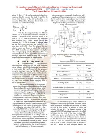
To calculate the power losses in the various
components of the converter, the currents in the
components of the converter circuits were measured
and the values of the parasitic components (see Table
I) were estimated. The measured currents, voltages,
and the estimated component values were used to
calculate the loss components analytically. In Table
II, various loss components of the converter for the
load resistance R = 200 Ω are presented. The power
consumed by the entire control circuit is estimated.
From this loss analysis, the estimated converter
efficiency is 63.8%. This estimation agrees with the
measurements and earlier simulation results. Further,
it is found that in the case of inductor loss, about 70%
of the total loss is due to the copper loss and the
remaining 30% loss is due to the magnetic losses.
Hence, with proper design of the conductor and the
magnetic components, the converter efficiency can be
improved. In the case of MOSFET loss, about 93% of
the total loss is caused by the conduction loss and the
remaining loss is due to the switching loss.
Therefore, with the use of larger MOSFETs with
lower ON-state resistance (Rds ON), the efficiency
can be further improved. It can be noted that the
efficiency of the converter, proposed in this study, is
higher than the efficiency of the reported energy
harvesting converters (44%
in [20]).
V. CONCLUSION
The presented direct ac-to-dc low voltage
energy-harvesting converter avoids the conventional
bridge rectification and achieves higher efficiency.
The proposed converter consists of a boost converter
in parallel with a buck–boost converter. The negative
gain of the buck–boost converter is utilized to boost
the voltage of the negative half cycle of the
microgenerator to positive dc voltage. Operation of
on state resistance efficiency has been improved. the
proposed converter can also be successfully used for
maximum energy harvesting.
REFERENCES
[1] J. A. Paradiso and T. Starner, “Energy
scavenging for mobile and wireless
electronics,” IEEE Pervasive Comput., vol.
4, no. 1, pp. 18–27, Jan./Mar. 2005.
[2] S. Meninger, J. O. Mur-Miranda, R.
Amirtharajah, A. P. Chandrakasan, and J. H.
Lang, “Vibration-to-electric energy
conversion,” IEEE Trans. Very Large Scale
Integr. Syst., vol. 9, no. 1, pp. 64–76, Feb.
2001.
[3] M. El-Hami, P. Glynne-Jones, N. M. White,
M. Hill, S. Beeby, E. James, A. D. Brown,
and J. N. Ross, “Design and fabrication of a
new vibration based electromechanical
power generator,” Sens. Actuators A: Phys.,
vol. 92, pp. 335–342, 2001.
[4] T. M. Thul, S. Dwari, R. D. Lorenz, and L.
Parsa, “Energy harvesting and efficient
power generation from human activities,” in
Proc. Center Power Electron. Syst. (CPES)
Semin., Apr. 2007, pp. 452–456.
[5] N. G. Stephen, “On energy harvesting from
ambient vibration,” J. Sound Vibrations, vol.
293, pp. 409–425, 2006.
[6] J. R. Amirtharajah and A. P. Chandrakasan,
“Self-powered signal processing using
vibration-based power generation,” IEEE J.
Solid-State Circuits, vol. 33, no. 5, pp. 687–
695, May 1998.
[7] B. H. Stark, P. D. Mitcheson, M. Peng, T. C.
Green, E. Yeatman, and A. S. Holmes,
“Converter circuit design, semiconductor
device selection and analysis of parasitics
for micropower electrostatic generators,”
IEEE Trans. Power Electron., vol. 21, no. 1,
pp. 27–37, Jan. 2006.
[8] C. B. Williams and R. B. Yates, “Analysis
of a micro-electric generator for
microsystems,” in Proc. Int. Conf. Solid-
State Sens. Actuators, 1995, pp. 369–372.
[9] P.D.Mitcheson, T. C. Green, E.M.Yeatman,
and A. S. Holmes, “Architectures for
vibration-driven micropower generators,” J.
Microelectromech. Syst., vol. 13, no. 3, pp.
429–440, Jun. 2004.
[10] S. Xu, K. D. T. Ngo, T. Nishida, G. B.
Chung, and A. Sharma, “Low frequency
pulsed resonant converter for energy
harvesting,” IEEE Trans Power Electron.,
vol. 22, no. 1, pp. 63–68, Jan. 2007.
[11] J. Elmes, V. Gaydarzhiev, A.Mensah, K.
Rustom, J. Shen, and I. Batarseh,
“Maximum energy harvesting control for](https://image.slidesharecdn.com/gz3412811286-130718235053-phpapp01/85/Gz3412811286-5-320.jpg)
![G. Laxminarayana, G.Bhargavi / International Journal of Engineering Research and
Applications (IJERA) ISSN: 2248-9622 www.ijera.com
Vol. 3, Issue 4, Jul-Aug 2013, pp.1281-1286
1286 | P a g e
oscillating energy harvesting systems,” in
Proc. IEEE Power Electron. Spec. Conf.,
Jun. 2007, pp. 2792– 2798.
[12] S. P. Beeby, R. N. Torah, M. J. Tudor, P.
Glynne-Jones, T. O’Donnell, C. R. Saha,
and S. Roy, “Micro electromagnetic
generator for vibration energy harvesting,”
J. Micromech. Microeng., vol. 17, pp. 1257–
1265, 2007.
[13] B. H. Stark, P. D. Mitcheson, M. Peng, T. C.
Green, E. Yeatman, and A. S. Holmes,
“Converter circuit design, semiconductor
device selection and analysis of parasitics
for micropower electrostatic generators,”
IEEE Trans. Power Electron., vol. 21, no. 1,
pp. 27–37, Jan. 2006.
[14] T. Paing, J. Shin, R. Zane, and Z. Popovic,
“Resistor emulation approach to low-power
RF energy harvesting,” IEEE Trans. Power
Electron., vol. 23, no. 3, pp. 1494–1501,
May 2008.
[15] E. Lefeuvre, D. Audigier, C. Richard, and D.
Guyomar, “Buck-boost converter for
sensorless power optimization of
piezoelectric energy harvester,” IEEE Trans.
Power Electron., vol. 22, no. 5, pp. 2018–
2025, Sep. 2007.
[16] X. Cao,W.-J. Chiang,Y.-C.King, andY.-K.
Lee, “Electromagnetic energy harvesting
circuit with feedforward and feedback DC–
DC PWM boost converter for vibration
power generator system,” IEEE Trans.
Power Electron., vol. 22, no. 2, pp. 679–
685, Mar. 2007.
[17] G. K. Ottman, H. F. Hofmann, and G. A.
Lesieutre, “Optimized piezoelectric energy
harvesting circuit using step-down converter
in discontinuous conduction mode,” IEEE
Trans. Power Electron., vol. 18, no. 2, pp.
696– 703, Mar. 2003.
[18] G. K. Ottman, H. F. Hofmann, A. C. Bhatt,
and G. A. Lesieutre, “Adaptive piezoelectric
energy harvesting circuit for wireless remote
power supply,” IEEE Trans. Power
Electron., vol. 17, no. 5, pp. 669–676, Sep.
2002.
[19] M. Ferrari, V. Ferrari, D. Marioli, and A.
Taroni, “Modeling, fabrication and
performance measurements of a
piezoelectric energy converter for power
harvesting in autonomous microsystems,”
IEEE Trans. Instrum. Meas., vol. 55, no. 6,
pp. 2096–2101, Dec. 2006.
[20] P. D. Mitcheson, T. C. Green, E. M.
Yeatman, and A. S. Holmes, “Power
processing circuits for electromagnetic,
electrostatic and piezoelectric inertial energy
scavengers,” Microsyst. Technol., vol. 13,
pp. 1629–1635, May 2007.
[21] S. Dwari, R. Dayal, and L. Parsa, “A novel
direct AC/DC converter for efficient low
voltage energy harvesting,” in Proc. IEEE
Ind. Electron. Soc. Annu. Conf., Nov. 2008,
pp. 484–488.
[22] A. Richelli, L. Colalongo, S. Tonoli, and
Z.M. Kov´acs-Vajna, “A 0.2−1.2 VDC/DC
boost converter for power harvesting
applications,” IEEE Trans. Power Electron.,
vol. 24, no. 6, pp. 1541–1546, Jun. 2009.
[23] J. C. Salmon, “Circuit topologies for single-
phase voltage-doubler boost rectifiers,”
IEEE Trans. Power Electron., vol. 8, no. 4,
pp. 521–529, Oct 1993.
G.Laxminarayana received the B. Tech.
degree in Electrical and Electronics Engineering from
JNT University and M.Tech in Power Electronics
Engineering in Aurora’s Engineering College (JNTU
Hyderabad. He is currently working as a Assistant
Professor in Aurora’s Engineering College. He is
working toward the Ph.D. degree in Electrical
Engineering.
G.Bharagvi received the B. Tech. degree in
Electrical and Electronics Engineering from
JNTUniversity and pursuing M.Tech in Power
Electronics in Aurora’s Engineering College (JNTU
Hyderabad).](https://image.slidesharecdn.com/gz3412811286-130718235053-phpapp01/85/Gz3412811286-6-320.jpg)

This paper presents a direct AC to DC power converter designed for low-voltage energy harvesting, which utilizes a single-stage conversion to effectively avoid issues associated with conventional bridge rectification. The proposed converter integrates a boost converter and a buck-boost converter operating in parallel for enhanced efficiency, specifically addressing the challenges presented by low voltage inputs from electromagnetic microgenerators. Simulation results indicate that the converter can successfully step up low AC voltages to a higher DC output, demonstrating improved operational efficiency compared to existing models.


![5G Explained! A High Level Overview [Introduction]](https://cdn.slidesharecdn.com/ss_thumbnails/5gexplainedahighleveloverview-260119165306-cc137a3e-thumbnail.jpg?width=640&height=640&fit=bounds)


