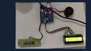
TITLE: IOT BASED AUTOMATIC
COLLEGE BELL TIMER
PRESENTED BY:
S.ABARNA [22TH0201]
S.DEVADHARSHINI [22TH0220]
S.H.FOUZIYA[22TH0227]
D.HEMAVARSHINI [22TH0231]
S.SWATHI [22TH0306]
PROJECT GUIDE:
MRS.S.SARANYA
MANAKULA VINAYAGAR INSTITUTE OF TECHNOLOGY
DEPARTMENT OF INFORMATION TECHNOLOGY
The main objective of this project is to implement
an Automatic college bell system using an Arduino.
In this Arduino based college bell circuit, we used
three major components which are IC RTCDS1307,
Arduino Uno Board, and 16x2 LCD modules. Here,
Arduino is used for reading time from ds1307 and
display it on 16x2 LCD. DS1307 sends time/date
using 2 lines to arduino. A buzzer is also used for
alarm indication, which beeps when alarm is
activated.
INTRODUCTION:
LCD DISPLAY
16*2
KEYPAD
3*1
BUZZER ARDUINO UNO
Block Diagram:
COMPONENTS
Arduino UNO.
16×2 LCD.
10K-ohm potentiometer.
Buzzer.
Three pushbuttons.
Jumper wires.
Breadboard.
USB cable for uploading the code.
3 X 1 Keypad.
Arduino UNO
Arduinoisasoftwareaswellashardware platform that
helps in making electronic projects.
Arduinoboardsareabletoreadinputs- lightonasensor,
afingeronabutton,or aTwittermessage-andturnitinto
an output-activating a motor,turningon an LED,
publishingsomethingonline.
A16*2LCDdisplayisaliquidcrystaldisplay thatcan
show16charactersineachofitstwo rows,providinga
totalof32charactersof information.
It’scommonlyusedtodisplayalphanumeric
informationinvariouselectronicdevices
16*2 LCD DISPLAY
A buzzer orbeeperis an audio signaling device,
which may be mechanical, electromechanical,
or piezoelectric.
Typical uses of buzzers include alarm
devices, timers, train, etc,..
BUZZER
KEYPAD
A SMALL USUALLY NUMERICAL
KEYBOARD.
A S M ALL S ET OF KEYS THAT IS PART OFA
LARGER KEYBOARD OR ANOTHER DEVIC E
(S UC H AS A TELEPHONE OR CALCULATOR)
ON THE POWER SUPPLY OF THE CIRCUIT THE BRIDGE CIRCUIT
CONVERTS THE AC SUPPLY INTO DC SUPPLY AND VOLTAGE
REGULATOR REGULATES THE SUPPLY.
ON THE LED WECAN ABLE TO VIEWTIME FORMAT AS PERIOD AND
SECONDS THROUGH OUTPUT PORT.
THE ELECTRONIC CIRCUIT RECEIVESSIGNAL AND DRIVES
CORRESPONDING RELAY.
THE RELAY ISUSED AS A SWITCHTO OPERATE THE BELL.
WEPROGRAMMED THIS PROJECT AS TO HEAR THE BUZZER SOUND
EVERY AFTERONE HOURAND WE CAN DISPLAY AS PERTHE
SCHEDULE IN THE PROGRAM.
WORKING:
INITIAL DISPLAY:
PERIOD 1:
• Used in educational institutes, colleges, schools.
• Can also beused in industries.
• It is an automatic system.
• Human errorscan beavoided.
• Safety isassured.
ADVANTAGES:
CONCLUSION:
• Present day ringingbell in colleges or schools are carried out manually.
• The main disadvantage of this is that one person has to be alert forthis.
• To overcome this, we have decided to prepare the circuit which will be operated
automaticallyandtheringingofbellwillstart by itsgiventime.
AUTOMATIC COLLEGE BELL TIMER using  IoT.pptx

AUTOMATIC COLLEGE BELL TIMER using IoT.pptx

  • 1.
    TITLE: IOT BASEDAUTOMATIC COLLEGE BELL TIMER PRESENTED BY: S.ABARNA [22TH0201] S.DEVADHARSHINI [22TH0220] S.H.FOUZIYA[22TH0227] D.HEMAVARSHINI [22TH0231] S.SWATHI [22TH0306] PROJECT GUIDE: MRS.S.SARANYA MANAKULA VINAYAGAR INSTITUTE OF TECHNOLOGY DEPARTMENT OF INFORMATION TECHNOLOGY
  • 2.
    The main objectiveof this project is to implement an Automatic college bell system using an Arduino. In this Arduino based college bell circuit, we used three major components which are IC RTCDS1307, Arduino Uno Board, and 16x2 LCD modules. Here, Arduino is used for reading time from ds1307 and display it on 16x2 LCD. DS1307 sends time/date using 2 lines to arduino. A buzzer is also used for alarm indication, which beeps when alarm is activated. INTRODUCTION:
  • 3.
  • 4.
    COMPONENTS Arduino UNO. 16×2 LCD. 10K-ohmpotentiometer. Buzzer. Three pushbuttons. Jumper wires. Breadboard. USB cable for uploading the code. 3 X 1 Keypad.
  • 6.
    Arduino UNO Arduinoisasoftwareaswellashardware platformthat helps in making electronic projects. Arduinoboardsareabletoreadinputs- lightonasensor, afingeronabutton,or aTwittermessage-andturnitinto an output-activating a motor,turningon an LED, publishingsomethingonline.
  • 7.
    A16*2LCDdisplayisaliquidcrystaldisplay thatcan show16charactersineachofitstwo rows,providinga totalof32charactersofinformation. It’scommonlyusedtodisplayalphanumeric informationinvariouselectronicdevices 16*2 LCD DISPLAY
  • 8.
    A buzzer orbeeperisan audio signaling device, which may be mechanical, electromechanical, or piezoelectric. Typical uses of buzzers include alarm devices, timers, train, etc,.. BUZZER
  • 9.
    KEYPAD A SMALL USUALLYNUMERICAL KEYBOARD. A S M ALL S ET OF KEYS THAT IS PART OFA LARGER KEYBOARD OR ANOTHER DEVIC E (S UC H AS A TELEPHONE OR CALCULATOR)
  • 10.
    ON THE POWERSUPPLY OF THE CIRCUIT THE BRIDGE CIRCUIT CONVERTS THE AC SUPPLY INTO DC SUPPLY AND VOLTAGE REGULATOR REGULATES THE SUPPLY. ON THE LED WECAN ABLE TO VIEWTIME FORMAT AS PERIOD AND SECONDS THROUGH OUTPUT PORT. THE ELECTRONIC CIRCUIT RECEIVESSIGNAL AND DRIVES CORRESPONDING RELAY. THE RELAY ISUSED AS A SWITCHTO OPERATE THE BELL. WEPROGRAMMED THIS PROJECT AS TO HEAR THE BUZZER SOUND EVERY AFTERONE HOURAND WE CAN DISPLAY AS PERTHE SCHEDULE IN THE PROGRAM. WORKING:
  • 11.
  • 12.
  • 13.
    • Used ineducational institutes, colleges, schools. • Can also beused in industries. • It is an automatic system. • Human errorscan beavoided. • Safety isassured. ADVANTAGES:
  • 14.
    CONCLUSION: • Present dayringingbell in colleges or schools are carried out manually. • The main disadvantage of this is that one person has to be alert forthis. • To overcome this, we have decided to prepare the circuit which will be operated automaticallyandtheringingofbellwillstart by itsgiventime.