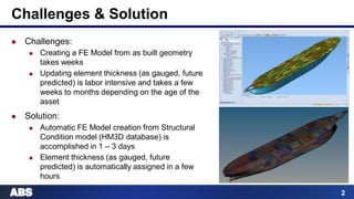
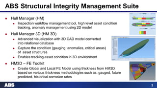
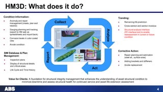
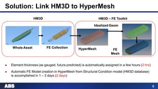
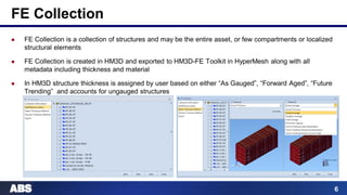
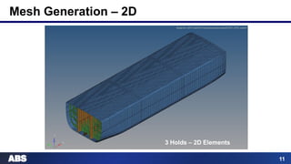
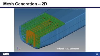
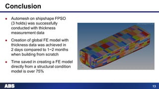
©2015 American Bureau of Shipping. All rights reserved.
Eka Kristanto, Sameer Kalghatgi, Chris Serratella
ABS Asset Integrity Management Team
Houston, TX
8 October 2015
Automated Finite Element Model Creation
using Structural Condition Data
for Marine & Offshore Assets
ALTAIR TECHNOLOGY CONFERENCE
2
Challenges & Solution
 Challenges:
 Creating a FE Model from as built geometry
takes weeks
 Updating element thickness (as gauged, future
predicted) is labor intensive and takes a few
weeks to months depending on the age of the
asset
 Solution:
 Automatic FE Model creation from Structural
Condition model (HM3D database) is
accomplished in 1 – 3 days
 Element thickness (as gauged, future
predicted) is automatically assigned in a few
hours
3
ABS Structural Integrity Management Suite
 Hull Manager (HM)
 Inspection workflow management tool, high level asset condition
tracking, anomaly management using 2D model
 Hull Manager 3D (HM 3D)
 Advanced visualization with 3D CAD model converted
into relational database
 Capture the condition (gauging, anomalies, critical areas)
of asset structures
 Enables tracking asset condition in 3D environment
 HM3D – FE Toolkit
 Create Global and Local FE Model using thickness from HM3D
based on various thickness methodologies such as: gauged, future
predicted, historical corrosion rates
4
HM3D: What does it do?
Condition Information:
 Anomaly and repair
management (create, plan and
resolve)
 Gauging planning and tracking
(export to HM web as
spreadsheets and import back)
 Corrosion levels in color coded
view
 Anode condition
Trending:
 Remaining life prediction
 Cross-section and section modulus
 Structural analysis interface
(FE interface tool) to enable
reassessment in current or future
condition
Value for Clients: A foundation for structural integrity management that enhances the understanding of asset structural condition to
minimize downtime and assess structural health for continued service and asset life extension assessment
Collect
Corrective Action:
 Repair planning and estimation
(steel wt., surface area)
 Adding brackets and stiffeners
 Anode replacement
Analyze
Act
Report
SIM Database & Plan
Management:
 Inspection plans
 Display of structural details
and critical areas
 Life Cycle and Time History
5
Solution: Link HM3D to HyperMesh
HyperMesh
HM3D
FE Collection
FE
Mesh
Idealized Geom
HM3D – FE Toolkit
Whole Asset
 Element thickness (as gauged, future predicted) is automatically assigned in a few hours (2 hrs)
 Automatic FE Model creation in HyperMesh from Structural Condition model (HM3D database)
is accomplished in 1 – 3 days (2 days)
6
FE Collection
 FE Collection is a collection of structures and may be the entire asset, or few compartments or localized
structural elements
 FE Collection is created in HM3D and exported to HM3D-FE Toolkit in HyperMesh along with all
metadata including thickness and material
 In HM3D structure thickness is assigned by user based on either “As Gauged”, “Forward Aged”, “Future
Trending” and accounts for ungauged structures
7
Defeature & Idealization
 Raw Geometry
from HM3D is
defeatured and
idealized based on
custom rules
 Determines quality
of mesh
 Idealization (and
Mesh) is done
automatically
8
Defeature & Idealization
 Automated
idealization is rule
based
 User may also
determine how the
geometry needs to
be idealized
 User may edit
idealized geometry
prior to meshing
9
ABS Mesh Generation Rules
 Mesh Size and Density:
 Mesh sizes in longitudinal, transverse and vertical directions
 Mesh density between two adjacent web fames for and aft of a
transverse bulkhead
 Mesh density over the depth of the double bottom floors,
girder, side transverse webs, side stringers, vertical webs and
horizontal stringers on transverse bulkheads
 Mesh Shape:
 Aspect ratio ≤ 3
 Taper ≤ 10
 Warping ≤ 5 degree
 Internal angle ≥ 30 degree
10
Mesh Generation – 1D
3 Holds – 1D Elements
11
Mesh Generation – 2D
3 Holds – 2D Elements
12
Mesh Generation – 2D
Typical Bulkhead
Typical Stringer
Typical Frame
3 Holds – 2D Elements
13
Conclusion
 Automesh on shipshape FPSO
(3 holds) was successfully
conducted with thickness
measurement data
 Creation of global FE model with
thickness data was achieved in
2 days compared to 1~2 months
when building from scratch
 Time saved in creating a FE model
directly from a structural condition
model is over 75%
www.eagle.org
©2015 American Bureau of Shipping. All rights reserved.

Automated Finite Element Model Creation using Structural Condition Data for Marine & Offshore Assets

  • 1.
    ©2015 American Bureauof Shipping. All rights reserved. Eka Kristanto, Sameer Kalghatgi, Chris Serratella ABS Asset Integrity Management Team Houston, TX 8 October 2015 Automated Finite Element Model Creation using Structural Condition Data for Marine & Offshore Assets ALTAIR TECHNOLOGY CONFERENCE
  • 2.
    2 Challenges & Solution Challenges:  Creating a FE Model from as built geometry takes weeks  Updating element thickness (as gauged, future predicted) is labor intensive and takes a few weeks to months depending on the age of the asset  Solution:  Automatic FE Model creation from Structural Condition model (HM3D database) is accomplished in 1 – 3 days  Element thickness (as gauged, future predicted) is automatically assigned in a few hours
  • 3.
    3 ABS Structural IntegrityManagement Suite  Hull Manager (HM)  Inspection workflow management tool, high level asset condition tracking, anomaly management using 2D model  Hull Manager 3D (HM 3D)  Advanced visualization with 3D CAD model converted into relational database  Capture the condition (gauging, anomalies, critical areas) of asset structures  Enables tracking asset condition in 3D environment  HM3D – FE Toolkit  Create Global and Local FE Model using thickness from HM3D based on various thickness methodologies such as: gauged, future predicted, historical corrosion rates
  • 4.
    4 HM3D: What doesit do? Condition Information:  Anomaly and repair management (create, plan and resolve)  Gauging planning and tracking (export to HM web as spreadsheets and import back)  Corrosion levels in color coded view  Anode condition Trending:  Remaining life prediction  Cross-section and section modulus  Structural analysis interface (FE interface tool) to enable reassessment in current or future condition Value for Clients: A foundation for structural integrity management that enhances the understanding of asset structural condition to minimize downtime and assess structural health for continued service and asset life extension assessment Collect Corrective Action:  Repair planning and estimation (steel wt., surface area)  Adding brackets and stiffeners  Anode replacement Analyze Act Report SIM Database & Plan Management:  Inspection plans  Display of structural details and critical areas  Life Cycle and Time History
  • 5.
    5 Solution: Link HM3Dto HyperMesh HyperMesh HM3D FE Collection FE Mesh Idealized Geom HM3D – FE Toolkit Whole Asset  Element thickness (as gauged, future predicted) is automatically assigned in a few hours (2 hrs)  Automatic FE Model creation in HyperMesh from Structural Condition model (HM3D database) is accomplished in 1 – 3 days (2 days)
  • 6.
    6 FE Collection  FECollection is a collection of structures and may be the entire asset, or few compartments or localized structural elements  FE Collection is created in HM3D and exported to HM3D-FE Toolkit in HyperMesh along with all metadata including thickness and material  In HM3D structure thickness is assigned by user based on either “As Gauged”, “Forward Aged”, “Future Trending” and accounts for ungauged structures
  • 7.
    7 Defeature & Idealization Raw Geometry from HM3D is defeatured and idealized based on custom rules  Determines quality of mesh  Idealization (and Mesh) is done automatically
  • 8.
    8 Defeature & Idealization Automated idealization is rule based  User may also determine how the geometry needs to be idealized  User may edit idealized geometry prior to meshing
  • 9.
    9 ABS Mesh GenerationRules  Mesh Size and Density:  Mesh sizes in longitudinal, transverse and vertical directions  Mesh density between two adjacent web fames for and aft of a transverse bulkhead  Mesh density over the depth of the double bottom floors, girder, side transverse webs, side stringers, vertical webs and horizontal stringers on transverse bulkheads  Mesh Shape:  Aspect ratio ≤ 3  Taper ≤ 10  Warping ≤ 5 degree  Internal angle ≥ 30 degree
  • 10.
    10 Mesh Generation –1D 3 Holds – 1D Elements 3 Holds – 1D Elements
  • 11.
    11 Mesh Generation –2D 3 Holds – 2D Elements
  • 12.
    12 Mesh Generation –2D Typical Bulkhead Typical Stringer Typical Frame 3 Holds – 2D Elements
  • 13.
    13 Conclusion  Automesh onshipshape FPSO (3 holds) was successfully conducted with thickness measurement data  Creation of global FE model with thickness data was achieved in 2 days compared to 1~2 months when building from scratch  Time saved in creating a FE model directly from a structural condition model is over 75%
  • 14.
    www.eagle.org ©2015 American Bureauof Shipping. All rights reserved.