This document provides an overview of the ASME Code for Pressure Piping, 831 (ASME B31.3). It outlines the code's scope and definitions, design requirements, pressure design of piping components, fluid service requirements, flexibility and support, fabrication and inspection standards. The code applies to process piping and sets safety standards for the design, materials, fabrication, assembly, inspection and testing of piping. It is intended for international use on piping associated with industrial and power generation facilities processing chemicals, petroleum, natural gas and other fluids.


![S301.6
S301.7
S302.2
S302.3
S302.5
S302.6.2
S302.6.3
S303.1
S303.3
S303.7.1
S303.7.2
S303.7.3
W301-1
W302.1-1
W302.1-2
W302.l-3
W302.l-4
Index
Notes for Index
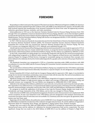
Example 1: Sustained Forces, Moments, and Stresses [Allowable Sh = 130.8 MPa (19.0 ksi)]
Example 1: Displacement Stress Range [Allowable, Eq. (la), SA = 205.2 MPa (29.75 ksi)]
Example 2: Pressure-Temperature Combinations ............................
Example 2: Generic Pipe Stress Model Input: Component Connectivity, Type, and Lengths
Example 2: Results for Operating Case: Reactions on Support and Anchors ..........
Example 2: Sustained Load Condition Listing ...............................
Example 2: Sustained Forces, Moments, and Stresses for Sustained Condition 3 With Node
50's Y+ Support Inactive [Allowable Sh = 127 MPa (18.4 ksi): Fails] .............
Example 3: Pressure-Temperature Combinations ............................
Example 3: Generic Pipe Stress Model Input: Component Connectivity, Type, and Lengths
Example 3: Operating Case 1: Displacement Stress Range [Eq. (lb) Allowable SA
= 364 MPa
(52.7 ksi): Passes] .................................................
Example 3: Operating Case 2: Displacement Stress Range [Eq. (lb) Allowable SA
= 364 MPa
(52.7 ksi): Passes] .................................................
Example 3: Moment Reversal Load Combination Considering Operating Cases 1 and 2, Total
Strain Based: Displacement Stress Range [Eq. (lb) Allowable SA = 364 MPa (52.7 ksi):
Fails] ..........................................................
Gamma Function Evaluation ............................................
Fatigue Material Coefficients (-3cr) .......................................
Fatigue Material Coefficients (-2cr) .......................................
Optional Fatigue Material Coefficients When Ne; > 107
• • • • • • • • • • • • • • • • • • • • • • • • •
Environmental Fatigue Factors for Carbon Steel Piping, T � 93°
C (200°
F) ...........
xiii
506
507
508
509
509
510
511
512
513
514
515
516
521
522
522
523
523
530
546](https://image.slidesharecdn.com/26162943-231229160810-282cb07a/85/ASME-B31-3-2022-Procces-piping-code-for-b31-3-14-320.jpg)
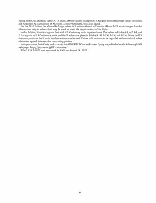
![ASME 831.3-2022
Chapter I
Scope and Definitions
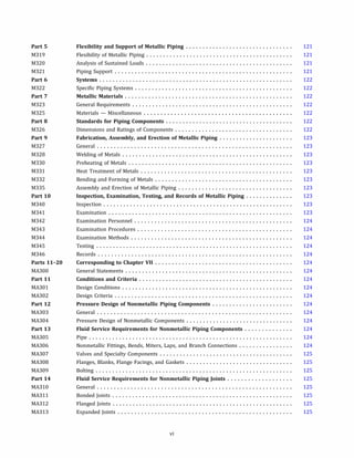
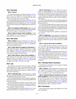
(22) 300 GENERAL STATEMENTS
(a) Identification This Process Piping Code is a Section
of The American Society of Mechanical Engineers Code for
Pressure Piping, ASME 831, an American National Stan
dard. It is published as a separate document for conve
nience of Code users.
(b) Responsibilities
(1) Owner. The owner of a piping installation shall
have overall responsibility for compliance with this
Code, and for establishing the requirements for design
andconstructionthat will govern the entire fluidhandling
or process installation of which the piping is a part. The
owner is also responsible for designating piping in Cate
gory D, Category M, High Pressure, and High Purity Fluid
Services, and fordeterminingifaspecific Quality Systemis
to be employed. [See (d)(4) through (d)(7) and Appendix
Q.] Where applicable, the owner shall consider require
ments imposed by the authority having jurisdiction
regarding the piping installation. The owner may desig
nate a representative tocarry out selected responsibilities
required by this Code, but the owner retains ultimate
responsibility for the actions of the representative.
(2) Designer. The designer is responsible to the
owner for assurance that the engineering design of
piping complies with the requirements of this Code
and with any additional requirements established by
the owner.
(3) Manufacturer, Fabricator, and Erector. The
manufacturer, fabricator, and erector of piping are
responsible for providing materials, components, and
workmanship in compliance with the requirements of
this Code and of the engineering design.
(4) Owner's Inspector. The owner's Inspector (see
para. 340) is responsible to the owner for ensuring
that the requirements of this Code for inspection, exam
ination, andtesting are met. If a Quality System is specified
by the owner to be employed, the owner's Inspector is
responsible for verifying that it is implemented.
(c) Intent of the Code
(1) !tistheintentofthis Codetoset forthengineering
requirements deemed necessary for safe design and
construction of piping installations.
(2) This Code is not intended to apply to the opera
tion, examination, inspection, testing, maintenance, or
repair of piping that has been placed in service. See
para. F300.1 for examples of standards that may apply
1
in these situations. The provisions of this Code may
optionally be applied for those purposes, although
other considerations may also be necessary.
(3) The Code generally specifies a simplified
approach for many of its requirements. A designer
may choose to use a more rigorous analysis to develop
design, materials, fabrication, assembly, erection, exami
nation, and testing requirements. When the designer
decides to take this approach, the designer shall
provide to the owner details and calculations demon
strating that the proposed design, materials, fabrication,
assembly, erection, examination, and testing require
ments are consistent with the criteria of this Code,
including the design criteria described in para. 302.
These details shall be adequate for the owner to verify
the validity of the approach. The approach may be imple
mented following approval by the owner. The details and
calculations shall be documented in the engineering
design.
(4) Piping elements shall conform to the specifica
tions and standards listed in this Code or, if not prohibited
by this Code, shall be qualified for use as set forth in ap
plicable Chapters of this Code.
(SJ The engineering design shall specify any unusual
requirements for a particular service. Where service re
quirements necessitate measures beyond those required
by this Code, such measures shall be specified by the engi
neering design. Where so specified, the Code requires that
they be accomplished.
(6) Compatibility of materials with the service and
hazardsfrominstability ofcontained fluids are not within
the scope of this Code. See para. F323.
(d) Determining Code Requirements
(1) Code requirements for design and construction
include fluid service requirements, which affect selection
andapplication ofmaterials, components, andjoints. Fluid
service requirements include prohibitions, limitations,
and conditions, such as temperature limits or a require
ment for safeguarding (see Appendix G). Code require
ments for a piping system are the most restrictive of
those that apply to any of its elements.
(2) For metallic piping not designated by the owner
as Category M, High Pressure, or High Purity Fluid Service
(see para. 300.2 and Appendix M), Code requirements are
found in Chapters I through VI (the base Code) and fluid
service requirements are found in](https://image.slidesharecdn.com/26162943-231229160810-282cb07a/85/ASME-B31-3-2022-Procces-piping-code-for-b31-3-28-320.jpg)
![ASME 831.3-2022
(-aJ Chapter III for materials
(-bJ Chapter II, Part 3, for components
(-cJ Chapter II, Part 4, for joints
(3J For nonmetallic piping and piping lined with
nonmetals, all requirements are found in Chapter VII.
Paragraph designations begin with "A."
(4J For piping in a fluid service designated as Cate
gory M, all requirements are found in Chapter VIII. Para
graph designations begin with "M."
(SJ For piping in a fluid service designated as Cate
gory D, piping elements restricted to Category D Fluid
Service in Chapters I through VII, as well as elements
suitable for other fluid services, may be used.
(6J For piping designated as High Pressure Fluid
Service, all requirements are found in Chapter IX.
These rules apply only when specifiedby the owner. Para
graph designations begin with "K."
(7J For piping designated as High Purity Fluid
Service, all requirements are found in Chapter X. Para
graph designations begin with "U."
(BJ Requirements for Normal Fluid Service in
Chapters I through VI are applicable under severe
cyclic conditions unless alternative requirements for
severe cyclic conditions are stated.
(9J Requirements for Normal Fluid Service in
Chapters I through VI are applicable for Elevated
Temperature Fluid Service unless alternative require
ments for Elevated Temperature Fluid Service are
invoked.
(eJ Appendices. Appendices of this Code contain Code
requirements,supplementaryguidance, or other informa
tion. See para. 300.4 for a description of the status of each
Appendix.
(fJ Code Cases. ASME issues Code Cases that are appli
cable to this Code. The Code Cases
(lJ modify the requirements of this Code
(2J are applicable from the issue date until the Cases
are annulled
(3J may be used only when approved by the owner.
When so approved, the Code Cases shallbe specified in the
engineeringdesignandbecomerequirementsofthisCode.
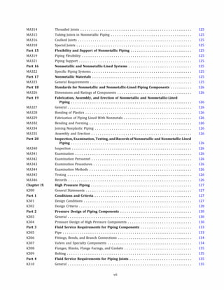
300.1 Scope
Rules for the Process Piping Code Section 831.31
have
been developed considering piping typically found in
petroleum refineries; onshore and offshore petroleum
and natural gas production facilities; chemical, pharma
ceutical, textile, paper, oreprocessing, semiconductor, and
cryogenic plants; food and beverage processing facilities;
and related processing plants and terminals.
1 831 references here and elsewhere in this Code are to the ASME 831
Code for Pressure Piping and its various Sections, which are identified
and briefly described in the Introduction.
2
300.1.1 Content and Coverage
(aJ This Code prescribes requirements for materials
and components, design, fabrication, assembly, erection,
examination, inspection, and testing of piping.
(bJ This Code applies to piping for all fluids, including
(lJ raw, intermediate, and finished chemicals
(2J petroleum products
(3J gas, steam, air, and water
(4J fluidized solids
(SJ refrigerants
(6J cryogenic fluids
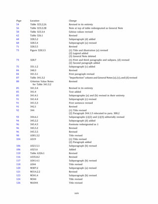
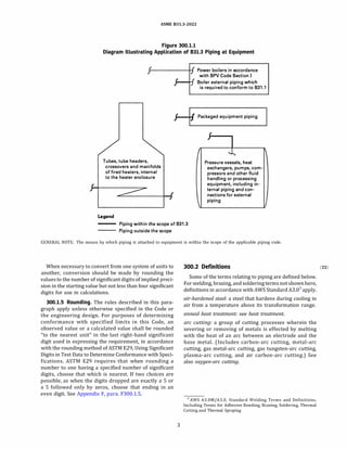
(cJ See Figure 300.1.1 for a diagram illustrating the
application of 831.3 piping at equipment. The joint
connecting piping to equipment is within the scope of
831.3.
300.1.2 Packaged Equipment Piping. Also included
within the scope of this Code is piping that interconnects
pieces or stages within a packaged equipment assembly.
300.1.3 Exclusions. This Code excludes the following:
(aJ piping systems designed for internal gage pres
sures at or above zero but less than 105 kPa (15 psi),
provided the fluid handled is nonflammable, nontoxic,
and not damaging to human tissues as defined in
300.2, and its design temperature is from -29°
C
(-20°
F) through 186°
C (366°
F)
(bJ power boilers in accordance with ASME 8PVC,2
Section I and boiler external piping that is required to
conform to ASME 831.1
(cJ tubes, tube headers, crossovers, and manifolds of
fired heaters that are internal to the heater enclosure
(dJ pressure vessels, heat exchangers, pumps,
compressors, and other fluid handling or processing
equipment, including internal piping and connections
for external piping
300.1.4 Units of Measure. This Code states values in
both SI and U.S. Customary units. Within the text, the U.S.
Customary units are shown in parentheses or in separate
tables. The values stated in each system are not exact
equivalents; therefore, each system of units should be
used independently of the other.
When separate equations are provided for SI and U.S.
Customary units, those equations shall be executed using
variablesintheunitsassociated with thespecificequation.
The results obtained from execution of these equations
may be converted to other units.
2 ASME BPVC references here and elsewhere in this Code are to the
ASME Boiler and Pressure Vessel Code and its various Sections as
follows:
Section I, Rules for Construction of Power Boilers
Section II, Materials, Parts C and D
Section Ill, Rules for Construction of Nuclear Facility Components,
Division 1, Subsection NH
Section V, Nondestructive Examination
Section Vil], Rules for Construction of Pressure Vessels, Divisions 1, 2,
and 3
Section IX, Welding, Brazing, and Fusing Qualifications](https://image.slidesharecdn.com/26162943-231229160810-282cb07a/85/ASME-B31-3-2022-Procces-piping-code-for-b31-3-29-320.jpg)
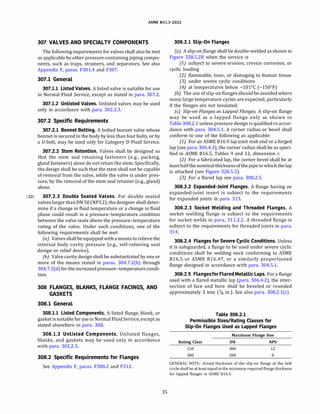
![ASME 831.3-2022
arc welding (AW): a group of welding processes that
produces coalescence of metals by heating them with
an arc or arcs, with or without the application of pressure
and with or without the use of filler metal.
assembly: the joining together of two or more piping
components by bolting, welding, bonding, screwing,
brazing, soldering, cementing, or use of packing
devices as specified by the engineering design.
autogenous weld: a weld made by fusion of the base metal
without the addition of filler metal [see also gas tungsten
arc welding (GTA W)].
automaticwelding: weldingwithequipment thatperforms
the welding operation without adjustment of the controls
by an operator. The equipment may or may not perform
the loading and unloading of the work.
backing filler metal: see consumable insert.
backing ring: material in the form of a ring used to support
molten weld metal.
balanced piping system: see para. 319.2.2(a).
base material: the material to be brazed, soldered, welded,
or otherwise fused.
basic allowable stress: see stress terms frequently used.
bolt design stress: see stress terms frequently used.
bonded joint: a permanent joint in nonmetallic piping
made by one of the following methods:
(a) adhesivejoint: a joint made by applying an adhesive
to the surfaces to be joined and pressing them together
(b) butt-and-wrapped joint: a joint made by butting
together the joining surfaces and wrapping the joint
with plies of reinforcing fabric saturated with resin
(c) heat fusion joint: a joint made by heating the
surfaces to be joined and pressing them together to
achieve fusion
(d) hot gas weldedjoint: a joint made by simultaneously
heatingthe surfacestobejoinedand a filler materialwitha
stream of hot air or hot inert gas, then pressing the
surfaces together and applying the filler material to
achieve fusion
(e) solvent cemented joint: a joint made by using a
solvent cement to soften the surfaces to be joined and
pressing them together
(!) e/ectrofusion joint: a joint made by heating the
surfaces to be joined using an electrical resistance wire
coil that remains embedded in the joint.
bonder: one who performs a manual or semiautomatic
bonding operation.
bonding operator: one whooperatesmachine orautomatic
bonding equipment.
bonding procedure: the detailed methods and practices
involved in the production of a bonded joint.
4
bonding procedure specification (BPS): the document that
lists the parameters to be used in the construction of
bonded joints in accordance with the requirements of
this Code.
borescopic examination: a visual examination aided by a
mechanical or electromechanical device to examine the
inside diameter of inaccessible welds.
branch connectionfitting: an integrally reinforced fitting
welded to a run pipe and connected to a branch pipe by a
buttwelding, socket welding, threaded, or flanged joint;
includes a branch outlet fitting conforming to MSS SP-97.
brazing: a metal joining process wherein coalescence is
produced by use of a nonferrous filler metal having a
melting point above 427°
C (800°
F), but lower than
that of the base metals being joined. The filler metal is
distributed between the closely fitted surfaces of the
joint by capillary attraction.
buttjoint: a joint between two members aligned approxi
mately in the same plane.
Category D: see fluid service.
Category M: see fluid service.
caulkedjoint: a joint in which suitable material (or mate
rials) is either poured or compressed by the use of tools
into the annular space between a bell (or hub) and spigot
(or plain end), thus comprising the joint seal.
chemical plant: an industrial plant for the manufacture or
processing of chemicals, or of raw materials or intermedi
ates for such chemicals. A chemical plant may include
supporting and service facilities, such as storage,
utility, and waste treatment units.
cold spring: see para. 319.2.4.
compression type tubefittings: tube fittings consisting of a
flareless, mechanical grip connection, including a body,
nut, and single or dual ferrules. See also para. 0306.6.
connectionsfor external piping: those integral parts of in
dividual pieces of equipment that are designed for attach
ment of external piping.
construction: anall-inclusive termcomprisingfabrication,
assembly, erection, inspection, examination, and testing.
consumable insert: preplaced filler metal that is complete
ly fused into the root of the joint and becomes part of the
weld.
damaging to human tissues: for the purposes of this Code,
this phrase describes a fluid service in which exposure to
the fluid, caused by leakage under expected operating con
ditions, can harm skin, eyes, or exposed mucous
membranes so that irreversible damage may result
unless prompt restorative measures are taken. (Restora
tive measures may include flushing with water, adminis
tration of antidotes, or medication.)
design minimum temperature: see para. 301.3.1.](https://image.slidesharecdn.com/26162943-231229160810-282cb07a/85/ASME-B31-3-2022-Procces-piping-code-for-b31-3-31-320.jpg)
![ASME 831.3-2022
cross section. Forweldsbetween perpendicularmembers,
the definitions in Figure 328.S.2A apply.
NOTE: When the angle between members exceeds 105 deg, size
is of less significance than effective throat (see also throat ofa
fillet weld).
{b) groove weld: the joint penetration (depth of bevel
plus the root penetration when specified). The size of a
groove weld and its effective throat are the same.
slag inclusion: nonmetallic solid material entrapped in
weld metal or between weld metal and base metal.
soldering: a metal joining process wherein coalescence is
produced by heating to suitable temperatures and by
using a nonferrous alloy fusible at temperatures below
427°
C (800°
F) and having a melting point below that
of the base metals being joined. The filler metal is distrib
uted between closely fitted surfaces of the joint by capil
lary attraction. In general, solders are lead-tin alloys and
may contain antimony, bismuth, and other elements.
solution heat treatment: see heat treatment.
stress ratio: see para. 323.2.2(b).
stress relief see heat treatment.
stress terms frequently used:
(a) basic allowable stress: this term, symbol S, repre
sents the stress value for any material determined by
the appropriate stress basis in para. 302.3.2
(b) bolt design stress: this term represents the design
stressused todeterminetherequiredcross-sectional area
of bolts in a bolted joint
(c) hydrostatic design basis: selected properties of
plastic piping materials to be used in accordance with
ASTM 02837 or 02992 to determine the HOS [see (d)
below] for the material
(d) hydrostatic design stress {HDS): the maximum
continuous stress due to internal pressure to be used
inthedesign ofplastic piping, determinedfromthehydro
static design basis by use of a service (design) factor
submerged arc welding {SAW): an arc welding process that
produces coalescence of metals by heating them with an
arc or arcs between a bare metal electrode or electrodes
and the work. The arc is shielded by a blanket of granular,
fusible materialon the work. Pressure isnotused andfiller
metal is obtained from the electrode and sometimes from
a supplemental source (welding rod, flux, or metal gran
ules).
tack weld: a weld made to hold parts of a weldment in
proper alignment until the final welds are made.
tempering: see heat treatment.
thermoplastic: a plastic that is capable of being repeatedly
softened by increase of temperature and hardened by
decrease of temperature.
9
thermosettingresin: a resincapable ofbeing changedinto a
substantially infusible or insoluble product when cured at
room temperature, or by application of heat, or by chem
ical means.
throat of a fillet weld:
(a) theoretical throat: the perpendicular distance from
the hypotenuse of the largest right triangle that can be
inscribed in the weld cross section to the root of the joint
(bJ actual throat: the shortest distance from the root of
a fillet weld to its face
(c) effective throat: the minimum distance, minus any
reinforcement (convexity), between the weld root and the
face of a fillet weld
toe ofweld: the junction between the face of a weld and the
base material.
tube: see pipe.
tungsten electrode: a nonfiller-metal electrode used in arc
welding or cutting, made principally of tungsten.
unbalanced piping system: see para. 319.2.2(b).
undercut: a groove melted into the base material adjacent
to the toe or root of a weld and left unfilled by weld mate
rial.
visual examination: see para. 344.2.1.
weld: a localized coalescence of material wherein coales
cence is produced either by heating to suitable tempera
tures, with or without the application of pressure, or by
application of pressure alone, and with or without the use
of filler material.
weldcoupon: asample weldusedtodetermine weld accep
tance. Types of weld coupons are defined as follows:
(a) primary weld coupon: made prior to the start of
production welding to establish a benchmark of weld
acceptance
(b) production weld coupon: made when any of the con
ditionsinpara. 0341.4.S exist andusedtocompare against
a corresponding primary weld coupon to demonstrate
continued acceptability of welds during production
welding
weld coupon examination: see para. 0344.8.1.
weld reinforcement: weld material in excess of the speci
fied weld size.
welder: one who performs a manual or semi-automatic
welding operation. (This term is sometimes erroneously
used to denote a welding machine.)
weldingoperator: one who operates machine or automatic
welding equipment.
welding procedure: the detailed methods and practices
involved in the production of a weldment.
welding procedure specification (WPS): the document that
lists the parameters to be used in construction of weld
ments in accordance with requirements of this Code.](https://image.slidesharecdn.com/26162943-231229160810-282cb07a/85/ASME-B31-3-2022-Procces-piping-code-for-b31-3-36-320.jpg)
![ASME 831.3-2022
300.4 Status of Appendices
weldment: anassemblywhosecomponentpartsarejoined
by welding.
300.3 Nomenclature
Dimensional and mathematical symbols used in this
CodearelistedinAppendixJ, with definitionsand location
references to each. Uppercase and lowercase English
lettersarelisted alphabetically, followed by Greek letters.
Table 300.4 indicates for each Appendix of this Code
whether it contains Code requirements, guidance, or
supplemental information. See the first page of each
Appendix for details.
NOTES:
Appendix
A
B
c
E
F
G
H
K
L
M
N
Q
R
s
v
w
x
z
Table 300.4
Status of Appendices in ASME 831.3
Title
Allowable Stresses and Quality Factors for Metallic Piping and Bolting Materials
Stress Tables and Allowable Pressure Tables for Nonmetals
Physical Properties of Piping Materials
Reference Standards
Guidance and Precautionary Considerations
Safeguarding
Sample Calculations for Branch Reinforcement
Nomenclature
Allowable Stresses for High Pressure Piping
Aluminum Alloy Pipe Flanges
Guide to Classifying Fluid Services
Application of ASME 831.3 Internationally
Quality System Program
Use of Alternative Ultrasonic Acceptance Criteria
Piping System Stress Analysis Examples
Allowable Variations in Elevated Temperature Service
High-Cycle Fatigue Assessment of Piping Systems
Metallic Bellows Expansion Joints
Preparation of Technical Inquiries
(1) Contains default requirements, to be used unless more directly applicable data are available.
(2) Contains no requirements but Code user is responsible for considering applicable items.
(3) Contains requirements applicable only when use of Chapter IX is specified.
Status
Requirements
Requirements
Requirements (Note (1)]
Requirements
Guidance [Note (2)]
Guidance [Note (2)]
Guidance
Information
Requirements (Note (3)]
Specification [Note (4)]
Guidance [Note (2)]
Guidance [Note (2)]
Guidance (Note (2)]
Requirements [Note (5)]
Guidance [Note (2)]
Guidance [Note (2)]
Requirements
Requirements
Requirements (Note (5)]
(4) Contains pressure-temperature ratings, materials, dimensions, and markings of forged aluminum alloy flanges.
(5) Contains administrative requirements.
10](https://image.slidesharecdn.com/26162943-231229160810-282cb07a/85/ASME-B31-3-2022-Procces-piping-code-for-b31-3-37-320.jpg)
![ASME 831.3-2022
Chapter II
Design
PART 1
CONDITIONS AND CRITERIA
301 DESIGN CONDITIONS
Paragraph 301 states the qualifications of the Designer,
definesthe temperatures, pressures, and forcesapplicable
to the design of piping, and states the consideration that
shall be given to various effects andtheirconsequent load
ings. See also Appendix F, para. F301.
301.1 Qualifications of the Designer
The Designer is the person(s) in charge of the engi
neeringdesignofapipingsystemandshallbe experienced
in the use of this Code. The qualifications and experience
required of the Designer will depend on the complexity
and criticality of the system and the nature of the indiv
idual's experience.The owner's approval is required ifthe
individual does not meet at least one of the following
criteria:
(a) Completion of a degree, accredited by an indepen
dent agency [such as ABET (U.S. and international), NBA
(India), CTI (France), and CNAP (Chile)], in engineering,
science, or technology, requiring the equivalent of at least
4 yr of full-time study that provides exposure to funda
mental subject matter relevant to the design of piping
systems, plus a minimum of 5 yr of experience in the
design of related pressure piping.
{b) Professional Engineering registration, recognized
by the local jurisdiction, and experience in the design
of related pressure piping.
(c) Completion ofan accredited engineering technician
or associates degree, requiring the equivalent of at least 2
yr of study, plus a minimum of 10 yr of experience in the
design of related pressure piping.
(d) Fifteen yr of experience in the design of related
pressure piping.
Experience in the design of related pressure piping is
satisfied by piping design experience that includes design
calculations for pressure, sustained and occasional loads,
and piping flexibility.
11
301.2 Design Pressure
301.2.1 General
(a) The design pressure of each component in a piping
system shall be not less than the pressure at the most
severe condition of coincident internal or external pres
sure and temperature (minimum or maximum) expected
during service, except as provided in para. 302.2.4.
{b) The most severe condition is that which results in
the greatest required component thickness and the
highest component rating.
(c) When more than one set of pressure-temperature
conditions exist for a piping system, the conditions
governing the rating of components conforming to
listed standardsmay differ fromtheconditions governing
the rating of components designed in accordance with
para. 304.
{d) When a pipe is separated into individualized pres
sure-containing chambers (including jacketed piping,
blanks, etc.), the partition wall shall be designed on
the basis of the most severe coincident temperature
(minimum or maximum) and differential pressure
between the adjoining chambers expected during
service, except as provided in para. 302.2.4.
301.2.2 Required Pressure Containment or Relief
(a) Provision shall be made to safely contain or relieve
(see para. 322.6.3) any expected pressure to which the
piping may be subjected. Piping not protected by a pres
sure-relieving device, or that can be isolated from a pres
sure-relieving device, shall be designed for at least the
highest expected pressure.
(b) Sources of pressure to be considered include
ambient influences, pressure oscillations and surges,
improper operation, decomposition of unstable fluids,
static head, and failure of control devices.
(c) The allowances of para. 302.2.4(f) are permitted,
provided that the other requirements of para. 302.2.4
are also met.
301.3 Design Temperature
The design temperature of each component in a piping
system is the temperature at which, under the coincident
pressure, the greatest thickness or highest component
rating is required in accordance with para. 301.2. (To
satisfy the requirements of para. 301.2, different](https://image.slidesharecdn.com/26162943-231229160810-282cb07a/85/ASME-B31-3-2022-Procces-piping-code-for-b31-3-38-320.jpg)
![ASME 831.3-2022
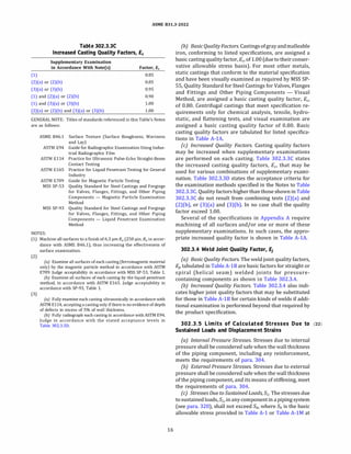
(22) 302.3.2 Bases for Design Stresses.2
The bases for
establishing design stress values for bolting materials
and basic allowable stressvalues for other metallic mate
rials in this Code are specified in (a) through (d). In the
application of these criteria,the yieldstrengthat tempera
ture is considered to be SyRy and the tensile strength at
temperature is considered to be l.lSTRT, where
RT = ratio of the average temperature-dependent trend
curve value of tensile strength to the room temperature
tensile strength
Ry = ratio of the average temperature-dependent trend
curve value of yield strength to the room temperature
yield strength
ST = specified minimum tensile strength at room
temperature
Sy = specifiedminimumyieldstrengthatroomtempera
ture
(a) Bolting Materials. Design stress values at tempera
ture forboltingmaterialsshallnot exceedthe lowestofthe
following:
(1) at temperatures below the creep range, for
bolting materials whose strength has not been enhanced
by heat treatment or strain hardening, the lowest of one
fourth of ST, one-fourth of tensile strength at temperature,
two-thirds of Sy, and two-thirds of yield strength at
temperature
(2) at temperatures below the creep range, for
bolting materials whose strength has been enhanced
by heat treatment or strain hardening, the lowest of
one-fifth of ST, one-fourth of the tensile strength at
temperature, one-fourth of Sy, and two-thirds of the
yield strength at temperature (unless these values are
lower than corresponding values for annealed material,
in which case the annealed values shall be used)
(3) 100% of the average stress for a creep rate of
0.01% per 1000 h
(4) 67% of the average stress for rupture at the end
of 100000 h
(5) 80% of minimum stress for rupture at the end of
100000 h
(b) Gray Iron. Basicallowablestress values at tempera
ture for gray iron shall not exceed the lower of the
following:
(1) one-tenth of ST
(2) one-tenth of the tensile strength at temperature
2
These bases are the same as those for ASME BPVC, Section Ill, Class 1
materials, given in ASME BPVC, Section II, Part D. Stress values in B31.3,
Appendix A, at temperatures below the creep range generally are the
same as those listed in ASME BPVC, Section II, Part D, Tables 2A and 2B,
and in Table 3 for bolting, corresponding to those bases. They have been
adjusted as necessary to exclude casting quality factors and longitudinal
weld joint quality factors. Stress values at temperatures in the creep
range generally are the same as those in ASME BPVC, Section II, Part
D, Tables lA and lB, corresponding to the bases for ASME BPVC,
Section Vlll, Division 1.
15
(c) Malleable Iron. Basic allowable stress values at
temperature for malleable iron shall not exceed the
lower of the following:
(1) one-fifth of ST
(2) one-fifth of the tensile strength at temperature
(d) Other Materials. Basic allowable stress values at
temperature for materials other than bolting materials,
gray iron, and malleable iron shall not exceed the
lowest of the following:
(1) the lower of one-third of ST and one-third of
tensile strength at temperature.
(2) exceptas provided in (3)below,the lower of two
thirds of Sy and two-thirds of yield strength at tempera
ture.
(3) for austenitic stainless steels and nickel alloys
having similar stress-strain behavior, the lower of
two-thirds of Sy and 90% of yield strength at temperature
[see (e)].
(4) 100% of the average stress for a creep rate of
0.01% per 1000 h.
(5) for temperatures up to and including 815°
(
(1,500°
F), 67% of the average stress for rupture at the
end of 100000 h.
(6) for temperatures higher than 815°
C (1,500°
F),
(100 x Favg)% times the average stress for rupture at
the end of 100 000 h. Favg is determined from the
slope, n, of the log time-to-rupture versus log stress
plot at 100 000 h such that log Favg
= l/n. Favg
shall
not exceed 0.67.
(7) 80% ofthe minimumstress forrupture atthe end
of 100000 h.
For structural grade materials, the basic allowable
stress shall be 0.92 times the lowest value determined
in (1) through (7).
(e) Application Limits. Application of stress values
determined in accordance with (d)(3) is not recommend
ed for flangedjoints and other components in whichslight
deformation can cause leakage or malfunction.
(1) These values are shown in italics or boldface in
Table A-1, as explained in Note (2a) in Appendix A, Notes
for Tables A-1 and A-lM. Instead, either 75% of the stress
value in Table A-1 or two-thirds of the yield strength at
temperature listed in ASME BPVC, Section II, Part D, Table
Y-1 should be used.
(2) Stress values determined in accordance with
(d)(3) are not identified in Table A-lM. See Note (2b)
in Appendix A, Notes for Tables A-1 and A-lM.. When
using Table A-lM, two-thirds of the yield strength at
temperature listed in ASME BPVC, Section II, Part D,
Table Y-1 should be used.
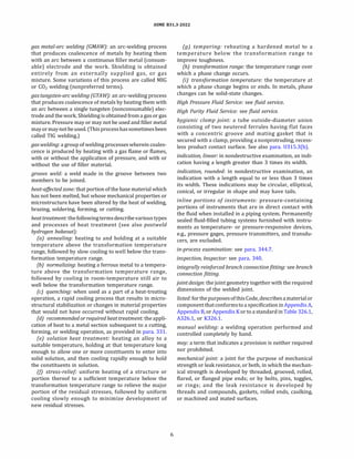
302.3.3 Casting Quality Factor, Ee
(a) General. The casting quality factors, E0 defined
hereinshallbe used forcast components not having pres
sure-temperature ratings established by standards in
Table 326.1.](https://image.slidesharecdn.com/26162943-231229160810-282cb07a/85/ASME-B31-3-2022-Procces-piping-code-for-b31-3-42-320.jpg)

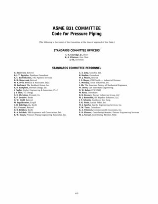
![ASME 831.3-2022
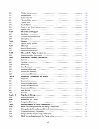
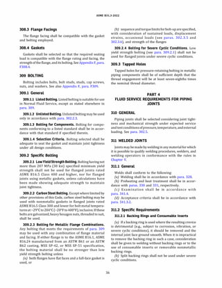
Table 302.3.4
Longitudinal Weld Joint Quality Factor, Ei
Factor,
No. Type of Joint Type of Seam Examination E;
1 Furnace butt weld, Straight As required by listed specification 0.60
continuous weld
�
[Note (1)]
2 Electric resistance Straight or spiral (helical seam) As required by listed specification 0.85
weld
�
[Note (1)]
3 Electric fusion weld
(a) Single butt weld Straight or spiral (helical seam) As required by listed specification or 0.80
this Code
(with or without filler
�
Additionally spot radiographed in 0.90
metal) accordance with para. 341.5.1
Additionally 100% radiographed in 1.00
accordance with para. 344.5.1 and
Table 341.3.2
(b) Double butt weld Straight or spiral (helical seam) As required by listed specification 0.85
(except as provided in4 below) or this Code
(with or without filler
�
Additionally spot radiographed in 0.90
metal) accordance with para. 341.5.1
Additionally 100% radiographed in 1.00
accordance with para. 344.5.1 and
Table 341.3.2
4 Specific specification
AP! SL, electric fusion Straight (with one or two As required by specification 0.95
weld, double butt
�
seams) or spiral (helical seam) Additionally 100% radiographed in 1.00
seam accordance with para. 344.5.1
and Table 341.3.2
NOTE: (1) It is not permitted to increase the joint quality factor by additional examination for joint 1 or 2.
displacementstress range requirements ofthis paragraph
and of para. 319. A significant stress cycle is defined in
para. W300. When the alternative rules of Appendix W
are applied, the calculations shall be documented in
the engineering design.
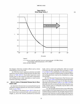
(e) WeldjointStrength Reduction Factor, W. At elevated
temperatures, the long-term strength of weld joints may
be lower than the long-term strength of the base material.
The weld joint strength reduction factor, W, is the ratio
ofthe nominal stress to cause failure ofa weld joint to that
of the corresponding base material for an elevated
temperature condition of the same duration. It only
applies at weld locations in longitudinal or spiral
(helical seam) welded piping components. The designer
is responsible for the application of weld joint strength
reduction factors to other welds (e.g., circumferential).
When determining the required wall thickness for
internal pressure in accordance with para. 304, for
each coincident operating pressure-temperature condi
tion under consideration, the product of the basic allow
able stress and the applicable weld quality factor,SE, shall
be multiplied by W.
18
Wis equal to 1.0 when evaluating occasional loads, e.g.,
wind and earthquake, or when evaluating permissible
variations in accordance with para. 302.2.4. Application
of Wis notrequiredwhen determiningthe pressurerating
for the occasional load or permissible variation condition.
It is also not required when calculating the allowable
stress range for displacement stresses, SA, in (d).
For other than occasional loads or permissible varia
tions, W shall be in accordance with Table 302.3.S
except as provided in (f).
(/) Alternative WeldjointStrength Reduction Factors. A
weld joint strength reduction factor other than that listed
in Table302.3.Smaybe used in accordancewith one ofthe
following criteria:
(1) Creep test data may be used to determine the
weld joint strength reduction factor, W. However, the
use of creep test data to increase the factor W above
that shown in Table 302.3.S is not permitted for the
CrMo and Creep Strength Enhanced Ferritic (CSEF)
steels materials, as defined in Table 302.3.S. Creep
testing of weld joints to determine weld joint strength
reduction factors, when permitted, should be full thick
ness cross-weld specimens with test durations of at
least 1 000 h. Full thickness tests shall be used unless](https://image.slidesharecdn.com/26162943-231229160810-282cb07a/85/ASME-B31-3-2022-Procces-piping-code-for-b31-3-45-320.jpg)
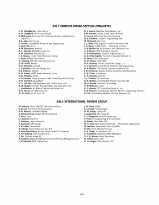
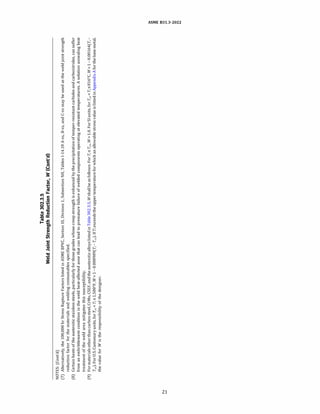
![(22)
N
0
Steel
Group
Carbon
Steel
Cr
Mo
[Notes
(1)-(3)]
CSEF
(N
+
T)
[Notes
(3)-(5)]
CSEF
[Notes
(3),
(4)]
(Subcritical
PWHT)
Autogenous
welds
in
austenitic
stainless
grade
3xx,
and
N088xx
and
N066xx
nickel
alloys
[Note
(6)]
Austenitic
stainless
grade
3xx
and
N088xx
nickel
alloys
[Notes
(7),
(8)]
Other
materials
[Note
(9)]
GENERAL
NOTES:
S427
(
S800)
1
1
454
(850)
1
0.95
482
(900)
1
0.91
1
Table
302.3.5
Weld
Joint
Strength
Reduction
Factor,
W
Component
Temperature,
T;,
°
C
(
°
F)
510
538
566
593
621
649
677
(950)
(
1,000)
(
1,050)
(
1,100)
(
1,150)
(
1,200)
(
1,250)
1
1
1
1
0.86
0.82
0.77
0.73
0.68
0.64
1
0.95
0.91
0.86
0.82
0.77
0.5
0.5
0.5
0.5
0.5
0.5
1
1
1
1
1
1
1
1
0.95
0.91
0.86
0.82
0.77
0.73
704
732
760
788
816
(
1,300)
(
1,350)
(
1,400)
(
1,450)
(
1,500)
1
1
1
1
1
0.68
0.64
0.59
0.55
0.5
(a)
Weld
joint
strength
reduction
factors
at
temperatures
above
the
upper
temperature
limit
listed
in
Appendix
A
for
the
base
metal
or
outside
of
the
applicable
range
in
Table
302.3.5
are
the
responsibility
of
the
designer.
At
temperatures
below
those
where
weld
joint
strength
reduction
factors
are
tabulated,
a
value
of
1.0
shall
be
used
for
the
factor
W
where
required;
however,
the
additional
rules
of
this
Table
and
Notes
do
not
apply.
(b)
T
cr
=
temperature
25
°
C
(50
°
F)
below
the
temperature
identifying
the
start
of
time-dependent
properties
listed
under
"NOTES
-
TIME-DEPENDENT
PROPERTIES"
(Txx)
in
the
Notes
to
ASME
BPVC,
Section
II,
Part
D,
Tables
lA
and
18
for
the
base
metals
joined
by
welding.
For
materials
not
listed
in
Section
II,
Part
D,
T
c
rshall
be
the
temperature
where
the
creep
rate
or
stress
rupture
criteria
in
paras.
302.3.2(d)(
4)
through
302.3.2(d)(7)
governs
the
basic
allowable
stress
value
of
the
metals
joined
by
welding.
When
the
base
metals
differ,
the
lower
value
of
T
cr
shall
be
used
for
the
weld
joint.
(c)
T;
=
temperature,
°
C
(
°
F),
of
the
component
for
the
coincident
operating
pressure-temperature
condition,
i,
under
consideration.
(d)
CAUTIONARY
NOTE:
There
are
many
factors
that
may
affect
the
life
of
a
welded
joint
at
elevated
temperature
and
all
of
those
factors
cannot
be
addressed
in
a
table
of
weld
joint
strength
reduction
factors.
For
example,
fabrication
issues
such
as
the
deviation
from
a
true
circular
form
in
pipe
(e.g.,
"peaking"
at
longitudinal
weld
seams)
or
offset
at
the
weld
joint
can
cause
an
increase
in
stress
that
may
result
in
reduced
service
life
and
control
of
these
deviations
is
recommended.
(
e)
The
weld
joint
strength
reduction
factor,
W,
may
be
determined
using
linear
interpolation
for
intermediate
temperature
values.
NOTES:
(1)
The
Cr-Mo
steels
include
1
/
2
Cr-
%
Mo,
lCr-
1
/iMo,
1
%
Cr-
%
Mo-Si,
2
%
Cr-1Mo,
3Cr-1Mo,
5Cr-
1
/
2
Mo,
and
9Cr-1Mo.
Longitudinal
and
spiral
(helical
seam)
welds
shall
be
normalized,
normalized
and
tempered,
or
subjected
to
proper
subcritical
postweld
heat
treatment
(PWHT)
for
the
alloy.
Required
examination
is
in
accordance
with
para.
341.4.4
or
para.
305.2.4.
(2)
Longitudinal
and
spiral
(helical
seam)
seam
fusion
welded
piping
components
are
not
permitted
for
C-
1
/
2
Mo
steel
above
454
°
C
(850
°
F).
(3)
The
required
carbon
content
of
the
weld
filler
metal
shall
be
�0.05
C
wt.%.
See
para.
341.4.4(b)
for
examination
requirements.
The
basicity
index
of
SAW
flux
shall
be
�1.0.
(4)
The
CSEF
(Creep
Strength
Enhanced
Ferritic)
steels
include
2
1
/
4
Cr-l.6W-V-Cb,
9Cr-1Mo-V,
9Cr-1Mo-1W-Cb,
9Cr-2W,
and
12Cr-2W.
(5)
N
+
T
=
Normalizing
+
Tempering
PWHT.
(6)
Autogenous
welds
without
filler
metal
in
austenitic
stainless
steel
(grade
3xx)
and
austenitic
nickel
alloys
UNS
Nos.
N066xx
and
N088xx.
A
solution
anneal
after
welding
is
required
for
use
of
the
factors
in
the
Table.
See
para.
341.4.3(b)
for
examination
requirements.
>
"'
!:Tl
0::,
w
......
w
N
0
N
N](https://image.slidesharecdn.com/26162943-231229160810-282cb07a/85/ASME-B31-3-2022-Procces-piping-code-for-b31-3-47-320.jpg)
![ASME 831.3-2022
Table 304.1.1
Values of Coefficient Y for t < D/6
482 (900) 510 538
Material and Below (950) (1,000)
Ferritic steels
Austenitic steels
Nickel alloys
0.4 0.5 0.7
0.4 0.4 0.4
0.4 0.4 0.4
UNS Nos. N06617,
N08800, N08810,
and N08825
Gray iron
Other ductile metals
0.0
0.4 0.4 0.4
304.1.2 Straight Pipe Under Internal Pressure
(a) Fort< D/6, the internal pressure design thickness
for straight pipe shall be not less than that calculated in
accordance with either eq. (3a) or eq. (3b)
PD
t= Daj
2(SEW + PY)
P(d + 2c)
t=-------
2[SEW - P(l - Y)]
(3b)
(b) Fort� D/6 or for P/SE > 0.385, calculation of pres
sure design thickness for straight pipe requires special
consideration of factors such as theory of failure,
effects of fatigue, and thermal stress.
304.1.3 Straight Pipe Under External Pressure. To
determine wall thickness and stiffening requirements
for straight pipe under external pressure, the procedure
outlined in ASME BPVC, Section VIII, Division 1, UG-28
through UG-30 shall be followed, using as the design
length, L, the running centerline length between any
two sections stiffened in accordance with UG-29. As an
exception, for pipe with D0/t < 10, the value of S to be
used in determining P02 shall be the lesser of the following
values for pipe material at design temperature:
(a) 1.5 times the stress value from Table A-1 or Table
A-lM of this Code, or
(b) 0.9 times the yield strength tabulated in ASME
BPVC, Section II, Part D, Table Y-1 for materials listed
therein
(ThesymbolD0 inASME BPVC,SectionVIII is equivalent
to D in this Code.)
304.2 Curved and Mitered Segments of Pipe
304.2.1 Pipe Bends. The minimum required thickness,
t
m, of a bend, after bending, in its finished form, shall be
determined in accordance with eqs. (2) and (3c)
23
Temperature, °
C (°
F)
566
(1,050)
0.7
0.4
0.4
0.4
593 621 649
(1,100) (1,150) (1,200)
0.7 0.7 0.7
0.5 0.7 0.7
0.4 0.4 0.5
0.4 0.4 0.4
PD
t=-------
2[(SEW/I) + PY]
where at the intrados (inside bend radius)
4(R1/D) - 1
J=-----
4(R1/D) - 2
and at the extrados (outside bend radius)
I = _4
_
(R
_
1/
_
D
_
)
_
+_1
4(R1/D)+ 2
677 (1,250)
and Above
0.7
0.7
0.7
0.4
(3c)
(3d)
(3e)
and at the sidewall on the bend centerline radius, I= 1.0,
and where
R1 = bend radius of welding elbow or pipe bend
Thickness variations from the intrados to the extrados
and along the length of the bend shall be gradual. The
thickness requirements apply at the mid-span of the
bend, y/2, at the intrados, extrados, and bend centerline
radius. The minimum thickness at the end tangents shall
not be less than the requirements of para. 304.1 for
straight pipe (see Figure 304.2.1).
304.2.2 Elbows. Manufactured elbows not in accor
dance with para. 303 shall be qualified as required by
para. 304.7.2 or designed in accordance with para.
304.2.1, except as provided in para. 328.4.2(b)(6).
304.2.3 Miter Bends. An angular offset of 3 deg or less
(angle ain Figure 304.2.3) does not require design consid
eration as a miter bend. Acceptable methods for pressure
design of multiple and single miter bends are given in (a)
and (b) below.
(a) Multiple Miter Bends. The maximum allowable
internal pressure shall be the lesser value calculated
from eqs. (4a) and (4b). These equations are not applica
ble when e exceeds 22.5 deg.](https://image.slidesharecdn.com/26162943-231229160810-282cb07a/85/ASME-B31-3-2022-Procces-piping-code-for-b31-3-50-320.jpg)
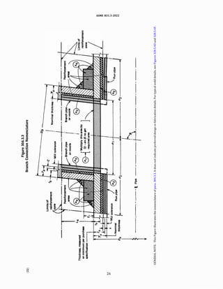
![ASME 831.3-2022
Figure 304.2.1
Nomenclature for Pipe Bends
I
I
I
I
I
I
: R,
lntrados
�
I
I
I
Figure 304.2.3
Nomenclature for Miter Bends
SEW(T - c)
(
T - c
l
� =
�aj
r2 (T-c) + 0.643tane�r2(T-c)
(4b)
(b) Single Miter Bends
(1) The maximum allowable internal pressure for a
single miter bend with angle(} not greater than 22.5 deg
shall be calculated by eq. (4a).
(2) The maximum allowable internal pressure for a
single miter bend with angle(} greater than 22.5 deg shall
be calculated by eq. (4c)
24
SEW(T - c)
(
T - c
l
�= �0
r2 (T- c) + l.2Stane�r2(T-c)
(c) The miter pipe wall thickness, T, used in eqs. (4a),
(4b), and (4c) shall extend a distance not less than M from
the inside crotch of the end miter welds where
M = the larger of 2.5(r2 7)0
·
5
or tan(} (R1 - r2)
The length of taper at the end of the miter pipe may be
included in the distance, M.
(d) The following nomenclature is used in eqs. (4a),
(4b), and (4c) for the pressure design of miter bends:
c = same as defined in para. 304.1.1
E = same as defined in para. 304.1.1
Pm maximum allowable internal pressure for miter
bends
R1 effective radius of miter bend, defined as the
shortest distance from the pipe centerline to
the intersection of the planes of adjacent
miter joints
r2 = mean radius of pipe using nominal wall 'f
S = same as defined in para. 304.1.1
T = miterpipewallthickness(measuredorminimum
in accordance with the purchase specification)
W = same as defined in para. 304.1.1
a = angle of change in direction at miter joint
2()
(} = angle of miter cut
Forcompliancewith this Code, the value ofR1 shall be
not less than that given by eq. (5)
A D
R1 = -- + - (5)
tan(} 2
where A has the following empirical values:
(1) For SI units
(T- c), mm
s13
13 < (T - c) < 22
�22
A
25
2(T - c)
(2(T - c)/3] + 30
(2) For U.S. Customary units
(T - c), in.
s0.5
0.5 < (T - c) < 0.88
�0.88
A
1.0
2(T - c)
(2(T - c)/3] + 1.17
304.2.4 Curved and Mitered Segments of Pipe Under
External Pressure. The wall thickness of curved and
mitered segments of pipe subjected to external pressure
may be determined as specified for straight pipe in
para. 304.1.3.](https://image.slidesharecdn.com/26162943-231229160810-282cb07a/85/ASME-B31-3-2022-Procces-piping-code-for-b31-3-51-320.jpg)
![ASME 831.3-2022
304.3 Branch Connections
304.3.1 General
(a) Except as provided in (b) below, the requirements
in paras. 304.3.2 through 304.3.4 are applicable to the
following branch connections:
(1) fittings (tees, extruded outlets, branch outlet
fittings in accordance with MSS SP-97, laterals, crosses)
(2) couplings not larger than ON 80 (NPS 3) and
unlisted cast or forged branch connection fittings (see
para. 300.2) attached to the run pipe by welding
(3) welding the branch pipe directly to the run pipe,
with or without added reinforcement, as covered in
para. 328.5.4
(b) The rules in paras. 304.3.2 through 304.3.4 are
minimumrequirements, validonlyforbranchconnections
in which (using the nomenclature of Figure 304.3.3)
(1) the run pipe diameter-to-thickness ratio (Dh/Th)
is less than 100 and the branch-to-run diameter ratio
(Db/Dh) is not greater than 1.0
(2) for run pipe with Dh/Th � 100, the branch
diameter, Db, is less than one-half the run diameter, Dh
(3) angle f3 is at least 45 deg
(4) the axisofthebranchintersectstheaxisoftherun
(c) Where the provisions of (a) and (b) above are not
met, pressuredesignshallbe qualifiedasrequiredbypara.
304.7.2.
{d) Other design considerations relating to branch
connections are stated in para. 304.3.5.
304.3.2 Strength of Branch Connections. A pipe
having a branch connection is weakened by the
opening that mustbemadeinitand, unless the wall thick
ness of the pipe is sufficiently in excess of that required to
sustain the pressure, it is necessary to provide added re
inforcement. The amount of reinforcement required to
sustain the pressure shall be determined in accordance
with para. 304.3.3 or para. 304.3.4. There are,
however, certain branch connections that have adequate
pressure strength orreinforcementasconstructed. It may
be assumed without calculation that a branch connection
has adequate strength to sustain the internal and external
pressure that will be applied to it if
(a) the branch connection is made with a listed branch
type fitting such as an ASME 816.9 or ASME 816.11 tee, or
MSS SP-97 branch connection fitting. See para. 303.
{b) the branch connection is made by welding a listed
threadedorsocket welding couplingorlistedhalfcoupling
directly to the run in accordance with para. 328.5.4,
provided the size of the branch does not exceed ON SO
(NPS 2) nor one-fourth the nominal size of the run.
The minimum wall thickness of the coupling anywhere
in the reinforcement zone (if threads are in the zone,
wall thickness is measured from root of thread to
minimum outside diameter) shall be not less than that
of the unthreaded branch pipe. In no case shall a coupling
25
orhalfcouplinghave aratinglessthan Class3000in accor
dance with ASME 816.11.
(c) the branch connection utilizes an unlisted branch
connectionfitting (see para. 300.2), providedthe fitting is
made frommaterialslistedinTableA-1 orTableA-lM and
provided that the branch connection is qualified as
required by para. 304.7.2.
304.3.3 Reinforcement of Welded Branch Connec- (22)
tions. Added reinforcement is required to meet the
criteria in(b)and(c) when it isnotinherent inthecompo
nents of the branch connection. Sample problems illus
trating the calculations for branch reinforcement are
shown in Appendix H.
(a) Nomenclature. The nomenclature below is used in
the pressure design of branch connections. It is illustrated
in Figure 304.3.3, which does not indicate preferred
design or fabrication details. Some of the terms
defined in Appendix J are subject to further definitions
or variations, as follows:
b subscript referring to branch
d1 = effective length removed from pipe at branch. For
branch intersections where the branch opening is
a projection of the branch pipe inside diameter
(e.g., pipe-to-pipe fabricated branch), d1 = [Db
- 2(Tb - c)]/sin f3
d2 "half width" of reinforcement zone
d1 or (Tb - c) + (Th - c) + di/2, whichever is
greater, but in any case not more than Dh
h subscript referring to run or header
L4 height of reinforcement zone outside of run pipe
2.S(Th - c) or 2.S(Tb - c) + Tn whichever is less
Tb branch pipe thickness (measured or minimum in
accordance with the purchase specification)
except for branch connection fittings (see
para. 300.2). For such connections the value of
Th for use in calculating L4, d2, andA3 is the thick
ness of the reinforcing barrel (minimum per
purchase specification), provided that the
barrel thickness is uniform (see Figure
K328.S.4) and extends at least to the L4 limit
(see Figure 304.3.3).
Tr = minimum thickness of reinforcing ring or saddle
made from pipe (use nominal thickness if made
from plate)
O if there is no reinforcing ring or saddle
t = pressure design thickness of pipe, according to
the appropriate wall thickness equation orproce
dure in para. 304.1. For welded pipe, when the
branch does not intersect the longitudinal
weld of the run, the basic allowable stress, S,
for the pipe may be used in determining th for
the purpose of reinforcement calculation only.
When the branch does intersect the longitudinal
weld of the run, the product SEW (of the stress
value, S; the appropriate weld joint quality factor,
Ej, from Table A-18; and the weld joint strength](https://image.slidesharecdn.com/26162943-231229160810-282cb07a/85/ASME-B31-3-2022-Procces-piping-code-for-b31-3-52-320.jpg)
![ASME 831.3-2022
reduction factor, W; see para. 302.3.5) for the run
pipe shall be used in the calculation. The product
SEWof the branch shall be used in calculating th.
/3 = smaller angle between axes of branch and run
(b) Required Reinforcement Area. The reinforcement
area, Ai, required for a branch connection under internal
pressure is
(6)
For a branch connection under external pressure, area Ai
is one-half the area calculated by eq. (6), using as th the
thickness required for external pressure.
(c) AvailableArea. The area available for reinforcement
is defined as
(6a)
These areas are all within the reinforcement zone and are
further defined below.
(1) Area A2 is the area resulting from excess thick
ness in the run pipe wall
A2 = (2d2 - d1)(Th - th - c) (7)
(2) Area A3 is the area resulting from excess thick
ness in the branch pipe wall
(8)
If the allowable stress for the branch pipe wall is less than
that for the runpipe, its calculatedarea mustbe reducedin
the ratio of allowable stressvalues of thebranch to the run
in determining its contributions to area A3.
(3) Area A4 is the area of other metal provided by
welds and properly attached reinforcement [see (f)].
Weld areas shall be based on the minimum dimensions
specified in para. 328.5.4, except that larger dimensions
may be used if the welder has been specifically instructed
to make the welds to those dimensions.
(d) Reinforcement Zone. The reinforcement zone is a
parallelogram whose length extends a distance, d2, on
each side of the centerline of the branch pipe and
whose width starts at the inside surface of the run
pipe (in its corroded condition) and extends beyond
the outside surface of the run pipe a perpendicular
distance, L4.
(e) Multiple Branches. When two or more branch
connectionsaresoclosely spaced that their reinforcement
zones overlap, the distance between centers of the open
ings should be at least 11/2 times their average diameter,
and the area of reinforcement between any two openings
shall be not less than 50% of the total that both require.
Each opening shall have adequate reinforcement in accor
dance with (b) and (c). No part of the metal cross section
may apply to more than one opening orbe evaluated more
than once in any combined area. (Consult PF! Standard ES-
7, Minimum Length and Spacing for Branch Connections,
27
for detailed recommendations on spacing of welded
nozzles.)
(D Added Reinforcement
(1) Reinforcement added in the form of a ring or
saddle as part of area A4 shall be of reasonably constant
width.
(2) Material used for reinforcement may differ from
that of the run pipe provided it is compatible with run and
branch pipes with respect to weldability, heat treatment
requirements, galvanic corrosion, thermal expansion, etc.
(3) if the allowable stress for the reinforcement
material is less than that for the run pipe, its calculated
area must be reduced in the ratio of allowable stress
values in determining its contribution to area A4.
(4) No additional credit may be taken for a material
having higher allowable stress value than the run pipe.
304.3.4 Reinforcement of Extruded Outlet Headers
(a) The principles of reinforcement stated in
para. 304.3.3 are essentially applicable to extruded
outlet headers. An extruded outlet header is a length
ofpipe inwhichone ormoreoutletsforbranch connection
have been formed by extrusion, using a die or dies to
control the radii of the extrusion. The extruded outlet
projects above the surface of the header a distance hx
at least equal to the external radius of the outlet rx
(i.e., hx ;:: rx),
(b) The rules in this paragraph are minimum require
ments, valid only within the limits of geometry shown in
Figure 304.3.4, and only where the axis of the outlet inter
sects and is perpendicular to the axis of the header. Where
these requirements are not met, or where nonintegral
material such as a ring, pad, or saddle has been added
to theoutlet,pressuredesignshallbequalifiedas required
by para. 304.7.2.
(c) Nomenclature. The nomenclature used herein is il
lustrated in Figure 304.3.4. Note the use of subscript x
signifying extruded. Refer to para. 304.3.3(a) for nomen
clature not listed here.
dx = the design inside diameter of the extruded outlet,
measured at the level of the outside surface of the
header. This dimension is taken after removal of
all mechanical and corrosion allowances, and all
thickness tolerances.
d2 half width of reinforcement zone (equal to dx)
hx height of the extruded outlet. This must be equal
to or greater than rx [except as shown in
Figure 304.3.4, illustration (b)].
L5 height of reinforcement zone
0.7-JDbTx
rx radius of curvature of external contoured portion
of outlet, measured in the plane containing the
axes of the header and branch
Tx corroded finished thickness of extruded outlet,
measured at a height equal to rx above the
outside surface of the header](https://image.slidesharecdn.com/26162943-231229160810-282cb07a/85/ASME-B31-3-2022-Procces-piping-code-for-b31-3-54-320.jpg)
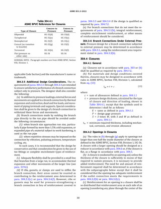
![ASME 831.3-2022
Figure 304.3.4
(22) Extruded Outlet Header Nomenclature
Limits of Centerline of
reinforcement
Header
Corrosion _]
Ly '=.$���������
allowance, c
T
MilI tolerance
(a)
Thickness, measured
or minimum per purchase
specification
c
Mill tolerance
[if required, see
illustration (d)J to
match branch pipe
1:3 maximum taper.
dx -1--Header
Extruded
outlet
-I
(c) [Note (2)1
28
Extrusion
taper
Extruded outlet
(b) [Note (1)]
Branch pipe
or nozzle
Limits of
reinforcement
zone
Extruded outlet
Header](https://image.slidesharecdn.com/26162943-231229160810-282cb07a/85/ASME-B31-3-2022-Procces-piping-code-for-b31-3-55-320.jpg)
![ASME 831.3-2022
Figure 304.3.4
Extruded Outlet Header Nomenclature (Cont'd)
Branch pipe
or nozzle
reinforcement
zone
rx
hx Ni'OI!---- dx --+--------IOHJ'
Required area
A1 = K (th) fdx)
Header
m�
Dh dh c ... 1�----- d2 -----1------ d2 -----1--�I
f j MUI '°''""�
{d} [Note (3)1
GENERAL NOTE: This Figure illustrates the nomenclature of para. 304.3.4. It does not indicate preferred design or fabrication details.
NOTES:
(1) Illustration to show method of establishing Tx when the taper encroaches on the crotch radius.
(2) Illustration is drawn for condition where K = 1.00.
(3) Illustration is drawn for condition where K = 1.00 and dx < db.
(d) Limitations on Radius rx, The external contour
radius, rx, is subject to the following limitations:
(1) minimum rx - the lesser of 0.05Db or 38 mm
(1.50 in.)
(2) maximum rx shall not exceed
(-a) for Db < ON 200 (NPS 8), 32 mm (1.25 in.)
(-b) for Db � ON 200, O.lDb + 13 mm (0.50 in.)
(3) for an external contour with multiple radii, the
requirements of (1) and (2) above apply, considering the
best-fit radius over a 45-deg arc as the maximum radius
(4J machining shall not be employed in order to meet
the above requirements
(e) Required Reinforcement Area. The required area of
reinforcement is defined by
A1 = Kthdx
(9)
where K is determined as follows:
(1) For Db/Dh > 0.60, K = 1.00.
(2) For 0.60 � Db/Dh > 0.15, K = 0.6 + %(Db/Dh).
(3) For Db/Dh :5 0.15, K = 0.70.
(fJ AvailableArea. The area available for reinforcement
is defined as
(9a)
29
These areas are all within the reinforcement zone and
are further defined below.
(1) Area A2 is the area resulting from excess thickness
in the header wall
(10)
(2) Area A3 is the area resulting from excess thickness
in the branch pipe wall
A3
= 2Ls
(Tb - tb - c) (11)
(3) Area A4 is the area resulting from excess thickness
in the extruded outlet lip
A4 = 2rx[Tx - (Tb - c)] (12)
(g) Reinforcement of Multiple Openings. The rules of
para. 304.3.3(e) shall befollowed, except that the required
area and reinforcement area shall be as given in this para
graph.
(h) Identification. The manufacturer shall establish the
design pressure and temperature for each extruded outlet
header and shall mark the header with this information,
together with the symbol "831.3" (indicating the](https://image.slidesharecdn.com/26162943-231229160810-282cb07a/85/ASME-B31-3-2022-Procces-piping-code-for-b31-3-56-320.jpg)
![ASME 831.3-2022
opening normal to the surface of the closure) will equal at
least one-half the required area in that plane.
(d) The total cross-sectional area required for rein
forcement in any given plane passing through the
center of the opening shall not be less than that
defined in ASME BPVC, Section VIII, Division 1, UG-37
(b), UG-38, and UG-39.
(e) The reinforcement area and reinforcement zone
shall be calculated in accordance with para. 304.3.3 or
para. 304.3.4, considering the subscript hand other refer
ences to the run or header pipe as applying to the closure.
Where the closure is curved, the boundaries of the rein
forcement zone shall follow thecontour of theclosure, and
dimensions of the reinforcement zone shall be measured
parallel to and perpendicular to the closure surface.
(j) If two or more openings are to be located in a
closure, the rules in paras. 304.3.3 and 304.3.4 for the re
inforcement of multiple openings apply.
(g) The additional design considerations for branch
connections discussed in para. 304.3.5 apply equally to
openings in closures.
304.5 Pressure Design of Flanges and Blanks
304.5.1 Flanges - General
(a) Flanges not in accordance with para. 303 or (b) or
(d) shall be qualified as required by para. 304.7.2.
(b) A flange may be designed in accordance with ASME
BPVC, Section VIII, Division 1, Mandatory Appendix 2
(Rules for Bolted Flange Connections with Ring Type
Gaskets) or ASME BPVC, Section VIII, Division 2, 4.16
(Design Rules for Flanged Joints), using the allowable
stresses and temperature limits of this Code. Nomencla
ture shall be as defined in Appendix 2, except as follows:
P = design gage pressure
S0 = bolt design stress at atmospheric temperature
Sb = bolt design stress at design temperature
s1 = product SEW [of the stress value, S; the appro
priate quality factor, E, from Table A-lA or
Table A-lB; and weld joint strength reduction
factor in accordance with para. 302.3.5(e)] for
flange or pipe material. See para. 302.3.2(e).
(c) The rules in (b)aboveare not applicabletoa flanged
joint having a gasket that extends outside the bolts
(usually to the outside diameter of the flange).
(d) For flanges that make solid contact outside the
bolts, ASME BPVC, Section VIII, Division 1, Appendix Y
should be used.
(e) See Section VIII, Division 1, Appendix S, for consid
erations applicable to bolted joint assembly.
304.5.2 Blind Flanges
(a) Blind flanges not in accordance with para. 303 or
(b) shall be qualified as required by para. 304.7.2.
31
(b) A blind flange may be designed in accordance with
eq. (14). The minimum thickness, considering the manu
facturer's minus tolerance, shall be not less than tm:
tm = t + c (14)
where c is the sum of allowances defined in para. 304.1.1.
To calculate t, the rules of ASME BPVC, Section VIII, Divi
sion 1, UG-34 may be used with the following changes to
the UG-34 nomenclature:
P = internal or external design gage pressure
SE = SEW [product of the basic allowable stress value,
S; the appropriate quality factor, E, from
Table A-lA or Table A-lB; and the weld joint
strength reduction factor, W, in accordance
with para. 302.3.5(e)] for flange material [see
para. 302.3.2(e)]
t = pressure design thickness, as calculated for the
given styles of blind flange, using the appropriate
equations for bolted flat cover plates in UG-34
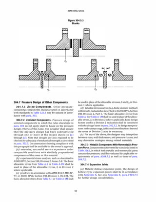
304.5.3 Blanks
(a) Blanks not inaccordance with para. 303 or (b) shall
be qualified as required by para. 304.7.2.
{b) The minimum required thickness of a permanent
blank (representative configurations shown in
Figure 304.5.3) shall be calculated in accordance with
eq. (15)
(15)
where
c = sum of allowances defined in para. 304.1.1
d9 = inside diameter of gasket for raised or flat face
flanges, or the gasket pitch diameter for ring
joint and fully retained gasketed flanges
E = same as defined in para. 304.1.1
P = design gage pressure
S = same as defined in para. 304.1.1
W = same as defined in para. 304.1.1
304.6 Reducers
304.6.1 Concentric Reducers
(a) Concentric reducers not in accordance with
para. 303 or (b) shall be qualified as required by para.
304.7.2.
(b) Concentric reducers made in a conical or reversed
curve section, or a combination of such sections, may be
designed in accordance with the rules for conical and tori
conical closures stated in para. 304.4.1.
304.6.2 Eccentric Reducers. Eccentric reducers not in
accordance withpara.303shallbequalifiedas required by
para. 304.7.2.](https://image.slidesharecdn.com/26162943-231229160810-282cb07a/85/ASME-B31-3-2022-Procces-piping-code-for-b31-3-58-320.jpg)
![ASME 831.3-2022
Table 314.2.1
Minimum Schedule of Components
With External Threads
Notch- Size Range
Sensitive [Note (2)] Minimum
Fluid Material Schedule
Service [Note (1)] DN NPS [Note (3)]
Normal Yes 540 511/z 80
50-150 2-6 40
>150 >6 None
No 5150 56 40
>150 >6 None
Category D Either All All None
NOTES:
(1) Carbon steel is generally considered to be notch sensitive,
whereas stainless steel is generally considered to be not
notch sensitive.
(2) For sizes over DN 50 (NPS 2), the joint shall be safeguarded (see
Appendix G) for a fluidservice that is flammable, toxic, ordama
ging to human tissue.
(3) Minimum schedules40 and BOarelisted inASME 836.lOM, which
areidenticaltoschedules405 andBOSlistedinASME B36.l9M for
DN 150 (NPS 6) and smaller.
315 TUBING JOINTS
315.1 General
Inselecting and applying flared, flareless, and compres
sion type tubing fittings, the designer shall consider the
possible adverse effects on the joints of such factors as
assembly and disassembly, cyclic loading, vibration,
shock, and thermal expansion and contraction.
315.2 Joints Conforming to Listed Standards
Jointsusing flared, flareless,orcompressiontype tubing
fittings covered by listed standards may beused in Normal
Fluid Service provided that
(a) the fittings and joints are compatible with the
tubing with which they are to be used (considering
maximum and minimum wall thickness) and are used
within the pressure-temperature limitations of the
fitting and the joint
{b) the joints are safeguarded when used under severe
cyclic conditions
315.3 Joints Not Conforming to Listed Standards
Jointsusing flared, flareless, or compression type tubing
fittings not listed inTable326.1may beused inaccordance
with para. 315.2 provided that the design is qualified in
accordance with para. 304.7.2.
38
316 CAULKED JOINTS
Caulked joints such as bell type joints shall be limited to
Category D Fluid Service and to a temperature not over
93°
C (200°
F). They shall be used within the pressure
temperature limitations of the joint and pipe. Provisions
shall be made to prevent disengagement of joints, to
prevent buckling of the piping, and to sustain lateral reac
tions produced by branch connections or other causes.
317 SOLDERED AND BRAZED JOINTS
317.1 Soldered Joints
Soldered joints shall be made in accordance with the
provisions of para. 333 and may be used only in Category
D fluid service. Fillet joints made with solder metal are not
permitted. The low melting point ofsolder shall beconsid
ered wherepossibleexposure to fireor elevated tempera
ture is involved.
317.2 Brazed and Braze Welded Joints
(a) Brazed and brazewelded joints madeinaccordance
with the provisions in para. 333 are suitable for Normal
Fluid Service. They shall be safeguarded in fluid services
that are flammable, toxic, or damaging to human tissue.
They shall not beused under severe cyclic conditions. The
melting point of brazing alloys shall be considered where
possible exposure to fire is involved.
(b) Fillet joints made with brazing filler metal are not
permitted.
318 SPECIAL JOINTS
Special joints are those not covered elsewhere in
Chapter II, Part 4, such as bell type and packed gland
type joints.
318.1 General
318.1.1 Listed Joints. Joints using listed components
are suitable for Normal Fluid Service.
318.1.2 Unlisted Joints. For joints that utilize unlisted
components, pressure design shall be qualified as
required by para. 304.7.2.
318.2 Specific Requirements
318.2.1 Joint Integrity. Separation of the joint shall be
prevented by ameans that has sufficient strength to with
stand anticipated conditions of service.
318.2.2 Joint Interlocks. Either mechanical or welded
interlocks shall be provided to prevent separation of any
joint used for a fluid service that is flammable, toxic, or
damaging to human tissues, of any joint to be used under
severe cyclic conditions, and of any joint exposed to
temperatures in the creep range.](https://image.slidesharecdn.com/26162943-231229160810-282cb07a/85/ASME-B31-3-2022-Procces-piping-code-for-b31-3-65-320.jpg)
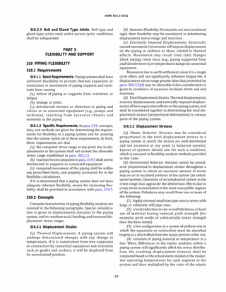
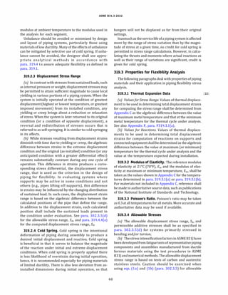
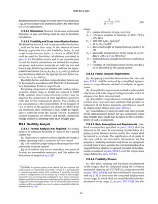
![ASME 831.3-2022
319.7 Means of Increasing Flexibility
The layout of piping often provides inherent flexibility
through changes in direction, so that displacements
produce chiefly bending and torsional strains within
prescribedlimits. Theamountofaxialtensionor compres
sion strain (which produces large reactions) usually is
small.
Where the piping lacks built-in changes of direction, or
where it is unbalanced [see para. 319.2.2(b)], large reac
tions or detrimental overstrain may be encountered. The
designer should consider adding flexibilitybyoneor more
of the following means: bends, loops, or offsets; swivel
joints; corrugated pipe; expansion joints of the bellows
or slip-joint type; or other devices permitting angular,
rotational, or axial movement. Suitable anchors, ties, or
other devices shall be provided as necessary to resist
end forces produced by fluid pressure, frictional resis
tance to movement, and other causes. When expansion
joints or other similar devices are provided, the stiffness
ofthejointor deviceshouldbeconsideredin anyflexibility
analysis of the piping.
320 ANALYSIS OF SUSTAINED LOADS
320.1 Basic Assumptions and Requirements
Sustained conditions may be evaluated by detailed
analysis, approximate methods, or simplified means
such as span tables. When detailed analysis is performed,
thestress duetosustainedloads, SL, shallbecomputedand
combined as described in this paragraph and shall not
exceed the allowable described in para. 302.3.S(c). See
Appendix S, Example 2 for guidance on loading conditions
andsupportscenarios thatresultinthegreatestSL foreach
operating condition being considered. The loads due to
weight should be based on the nominal thickness of all
system components unless otherwise justified in a
more rigorous analysis. Section moduli used to
compute the stresses in this paragraph shall be based
on nominal pipe dimensions less allowances, i.e., the
sum of mechanical (thread or groove depth), internal
and external corrosion, and erosion allowances. Areas
used to compute the stresses in this paragraph assume
nominal pipe dimensions less allowances affecting the
inside diameter of the pipe, i.e., the sum of mechanical
and internal corrosion and erosion allowances. It is the
responsibility of the designer to determine sustained
stress indices, Ia, I;, /0, and ft, when a piping component
is not explicitly addressed in ASME 831J, e.g., base-ells,
reducing elbows, crosses, close proximity fittings, etc.,
as well as elbows, pipe bends, or miters other than 90
deg or supported by a trunnion. Sustained stress
indices shall not be lower than 1.00.
44
320.2 Stress Due to Sustained Loads
The equation for the stress due to sustained loads, such
as pressure and weight, SL, is provided in eq. (23a). Equa
tions for the stress due to sustainedbending moments, Sb,
are presented in eq. (23b).
where
SL = �(ISal + Sb)
2
+ (2St)
2 (23a)
�(IiMi + (IaAfo)
2
Sb = --------
Z
(23b)
I; = sustained in-plane moment index. In the absence
ofmore-applicabledata,9
I; is taken as thegreater
of 0.7Si; or 1.00.
/0 sustained out-plane moment index. In the
absence of more-applicable data,9
/0 is taken
as the greater of 0.7Si0 or 1.00.
M; in-plane moment due to sustained loads, e.g.,
pressure and weight
M0 out-plane moment due to sustained loads, e.g.,
pressure and weight
Z = sustained section modulus.Zin eqs. (23b) and
(23c), is described in para. 319.4.4 but is
computed in this paragraph using nominal
pipe dimensions less allowances; seepara. 320.1.
The equation for the stress due to sustained torsional
moment, St, is
(23c)
where
ft = sustained torsionalmomentindex. In the absence
of more-applicable data,9
ft is taken as 1.00.
Mt = torsional moment due to sustained loads, e.g.,
pressure and weight
The equation for the stress due to sustained longitudinal
force, Sa, is
(23d)
where
AP = cross-sectional area of the pipe, considering
nominal pipe dimensions less allowances; see
para. 320.1
Fa longitudinal force due to sustained loads, e.g.,
pressure and weight
Ia sustainedlongitudinalforce index. In the absence
of more-applicable data,9
Ia is taken as 1.00.
9The sustained stress or moment factor determined from ASME 8311,
Table 1-1, General Note (d) may be considered as more applicable data.](https://image.slidesharecdn.com/26162943-231229160810-282cb07a/85/ASME-B31-3-2022-Procces-piping-code-for-b31-3-71-320.jpg)
![ASME 831.3-2022
(b) To protect terminal equipment or other (weaker)
portions of the system, restraints (such as anchors and
guides) shall be provided where necessary to control
movement or to direct expansion into those portions
of the system that are designed to absorb them. The
design, arrangement, and location of restraints shall
ensurethatexpansionjointmovementsoccurin the direc
tions for which the joint is designed. In addition to the
other thermal forces and moments, the effects of friction
in other supports of the system shall be considered in the
design of such anchors and guides.
(c) Piping layout, anchors, restraints, guides, and
supports foralltypes of expansion joints shallbedesigned
in accordance with Appendix X, para. X301.2.
321.2.2 Inextensible Supports Other ThanAnchors
and Guides10
(a) Supporting elements shall be designed to permit
the free movement of piping caused by thermal expansion
and contraction.
{b) Hangers include pipe and beam clamps, clips,
brackets, rods, straps, chains, and other devices. They
shall be proportioned for all required loads. Safe loads
for threaded parts shall be based on the root area of
the threads.
(c) Sliding Supports. Sliding supports (or shoes) and
brackets shall be designed to resist the forces due to fric
tion in addition to the loads imposed by bearing. The
dimensions of the support shall provide for the expected
movement of the supported piping.
321.2.3 Resilient Supports10
(a) Spring supports shall be designed to exert a
supporting force, at the point of attachment to the
pipe, equal to the load as determined by weight
balance calculations. They shall be provided with
means to prevent misalignment, buckling, or eccentric
loadingof the springs, and to prevent unintentional disen
gagement of the load.
(b) Constant-support spring hangers provide a
substantially uniform supporting force throughout the
range of travel. The use of this type of spring hanger is
advantageous at locations subject to appreciable move
ment with thermal changes. Hangers of this type
should be selected so that their travel range exceeds
expected movements.
(c) Means shall be provided to prevent overstressing
spring hangers due to excessive deflections. It is recom
mended that all spring hangers be provided with position
indicators.
321.2.4 Counterweight Supports. Counterweights
shall be provided with stops to limit travel. Weights
shall be positively secured. Chains, cables, hangers,
10 Various types of inextensible (solid) and resilient supports are il
lustrated in MSS SP-58.
46
rocker arms, or other devices used to attach the counter
weight load to the piping shall be subject to the require
ments of para. 321.2.2.
321.2.5 Hydraulic Supports. Anarrangement utilizing
a hydraulic cylinder may be used to give a constant
supporting force. Safety devices and stops shall be
provided to support the load in case of hydraulic failure.
321.3 Structural Attachments
External and internal attachments to piping shall be
designed so that they will not cause undue flattening
of the pipe, excessive localized bending stresses, or
harmfulthermal gradients in the pipewall. It is important
that attachments be designed to minimize stress concen
tration, particularly in cyclic services.
321.3.1 NonintegralAttachments. Nonintegralattach
ments, in which the reaction between the piping and the
attachmentisbycontact, includeclamps, slings, cradles, U
bolts, saddles, straps, and clevises. If the weight of a
vertical pipe is supported by a clamp, it is recommended
to prevent slippage that the clamp be located below a
flange, fitting, or support lugs welded to the pipe.
321.3.2 Integral Attachments. Integral attachments
include plugs, ears, shoes, plates, trunnions, stanchions,
structural shapes, and angle clips, cast on or welded to
the piping. Thematerialforintegralattachmentsattached
by welding shall be of good weldable quality. [See
para. 321.1.4(e) for material requirements.] Preheating,
welding, and heat treatment requirements shall be in
accordance with Chapter V. Consideration shall be
given to the localized stresses induced in the piping
component by welding the integral attachment, as well
as differential thermal displacement strains between
theattachment and the component towhichit is attached.
Welds shall be proportioned so that the shear stresses
meet the requirements of para. 302.3.l(b). If the
allowed stress values differ between the piping compo
nent and the attachment material, the lower of the two
values shall be used. Where postweld heat treatment
of the piping is required by para. 331, weldsfor structural
attachments made directly to pressure-containing mate
rials shall be postweld heat treated. Welds for structural
attachments not made directly to pressure-containing
materials do not require postweld heat treatment.
(a) Integral reinforcement, complete encirclement re
inforcement, or intermediate pads of suitable alloy and
design may be used to reduce contamination or undesir
able heat effects in alloy piping.
(b) Intermediate pads, integral reinforcement,
complete encirclement reinforcement, or other means
of reinforcement may be used to distribute stresses.
The design of pipe-supporting elements and the local
effects on the piping component are the responsibility of
the designer. Nonmandatory guidance on the design of](https://image.slidesharecdn.com/26162943-231229160810-282cb07a/85/ASME-B31-3-2022-Procces-piping-code-for-b31-3-73-320.jpg)
![ASME 831.3-2022
Chapter Ill
Materials
323 GENERAL REQUIREMENTS
Chapter III states limitations and required qualifica
tions for materials based on their inherent properties.
Their use in piping is also subject to requirements and
limitations in other parts of this Code [see para.
300(d)]. See also para. 321.1.4 for support materials,
and Appendix F, para. F323, for precautionary considera
tions.
323.1 Materials and Specifications
323.1.1 Listed Materials. Any material used in pres
sure-containing piping components shall conform to a
listed specification except as provided in para. 323.1.2.
323.1.2 Unlisted Materials. Unlisted materials may be
used provided they conform to a published specification
covering chemistry, physical and mechanical properties,
method and process of manufacture, heat treatment, and
quality control, and otherwise meet the requirements of
thisCode.SeealsoASME BPVC, Section II, Part D, Appendix
S. Allowable stresses shall be determined in accordance
with the applicable allowable stress basis of this Code or a
more conservative basis.
323.1.3 Unknown Materials. Materials of unknown
specification shall not be used for pressure-containing
piping components.
323.1.4 Reclaimed Materials. Reclaimed pipe and
other piping components may be used, provided they
are properly identified as conforming to a listed or
published specification (para. 323.1.1 or para. 323.1.2)
and otherwise meet the requirements of this Code. Suffi
cient cleaning and inspection shall be made to determine
minimum wall thickness and freedom from imperfections
that would be unacceptable in the intended service.
323.2 Temperature Limitations
The designer shall verify that materials that meet other
requirements of the Code are suitable for service
throughout the operating temperature range.
323.2.1 Upper Temperature Limits, Listed Materials.
A listed material may be used at a temperature above the
maximum for which a stress value or rating is shown, only
if
(a) there is no prohibition in Appendix A or elsewhere
in the Code
(b) the designer verifies the serviceability of the mate
rial in accordance with para. 323.2.4
49
323.2.2 Lower Temperature Limits, Listed Materials. (22)
Listed materials shall be tested as described in
Table 323.2.2 except as exempted by (d) through Ci).
See Appendix F, para. F323.2.2.
(a) The allowable stress or component rating at any
temperature colder than the minimum shown in Table
A-1, Table A-lM, or Figure 323.2.2A shall not exceed
the stress value or rating at the minimum temperature
in Table A-1, Table A-lM, or the component standard.
(b) The stress ratio is used in Figure 323.2.28 to deter
mine theallowable reduction in the impact test exemption
temperature. Thestressratio isdefinedasthemaximumof
the following:
(1) circumferential pressure stress for the condition
under consideration (based on minimum pipe wall thick
ness lessallowances)divided by the basicallowable stress
at the condition under consideration.
(2) for piping components with pressure ratings, the
pressure for theconditionunderconsiderationdivided by
the pressure rating at the condition under consideration.
(3) combined stress due to pressure, dead loads, live
loads, and displacement strain for the condition under
consideration divided by the basic allowable stress at
the condition under consideration. In calculating this
combined stress, the forces and moments in the piping
system for these combined sustained loads and displace
ment strains shall be calculated using nominal dimen
sions, and the stresses shall be calculated using
eqs. (23a) through (23d) with all of the stress indices
takenas1.0 Ua = I; /0 = ft
= 1.0)andusingsectionproperties
based on the nominal dimensions less corrosion, erosion,
and mechanical allowances. Also see Appendix F, para.
F323.2.2.
(c) Minimum impact test exemption temperature
reduction may be used only when all of the following
apply:
(1) The piping is not in Elevated Temperature Fluid
Service.
(2) Local stresses caused by shock loading, thermal
bowing, and differential expansion between dissimilar
metals (e.g., austenitic welded to ferritic) are less than
10% of the basic allowable stresses at the condition
under consideration.
(3) The piping is safeguarded from maintenance
loads, e.g., using a valve wheel wrench on a small bore
valve.
(d) Impact testing of the base metal is not required if
the design minimum temperature iswarmer than or equal
to the temperature listed in the Min. Temp. column of](https://image.slidesharecdn.com/26162943-231229160810-282cb07a/85/ASME-B31-3-2022-Procces-piping-code-for-b31-3-76-320.jpg)
![(22)
ASME 831.3-2022
Table 323.2.2
Requirements for Low Temperature Toughness Tests for Metals
Column B
Design Minimum
Temperature Colder Than
Column A Minimum Temperature in
Design Minimum Temperature atorWarmer Than Minimum Table A-1, Table A-lM,
Temperature in Table A-1, Table A-lM, or Figure 323.2.2A or Figure 323.2.2A or as
Type of Material or as Described in Para. 323.2.2(h) Described in Para. 323.2.2(h)
Listed 1 Gray iron A-1 No additional requirements B-1 No additional requirements
Materials 2 Malleable and ductile A-2 No additional requirements B-2 Materials designated in
iron; carbon steel in Box 2 shall not be used.
accordance with
Note (1)
(a) Base Metal (b) Weld Metal [Note (2)]
3 Other carbon steels; low A-3 (a) No additional A-3 (b) The weld metal of the B-3 Each heat,test unit,or lot of
and intermediate alloy requirements welding procedure qualification base material as identified in
steels; and ferritic, test coupon shall be impact the applicable base metal
martensitic, and duplex tested at or below the design specification shall be impact
stainless steels minimum temperature when tested except when Note (3)
that temperature is less than or Note (4) is satisfied. When
-18°
C (0°
F), except when materials are subjected to
Note (3) or Note (4) is satisfied; heat treatment during fabri-
impact testing of the weld metal cation,including hot bending
is not required when the clas- or forming and postweld heat
sification of the welding treatment such as that
consumables according to the required by Table 331.1.1,
filler metal specification impact testing shall be
requires impact testing at or performed on material that
below the design minimum has been subjected to heat
temperature. treatment simulating the
anticipated heat treatment,
including, for postweld heat
treatment,at least 80% of the
time at temperature. Each
welding procedure specifica-
tion shall be qualified in
accordance with Table
323.3.1.
4 Austenitic stainless steels A-4 (a) If A-4 (b) Weld metal deposits shall B-4 Base metal and weld metal
(1) carbon content by be impact tested in accordance deposits shall be impact
analysis >0.1% or with para. 323.3 if design tested in accordance with
(2) material is not in minimum temperature para. 323.3.See Notes (2),(5),
solution heat treated <-29°
C (<-20°
F) except as and (6).
condition, then impact provided in para. 323.2.2 and in
test in accordance with Notes (5) and (6)
para. 323.3 for design
minimum temperature
<-29°
C (<-20°
F) except
as provided in
Notes (5) and (6)
5 Austenitic ductile iron, A-5 (a) No additional A-5 (b) Welding is not permitted. B-5 Base metal shall be impact
ASTM A571 requirements tested in accordance with
para 323.3. Do not use
<-l96°
C (<-320°
F). Welding
is not permitted.
6 Aluminum, copper, A-6 (a) No additional A-6 (b) No additional B-6 Designer shall be assured
nickel, and their alloys; requirements requirements unless filler by suitable tests [see
unalloyed titanium metal composition is outside Note (7)] that base metal,
the range for base metal weld deposits, and HAZ are
composition; then test in suitable at the design
accordance with item 8-6 minimum temperature
Unlisted 7 An unlisted material shall conform to a published specification. Where composition, heat treatment, and product form are
Materials comparable to those of a listed material, requirements for the corresponding listed material shall be met. Other unlisted
materials shall be qualified as required in the applicable section of column B.
GENERAL NOTE: These toughness test requirements are in addition to tests required by the material specification.
NOTES:
(1) Carbonsteelsconformingto the following aresubjectto the limitations in Box 8-2: plates in accordance withASTMA36,A283,andA570; pipe
in accordance withASTMAl34 when made from these plates; structural shapes in accordance withASTMA992; and pipe in accordance with
ASTM A53 Type F and AP! SL Gr. A25 CW.
(2) Impact tests that meet the requirements of Table 323.3.1,which are performed as part of the weld procedure qualification,will satisfy all
requirements of para. 323.2.2, and need not be repeated for production welds.
so](https://image.slidesharecdn.com/26162943-231229160810-282cb07a/85/ASME-B31-3-2022-Procces-piping-code-for-b31-3-77-320.jpg)
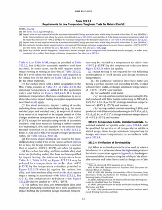
![(22)
ASME 831.3-2022
Figure 323.2.2A
Minimum Temperatures Without Impact Testing for Carbon Steel Materials
Nominal Thickness, 'f, in. [Note (1)]
0 0.394 0.5 1.0 1.5 2.0 2.5 3.0
130
50 120
110
40
100
90
30
80
�- 20
70
0. 10
E
60
50
Q)
0.
E
� 40 �
E E
:::,
0
-�
30 :::,
c
� -8
20 �
18
§, -10
"iii
Q)
Cl
10
"iii
Q)
0 Cl
-20
-10
-29 -20
-30
-30
-40 -40
-48 -55
-50 -60
0 10 20 30 40 50 60 70
Nominal Thickness, 'f, mm [Note (1)]
GENERAL NOTE: See Table A-1 or Table A-lM for the designated curve for a listed material; see Table 323.2.2A for tabular values.
NOTES:
(1) For blind flanges and blanks made from materials with a letter designation in the Min. Temp. column of TableA-1 or TableA-lM, Tshall be%
of the total thickness, where the total thickness is the thickness of the blind flange or blank including the thickness of the facing(s), if
applicable.
(2) Any carbon steel material may be used to a minimum temperature of -29°
C (-20°
F) for Category D Fluid Service.
(3) X and L grades of API SL PSLl, 290 and stronger grades of CSA Z245.l, and ASTM A381 materials may be used in accordance with Curve B if
normalized or quenched and tempered.
(4) The following materials may be used in accordance with Curve D if normalized:
(a) ASTM A516 plate, all grades
(b) ASTM A671 pipe made from A516 plate, all grades
(c) ASTM A672 pipe made from A516 plate, all grades
(5) A welding procedure for the manufacture of pipe or components shall include impact testing of welds and HAZ for any design minimum
temperature below -29°
C (-20°
F), except as provided in Table 323.2.2, A-3(b).
(6) Impact testing in accordancewith para. 323.3 is required for any design minimum temperaturebelow -48°
C (-55°
F), except as permitted by
Note (3) in Table 323.2.2.
52](https://image.slidesharecdn.com/26162943-231229160810-282cb07a/85/ASME-B31-3-2022-Procces-piping-code-for-b31-3-79-320.jpg)
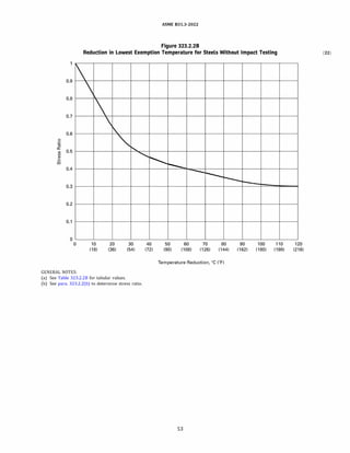
![ASME 831.3-2022
Table 323.2.2A
(22) Tabular Values for Minimum Temperatures Without Impact Testing for Carbon Steel Materials
Lowest Exemption Temperature
Nominal Thickness, Curve A Curve B Curve C
'f [Note (1}] [Note (2}] [Note (3}] [Note (3}] Curve D
mm in. oc Of oc Of oc Of oc Of
6.4 0.25 -8 18 -29 -20 -48 -55 -48 -55
7.9 0.3125 -8 18 -29 -20 -48 -55 -48 -55
9.5 0.375 -8 18 -29 -20 -48 -55 -48 -55
10.0 0.394 -8 18 -29 -20 -48 -55 -48 -55
11.1 0.4375 -4 25 -29 -20 -40 -40 -48 -55
12.7 0.5 0 32 -29 -20 -37 -34 -48 -55
14.3 0.5625 3 37 -22 -7 -32 -26 -46 -51
15.9 0.625 6 43 -17 2 -30 -22 -44 -48
17.5 0.6875 9 48 -13 9 -28 -18 -43 -45
19.1 0.75 12 53 -9 15 -26 -15 -41 -42
20.6 0.8125 14 57 -7 20 -24 -12 -39 -38
22.2 0.875 16 61 -4 25 -23 -9 -38 -36
23.8 0.9375 18 65 -2 29 -21 -6 -36 -33
25.4 1.0 20 68 1 33 -19 -3 -34 -30
27.0 1.0625 22 72 2 36 -18 -1 -33 -28
28.6 1.125 24 75 4 39 -17 2 -32 -26
30.2 1.1875 25 77 6 42 -16 4 -31 -23
31.8 1.25 27 80 7 44 -14 6 -29 -21
33.3 1.3125 28 82 8 46 -13 8 -28 -19
34.9 1.375 29 84 9 48 -12 10 -28 -18
36.5 1.4375 30 86 9 49 -11 12 -27 -16
38.1 1.5 31 88 11 51 -10 14 -26 -14
39.7 1.5625 32 90 12 53 -9 16 -25 -13
41.3 1.625 33 92 13 55 -8 17 -24 -11
42.9 1.6875 34 93 14 57 -7 19 -23 -10
44.5 1.75 34 94 14 58 -7 20 -22 -8
46.0 1.8125 36 96 15 59 -6 22 -22 -7
47.6 1.875 36 97 16 61 -5 23 -21 -6
49.2 1.9375 37 98 17 62 -4 24 -21 -5
50.8 2.0 37 99 17 63 -3 26 -20 -4
52.4 2.0625 38 100 18 64 -3 27 -19 -3
54.0 2.125 38 101 18 65 -2 28 -19 -2
55.6 2.1875 39 102 19 66 -2 29 -18 -1
57.2 2.25 39 102 19 67 -1 30 -18 0
58.7 2.3125 39 103 20 68 -1 31 -17 1
60.3 2.375 40 104 21 69 0 32 -17 2
61.9 2.4375 41 105 21 70 1 33 -16 3
63.5 2.5 41 105 22 71 1 34 -16 4
65.1 2.5625 41 106 22 71 2 35 -15 5
66.7 2.625 42 107 23 73 2 36 -14 6
68.3 2.6875 42 107 23 73 3 37 -14 7
69.9 2.75 42 108 23 74 3 38 -13 8
71.4 2.8125 42 108 24 75 4 39 -13 8
73.0 2.875 43 109 24 76 4 40 -13 9
74.6 2.9375 43 109 25 77 4 40 -12 10
76.2 3.0 43 110 25 77 5 41 -12 11
GENERAL NOTE: See Figure 323.2.2A for curves.
54](https://image.slidesharecdn.com/26162943-231229160810-282cb07a/85/ASME-B31-3-2022-Procces-piping-code-for-b31-3-81-320.jpg)
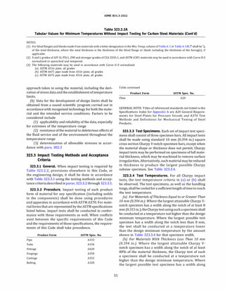
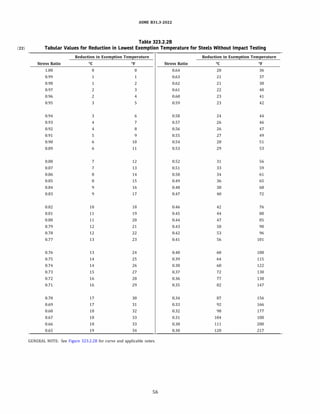
![Test Characteristics
Tests Number of
on tests
Materials
Location and
orientation
of specimens
Tests by
Tests Qualification
on Welds requirements
in Extent of testing
Fabrication [Note (3)]
or Assembly
Location and
orientation
of specimens
Tests by
NOTES:
ASME 831.3-2022
Table 323.3.1
Impact Testing Requirements for Metals
Column A Column B
Materials Tested by the Manufacturer [Note (1)] Materials Not Tested by the Manufacturer
or Those in Table 323.2.2 Requiring Impact Tests or Those Tested But Heat Treated During
Only on Welds or After Fabrication
A-1 The greater of the number required by B-1 The number required by the applicable
(a) the material specification or specification listed in para. 323.3.2
(b) the applicable specification listed in [Note (2)]
para. 323.3.2 (Note (2)]
2 As required by the applicable specification listed in para. 323.3.2.
A-3 The manufacturer B-3 The fabricator or erector
4 The supplementary essential variables of ASME BPVC, Section IX, shall apply to the welding
procedure qualification.
A-5 Impacttests shallbe performedontheweldmetal B-5 If simulated heat treatment is required by
and the heat-affected zone (HAZ) of the procedure Table 323.2.2, item B-3, and materials were
qualification test coupon at or below the design supplied without impact test data based on
minimum temperature and shall meet the test pieces that were subjected to such heat
acceptance criteria applicable to the base metal in treatment, the fabricator or erector shall
accordance with para. 323.3. conduct impact tests on material that has
been given such heat treatment.
6
(a) Weld metal: across the weld, with notch in the weld metal; notch axis shall be normal to material
(b)
surface, with one face of specimen 51.5 mm (51
/16 in.) from the material surface.
HAZ: across the weld and long enough to locate notch in the HAZ after
etching; notch axis shall be approximately normal to material surface and shall include as
much as possible of the HAZ in the fracture.
7 The fabricator or erector
(1) A certified report of impact tests performed (after being appropriately heat treated as required by Table 323.2.2, item B-3) by the manu
facturershall be obtainedasevidencethatthematerial (including anyweldsused initsmanufacture) meetstherequirements ofthis Code and
that
(a) the tests were conducted on specimens representative of the material delivered to and used by the fabricator or erector, or
(b) the tests were conducted on specimens removed from test pieces of the material which received heat treatment separately in the same
manner as the material (including heat treatment by the manufacturer) so as to be representative of the finished piping
(2) If welding is used in manufacture, fabrication, or erection, tests of the HAZ will suffice for the tests of the base material.
(3) The test piece shall be large enough to permit preparing three specimens from the weld metal and three from the HAZ (if required) in
accordance with para. 323.3. If this is not possible, preparation of additional test pieces is required.
the notch of less than 80% of the material thickness, the
test shall be conducted at a temperature lower than the
design minimum temperature by an amount equal to the
difference (referring to Table 323.3.4) between the
temperature reduction corresponding to the actual mate
rial thickness and the temperature reduction corre
sponding to the Charpy specimen width actually tested.
323.3.5 Acceptance Criteria
(a) Minimum Energy Requirements. Except for bolting
materials, the applicable minimum energy requirement
for carbon and low alloy steels with specified
minimum tensile strengths less than 656 MPa (95 ksi)
shall be those shown in Table 323.3.5.
57
(b) Lateral Expansion Requirements. Other carbon and
low alloy steels having specified minimum tensile
strengths equal to or greater than 656 MPa (95 ksi),
all bolting materials, and all high alloy steels (P-Nos. 6,
7, 8, lOH, and 101) shall have a lateral expansion opposite
the notch of not less than 0.38 mm (0.015 in.) for all
specimen sizes. The lateral expansion is the increase in
width of the broken impact specimen over that of the
unbroken specimen measured on the compression
side, parallel to the line constituting the bottom of the
V-notch (see ASTM A370).
(c) Weld Impact Test Requirements. Where two base
metals having different required impact test acceptance
criteria are joined by welding, the impact test acceptance
criteria shall conform to the requirements of the base](https://image.slidesharecdn.com/26162943-231229160810-282cb07a/85/ASME-B31-3-2022-Procces-piping-code-for-b31-3-84-320.jpg)
![(22)
ASME 831.3-2022
Table 323.3.4
Charpy Impact Test Temperature Reduction
Temperature
Reduction
Actual Material Thickness Below Design
[See Para. 323.3.4(b)] or Charpy Impact Minimum
Specimen Width Along the Notch [Note (1)] Temperature
mm in. oc Of
10 (full size standard bar) 0.394 0 0
9 0.354 0 0
8 0.315 0 0
7.5 (% size bar) 0.295 3 5
7 0.276 4 8
6.67 (% size bar) 0.262 6 10
6 0.236 8 15
5 (112 size bar) 0.197 11 20
4 0.157 17 30
3.33 (% size bar) 0.131 19 35
3 0.118 22 40
2.5 (% size bar) 0.098 28 50
GENERAL NOTE: These temperature reduction criteria do not apply
when Table 323.3.5specifieslateral expansion for minimum required
values.
NOTE: (1) Straight-line interpolation for intermediate values is
permitted.
material having a specified minimum tensile strength
most closely matching the specified minimum tensile
strength of the weld metal.
{d) Retests
(1) For Absorbed Energy Criteria. When the average
value of the three specimens equals or exceeds the
minimum value permitted for a single specimen and
the value for more than one specimen is below the
required average value, or when the value for one
specimen is below the minimum value permitted for a
single specimen, a retest of three additional specimens
shallbe made.Thevaluefor each oftheseretestspecimens
shall equal or exceed the required average value.
(2) For Lateral Expansion Criterion. If the value of
lateral expansion for one specimen in a group of three
is below 0.38 mm (0.015 in.) but not below 0.25 mm
(0.01 in.), and if the average value for three specimens
equals or exceeds 0.38 mm (0.015 in.), a retest of
three additional specimens may be made, each of
which must equal or exceed the specified minimum
value of 0.38 mm (0.015 in.). In the case of heat
58
treated materials, if the required values are not obtained
in the retest or if the values in the initial test are below the
minimum allowed for retest, the material may be reheat
treated and retested.After reheat treatment, a set of three
specimens shall be made. For acceptance, the lateral
expansion of each of the specimens must equal or
exceed the specified minimum value of 0.38 mm
(0.015 in.).
(3) For Erratic Test Results. When an erratic result is
caused by a defective specimen or there is uncertainty in
the test procedure, a retest will be allowed.
323.4 Fluid Service Requirements for Materials
323.4.1 General. Requirements in para. 323.4 apply to
pressure-containingparts.They do not apply to materials
used for supports, gaskets, packing, or bolting. See also
Appendix F, para. F323.4.
323.4.2 Specific Requirements
(a) Ductile Iron. Ductile iron shall not be used for pres
sure containing parts at temperatures below -29°
C
(-20°
F) (except austenitic ductile iron) or above 343°
C
(650°
F). Austenitic ductile iron conforming to ASTM
A571 may be used at temperatures below -29°
C
(-20°
F) down to the temperature of the impact test
conducted in accordance with that specification but
not below -196°
C (-320°
F).
Valves having bodies and bonnets or covers made of
materials conforming to ASTM A395 and meeting the re
quirements of ASME 816.42 and additional requirements
of ASME 816.34 Standard Class, AP! 594, AP! 599, or AP!
609maybeused withinthepressure-temperatureratings
given in ASME 816.42.
Welding shall not be performed in the fabrication or
repair of ductile iron components nor in assembly of
such components in a piping system.
(bJ Other Cast Irons. The following shall not be used
under severe cyclicconditions. If safeguarding isprovided
against excessiveheat and thermal shock and mechanical
shock and abuse, they may be used in other services
subject to the following requirements:
(1) Gray iron shall not be used above ground within
process unit limits in hydrocarbon or other flammable
fluid service at temperatures above 149°
C (300°
F) nor
at gagepressuresabove 1035kPa (150psi). In other loca
tions the pressure limit shall be 2760 kPa (400 psi).
(2) Malleable iron shall not be used in any fluid
service at temperatures below -29°
C (-20°
F) or above
343°
C (650°
F) and shall not be used in flammable fluid
service at temperatures above 149°
C (300°
F) nor at
gage pressures above 2760 kPa (400 psi).
(3) High silicon iron (14.5% Si) shall not be used in
flammable fluid service. The manufacturer should be
consulted for pressure-temperature ratings and for
precautionary measures when using this material.](https://image.slidesharecdn.com/26162943-231229160810-282cb07a/85/ASME-B31-3-2022-Procces-piping-code-for-b31-3-85-320.jpg)
![ASME 831.3-2022
Table 323.3.5
Minimum Required Charpy V-Notch Impact Values
Energy [Note (2)]
Fully Deoxidized Other Than Fully
Specified Minimum Number of Specimens Steels Deoxidized Steels
Tensile Strength [Note (1)] Joules ft-lbf Joules ft-lbf
(a) Carbon and Low Alloy Steels
448 MPa (65 ksi) and less Average for 3 specimens 18 13 14 10
Minimum for 1 specimen 14 10 10 7
Over 448 to 517 MPa (75 ksi) Average for 3 specimens 20 15 18 13
Minimum for 1 specimen 16 12 14 10
Over 517 but not incl. 656 MPa (95 ksi) Average for 3 specimens 27 20
Minimum for 1 specimen 20 15
Lateral Expansion
656 MPa and over (Note (3)] Minimum for 3 specimens 0.38 mm (0.015 in.)
(b) Steels in P-Nos. 6, 7, 8, lOH, and 101 Minimum for 3 specimens 0.38 mm (0.015 in.)
NOTES:
(1) See para. 323.3.S(d) for permissible retests.
(2) Energy values in this Table are for standard size specimens. For subsize specimens, these values shall be multiplied by the ratio of the actual
specimen width to that of a full-size specimen, 10 mm (0.394 in.).
(3) For bolting of this strength level in nominal sizes M 52 (2 in.) and under, the impact requirements ofASTM A320 may be applied. For bolting
over M 52, requirements of this Table shall apply.
(c) Other Materials
(1) If welding or thermal cutting is performed on
aluminum castings, the stress values in Appendix A
and component ratings listed in Table 326.1 are not ap
plicable.Itis the designer'sresponsibilitytoestablishsuch
stresses and ratings consistent with the requirements of
this Code.
(2) Lead and tin and their alloys shall not be used in
flammable fluid services.
323.4.3 Cladding and Lining Materials. Materials with
metallic cladding or metallic lining may be used in accor
dance with the following provisions:
(a) If piping components are made from integrally clad
plate conforming to
(1) ASTM A263, Corrosion-Resisting Chromium
Steel Clad Plate, Sheet, and Strip
(2) ASTM A264, Stainless Chromium-Nickel Steel
Clad Plate, Sheet, and Strip
(3) ASTM A265, Nickel and Nickel-Base Alloy Clad
Plate, Sheet, and Strip
Then pressure design in accordance with rules in
para. 304 may be based upon the total thickness of
basemetal and cladding after any allowance for corrosion
has been deducted, provided that both the base metal and
the cladding metal are acceptable for Code use under para.
323.1, and provided that the clad plate has been shear
tested and meets all shear test requirements of the appli
cable ASTM specification. The allowable stress for each
59
material (base and cladding) shall be taken from
Appendix A, or determined in accordance with the
rulesinpara. 302.3, provided, however, that the allowable
stress used for thecladdingportionofthe designthickness
shall never be greater than the allowable stress used for
the base portion.
(b) For all other metallic clad or lined piping compo
nents, the base metal shall be an acceptable Code material
as defined in para. 323.1 and the thickness used in pres
sure design in accordance with para. 304 shall not include
thethicknessofthecladdingorlining.Theallowablestress
used shallbe that for the base metalatthe design tempera
ture. For such components, the cladding or lining may be
any material that, in the judgment of the user, is suitable
for the intended service and for the method of manufac
ture and assembly of the piping component.
(c) Except for componentsdesigned inaccordance with
provisions of (a), fluid service requirements for materials
stated inthisCode shallnotrestrict theiruseas claddingor
lining in pipe or other components. Fluid service require
ments for the outer material (including those for compo
nents and joints) shall govern, except that temperature
limitations of both inner and outer materials, and of
any bond between them, shall be considered.
{d) Fabrication by welding of clad or lined piping
componentsandtheinspectionandtestingofsuchcompo
nents shall be done in accordance with applicable provi
sions of ASME BPVC, Section VIII, Division 1, UCL-30](https://image.slidesharecdn.com/26162943-231229160810-282cb07a/85/ASME-B31-3-2022-Procces-piping-code-for-b31-3-86-320.jpg)
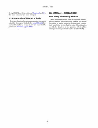
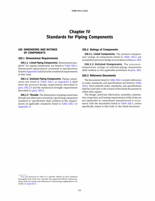
![(22)
ASME 831.3-2022
Table 326.1
Component Standards
Standard or Specification
Bolting
Square, Hex, Heavy Hex, and Askew Head Bolts and Hex, Heavy Hex, Hex Flange, Lobed Head, and Lag Screws
(Inch Series) .................................................................................
Nuts for General Applications: Machine Screw Nuts, Hex, Square, Hex Flange, and Coupling Nuts (Inch Series) . . . .
Continuous Thread Stud, Double-End Stud, and Flange Bolting Stud (Stud Bolt) (Inch Series) ..................
Metallic Fittings, Valves, and Flanges
Gray Iron Pipe Flanges and Flanged Fittings: Classes 25, 1 25, and 250 .....................................
Malleable Iron Threaded Fittings: Classes 150 and 300 .................................................
Gray Iron Threaded Fittings: Classes 1 25 and 250 .....................................................
Pipe Flanges and Flanged Fittings: NPS 1/z Through NPS 24 Metric/Inch Standard ...........................
Factory-Made Wrought Buttwelding Fittings ..........................................................
Face-to-Face and End-To-End Dimensions of Valves ....................................................
Forged Fittings, Socket-Welding and Threaded ........................................................
Ferrous Pipe Plugs, Bushings, and Locknuts With Pipe Threads ..........................................
Cast Copper Alloy Threaded Fittings: Classes 1 25 and 250 (Note ( 1)] ......................................
Cast Copper Alloy Solder Joint Pressure Fittings .......................................................
Wrought Copper and Copper Alloy Solder-Joint Pressure Fittings .........................................
Cast Copper Alloy Pipe Flanges, Flanged Fittings, and Valves: Classes 150, 300, 600, 900, 1500, and 2500 ........
Cast Copper Alloy Fittings for Flared Copper Tubes ....................................................
Valves - Flanged, Threaded, and Welding End .......................................................
Orifice Flanges ..................................................................................
Malleable Iron Threaded Pipe Unions: Classes 150, 250, and 300 .........................................
Ductile Iron Pipe Flanges and Flanged Fittings: Classes 150 and 300 ......................................
Large Diameter Steel Flanges: NPS 26 Through NPS 60 Metric/Inch Standard ...............................
Line Blanks ....................................................................................
Wrought Copper and Copper Alloy Braze-Joint Pressure Fittings ..........................................
Bioprocessing Equipment [Note ( 2)] ................................................................
Specification for Pipeline and Piping Valves [Note ( 3)] ..................................................
Flanged Steel Pressure-relief Valves .................................................................
Check Valves: Flanged, Lug, Wafer, and Butt-welding ...................................................
Metal Plug Valves - Flanged, Threaded, and Welding Ends .............................................
Steel Gate Valves - Flanged and Butt-welding Ends, Bolted Bonnets ......................................
Gate, Globe, and Check Valves for Sizes DN 100 (NPS 4) and Smaller for the Petroleum and Natural Gas Industries
Corrosion-resistant, Bolted Bonnet Gate Valves - Flanged and Butt-welding Ends ...........................
Metal Ball Valves - Flanged, Threaded, and Welding Ends ..............................................
Butterfly Valves: Double-flanged, Lug- and Wafer-type, and Butt-welding Ends
Performance of Gasketed Mechanical Couplings for Use in Piping Applications ..............................
Performance of Fittings for Use with Gasketed Mechanical Couplings Used in Piping Applications
Ductile-Iron and Gray-Iron Fittings .................................................................
Flanged Ductile-Iron Pipe With Ductile-Iron or Gray-Iron Threaded Flanges ................................
Steel Pipe Flanges for Waterworks Service, Sizes 4 in.Through 144 in.( 100 mm Through 3,600 mm) ...........
Dimensions for Fabricated Steel Water Pipe Fittings ...................................................
Stainless-Steel Pipe Flange Joints for Water Service - Sizes 2 in.Through 7 2 in.(SO mm Through 1,800 mm) ....
Metal-Seated Gate Valves for Water Supply Service ....................................................
Standard Finishes for Contact Faces of Pipe Flanges and Connecting-End Flanges of Valves and Fittings ..........
62
Designation
ASME 818.2.1
ASME 818.2.2
ASME 818.3 1.2
ASME 816.1
ASME 816.3
ASME 816.
4
ASME 816.
5
ASME 816.
9
ASME 816.10
ASME 816.1 1
ASME 816.14
ASME 816.15
ASME 816.18
ASME 816.2 2
ASME 816.24
ASME 816.26
ASME 816.34
ASME 816.36
ASME 816.39
ASME 816.
4 2
ASME 816.
47
ASME 816.
48
ASME 816.
50
ASME BPE
API 60
API 5 26
API 594
API 599
API 600
API 60 2
API 60 3
API 608
API 609
ASTM F 1476
ASTM F 1548
AWWA C 1 10
AWWA C 1 15
AWWA C 207
AWWA C 208
AWWA C 2 28
AWWA CSOO
MSS SP-6](https://image.slidesharecdn.com/26162943-231229160810-282cb07a/85/ASME-B31-3-2022-Procces-piping-code-for-b31-3-89-320.jpg)
![ASME 831.3-2022
Table 326.1
Component Standards (Cont'd)
Standard or Specification
Metallic Fittings, Valves, and Flanges (Cont'd)
Spot Facing for Bronze, Iron, and Steel Flanges .......................................................
Standard Marking System for Valves, Fittings, Flanges, and Unions ........................................
Corrosion-Resistant Gate, Globe, Angle, and CheckValves with Flanged and Butt Weld Ends (Classes 150, 300, and 6 00)
Wrought and Fabricated Butt-Welding Fittings for Low Pressure, Corrosion Resistant Applications [Note (4)] .....
Steel Pipeline Flanges ............................................................................
Drain and Bypass Connections .....................................................................
Class 150LW Corrosion Resistant Flanges and Cast Flanged Fittings.......................................
High-Pressure Chemical Industry Flanges and Threaded Stubs for Use with Lens Gaskets ......................
Gray Iron Gate Valves, Flanged and Threaded Ends ....................................................
Gray Iron Swing Check Valves, Flanged and Threaded Ends..............................................
Ball Valves with Flanged or Butt-Welding Ends for General Service .......................................
High-Strength, Wrought, Butt-Welding Fittings ........................................................
Gray Iron Plug Valves, Flanged and Threaded Ends....................................................
Socket Welding Reducer Inserts ....................................................................
Bronze Gate, Globe, Angle, and Check Valves ..........................................................
Stainless-Steel or Stainless-Steel-Lined, Bonnetless, Knife Gate Valves with Flanged Ends ......................
Class 3000 and 6 000 Pipe Unions, Socket Welding and Threaded (Carbon Steel, Alloy Steel, Stainless Steels, and Nickel
Alloys) ......................................................................................
Gray Iron Globe and Angle Valves, Flanged and Threaded Ends ..........................................
Diaphragm Valves ...............................................................................
Swage(d) Nipples and Bull Plugs...................................................................
Integrally Reinforced Forged Branch Outlet Fittings - Socket Welding, Threaded, and Buttwelding Ends .........
Instrument Valves for Code Applications .............................................................
Cast Copper Alloy Flanges and Flanged Fittings: Class 1 2
5, 150, and 300 ...................................
Factory-Made Wrought Belled End Pipe Fittings for Socket-Welding (Note (
5)] ..............................
Ductile Iron Gate Valves ..........................................................................
Ductile Iron Swing Check Valves ...................................................................
Refrigeration Tube Fittings - General Specifications ...................................................
Hydraulic Tube Fittings...........................................................................
Hydraulic Flanged Tube, Pipe, and Hose Connections, 4-Screw Flange Connection Part 1 : 3
.
5 MPa to 3
5 MPa (Code 6 1 )
Hydraulic Flanged Tube, Pipe, and Hose Connections, 4-Screw Flange Connection Part 2: 42 MPa (Code 6 2)
Metallic Pipe and Tubes (Note (6)]
Welded and Seamless Wrought Steel Pipe
Stainless Steel Pipe ..............................................................................
Flanged Ductile-Iron Pipe With Ductile-Iron or Gray-Iron Threaded Flanges................................
Thickness Design of Ductile-Iron Pipe ...............................................................
Ductile-Iron Pipe, Centrifugally Cast.................................................................
Steel Water Pipe, 6 in
. (150 mm) and Larger.........................................................
Miscellaneous
Unified Inch Screw Threads (UN and UNR Thread Form)
Pipe Threads, General Purpose (Inch) ...............................................................
Dryseal Pipe Threads (Inch) .......................................................................
Hose Coupling Screw Threads (Inch) ................................................................
Metallic Gaskets for Pipe Flanges...................................................................
Nonmetallic Flat Gaskets for Pipe Flanges............................................................
Buttwelding Ends ...............................................................................
Surface Texture (Surface Roughness, Waviness, and Lay) ................................................
63
Designation
MSS SP-9
MSS SP-2
5
MSS SP-42
MSS SP-43
MSS SP-44
MSS SP-4
5
MSS SP-
51
MSS SP-65
MSS SP-70
MSS SP-71
MSS SP-72
MSS SP-7
5
MSS SP-78
MSS SP-79
MSS SP-80
MSS SP-81
MSS SP-83
MSS SP-8
5
MSS SP-88
MSS SP-9
5
MSS SP-97
MSS SP-1 0
5
MSS SP-1 06
MSS SP-1 1 9
MSS SP-1 28
MSS SP-1 36
SAE )51 3
SAE )51 4
SAE )51 8-1
SAE )51 8-2
ASME 836.lOM
ASME B36.l 9M
AWWA C1 15
AWWA C150
AWWA C151
AWWA C200
ASME 81.1
ASME 81.20
.1
ASME 81.20
.3
ASME 81.20
.7
ASME 81 6.20
ASME 81 6.21
ASME 81 6.2
5
ASME 846.1](https://image.slidesharecdn.com/26162943-231229160810-282cb07a/85/ASME-B31-3-2022-Procces-piping-code-for-b31-3-90-320.jpg)
![Thermowells (Note (7)]
ASME 831.3-2022
Table 326.1
Component Standards (Cont'd)
Standard or Specification
Miscellaneous (Cont'd)
Threading, Gauging, and Inspection of Casing, Tubing, and Line Pipe Threads ...............................
Rubber-Gasket Joints for Ductile-Iron Pressure Pipe and Fittings .........................................
Grooved and Shouldered Joints [Note (8)] ............................................................
Flexible Metal Hose [Notes (9), (10)] ................................................................
Pipe Hangers and Supports - Materials, Design, Manufacture, Selection, Application, and Installation ...........
Standard for Fire Hose Connections
GENERAL NOTES:
Designation
ASME PTC 19.3 TW
AP! SB
AWWA Clll
AWWA C606
BS 6501, Part 1
MSS SP-58
NFPA 196 3
(a) It is not practical to refer to a specific edition of each standard throughout the Code text.Instead, the approved edition references, along with
the names and addresses of the sponsoring organizations, are shown in Appendix E.
(b) Many of the listed standards allow the use of materials not listed in Appendix A.
(1) When the standard requires calculations in accordance with this Code, materials not listed in Appendix A are required to be qualified as
unlisted materials in accordance with para. 32 3.1.2.
(2) Whenthestandard does not require calculations in accordance with this Code, materials used in accordance with the listed standard need
not be qualified in accordance with para. para. 323.1.2.
NOTES:
(1) This standard allows straight pipe threads in sizes ,;;ON 15 (,;;NPS 1
/2); see last paragraph of para. 314.
2.
1.
(2) Part DT of ASME BPE covers dimensions and tolerances for stainless steel automatic welding and hygienic clamp tube fittings and process
components.
( 3) AP! 60 allows design and calculations for pressure-containing elements to be in accordance with various internationally recognized design
codes or standards.Only AP! 60 valves with design and calculations for pressure-containing elements in accordance with ASME 816.34 are
considered a "listed component" for the purpose of this Code.
(4) Cautionary Note: See MSS SP-4 3 for special provisions concerning ratings.(In accordance with MSS SP-4 3, the pressure ratings for Class CR
fittings are 30% of those calculated for straight seamless pipe of minimum wall thickness.
)
(SJ MSS SP-119 includes three classes of fittings: MP, MARINE, and CR.Only the MP class fittings are considered a "Listed Component" for the
purpose of this Code.Cautionary Note: See MSS SP-119 (Section 5) for special provisions concerning ratings.(In accordance with MSS SP-
119, the pressure ratings for MP class fittings are 87.
5% of those calculated for straight seamless pipe of minimum wall thickness.
)
(6) See also Appendix A.
(7) ASME PTC 19.3 TWallowsmechanical design ofthermowells tobe in accordancewith various design codes.Only PTC 19.3 TW thermowells
with design and calculations for pressure-containing elements in accordance with ASME 8 31.3 are considered a "listed component" for the
purpose of this Code.
(8) For use with this Code, the rated pressure of components covered by this standard shall be based on no greater than one-third the
hydrostatic test failure pressure (the pressure at fracture or leakage), rather than one-half the hydrostatic test failure pressure specified
in AWWA C606.
(9) Welding and brazing to be in accordance with paras. 328 and 3 3 3, respectively, in lieu of the referenced specifications in this standard.
(10) Thisstandard contains recommendedmaterials ofconstruction for certain chemical services; theresponsibility forthe ultimate selection of
material is the responsibility of the Owner and is, therefore, not within the scope of this Code.
64](https://image.slidesharecdn.com/26162943-231229160810-282cb07a/85/ASME-B31-3-2022-Procces-piping-code-for-b31-3-91-320.jpg)
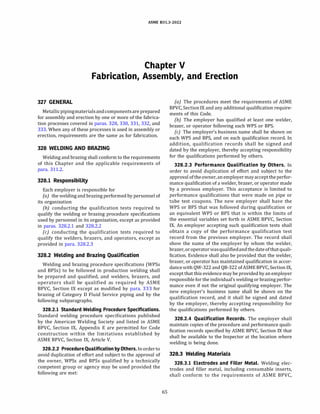
![ASME 831.3-2022
Section II, Part C. An electrode or filler metal not
conforming to the above may be used provided the
WPS and the welders who will follow the WPS have
been qualified as required by ASME BPVC, Section IX.
Unless otherwise specified by the Designer, welding elec
trodesand fillermetalsused shall produceweld metal that
complies with the following:
(a) The nominal tensile strength of the weld metal shall
equal or exceed the minimum specified tensile strength of
the base metals being joined, or the weaker of the two if
base metals of two different strengths are being joined.
{b) The nominal chemical analysis of the weld metal
shall be similar to the nominal chemical analysis of the
major alloying elements of the base metal (e.g., 2%%
Cr, 1% Mo steels should be joined using 2%% Cr, 1%
Mo filler metals).
(c) If base metals of different chemical analysis are
being joined, the nominal chemical analysis of the weld
metal shall be similar to either base metal or an inter
mediate composition, except as specified below for aus
tenitic steels joined to ferritic steels.
(d) When austenitic steels are joined to ferritic steels,
the weld metal shall have a predominantly austenitic
microstructure.
(e) For nonferrous metals, the weld metal shall be that
recommendedbythe manufacturerofthenonferrousbase
metal or by industry associations for that metal.
328.3.2 Weld Backing Material. When backing rings
are used, they shall conform to the following:
(a) Ferrous Metal Backing Rings. These shall be ofweld
able quality. Sulfur content shall not exceed 0.05%.
(b) If two abutting surfaces are to be welded to a third
member used as a backing ring and one or two ofthe three
members are ferritic and the other member or members
are austenitic, the satisfactory use of such materials shall
be demonstrated by welding procedure qualified as
required by para. 328.2.
Backing rings may be of the continuous machined or
split-band type. Some commonly used types are shown in
Figure 328.3.2.
(c) Nonferrous and Nonmetallic Backing Rings. Backing
rings of nonferrous or nonmetallic material may be used,
provided the designer approves their use and the welding
procedure using them is qualified as required by
para. 328.2.
328.3.3 Consumable Inserts.Consumable inserts may
be used, provided they are of the same nominal composi
tion as the filler metal, will not cause detrimental alloying
oftheweld metal, and theweldingprocedureusingthemis
qualified as required by para. 328.2. Some commonly used
types are shown in Figure 328.3.2.
66
328.4 Preparation for Welding
328.4.1 Cleaning. Internal and external surfaces to be
thermally cut or welded shall be clean and free from paint,
oil, rust, scale, and other material that would be detri
mental to either the weld or the base metal when heat
is applied.
328.4.2 End Preparation
(a) General
(1) End preparation is acceptable only if the surface
isreasonably smoothandtrue, and slagfromoxygenorarc
cutting is cleaned from thermally cut surfaces. Discolora
tionremainingonathermallycutsurfaceisnotconsidered
detrimental oxidation.
(2) End preparation for groove welds specified in
ASME 816.25, or any other that meets the WPS, is accept
able. [For convenience, the basic bevel angles of ASME
816.25 and some additional J-bevel angles are shown
in Figure 328.4.2, illustrations (a) and (b).]
{b) Circumferential Welds
(1) if component ends are trimmed as shown in
Figure 328.3.2, illustration (a) or illustration (b) to fit
backing rings or consumable inserts, or as shown in
Figure 328.4.3, illustration (a) or illustration (b) to
correct internal misalignment, such trimming shall not
reduce the finished wall thickness below the required
minimum wall thickness, tm.
(2) Component ends may be bored to allow for a
completely recessed backing ring, provided theremaining
net thickness of the finished ends is not less than tm.
(3) it is permissible to size pipe ends of the same
nominal size to improve alignment if wall thickness re
quirements are maintained.
(4) Where necessary, weld metal may be deposited
inside or outside of the component to permit alignment or
provide for machining to ensure satisfactory seating of
rings or inserts.
(5) When a girth or miter groove weld joins compo
nents of unequal wall thickness and one is more than 11
/2
times the thickness of the other, end preparation and
geometry shall be in accordance with acceptable
designs for unequal wall thickness in ASME 816.25.
(6) Butt-weld fittings manufactured in accordance
with ASME 816.9 may be trimmed to produce an
angular joint offset in their connections to pipe or to
other butt-weld fittings without being subject to design
qualifications in accordance with para. 304.7.2, provided
the total angular offset produced between the two jointed
parts does not exceed 3 deg.](https://image.slidesharecdn.com/26162943-231229160810-282cb07a/85/ASME-B31-3-2022-Procces-piping-code-for-b31-3-93-320.jpg)
![ASME 831.3-2022
Figure 328.3.2
Typical Backing Rings and Consumable Inserts
3mmto5mm
( 1
/s in.to 3t,6 In.)
(al Butt Joint With Bored Pipe Ends
and Solid or Split Backing Ring [Note (11]
3mmto5mm
11/s in.to3/,a in.I
(bl Butt Joint With Teper-Bored Ends
and Solid Backing Ring [Note (1)]
0:8
.·,:.·:. :· ....
(c) Nonmnilllc Remavmi.
Backing Ring (Rffllletory)
(d) Square Ring or Round
Wire Type
�
le) Flat Rectanaui.r Ring
Typical
Consumlble
lnseru
y
(ft Formed Ring Type
(g) Y·Type
NOTE: (1) Refer to ASME 816.25 for detailed dimensional information on welding ends.
+
Figure 328.4.2
Typical Butt Weld End Preparation
37 1/2 deg ± 21
/2 deg 20 deg ± 21/2 deg
T�
y
•
< 22 mm 5mm
-
( 7/
i
-1:_
in.)
�5mm±0.8mm
(1/15 in.± 1/32 in.)
(a) Wall Thickness 6 mm to 22 mm,
Inclusive ( 3t,6 in. to 7/8 in.)
20 deg ± 21
/2 deg
>22 mm
( 7/s in.)
...,_
____._ "",._,,_,..,,_,.��� T.1.<:..£.,LL,�'..£.£.,4,.4.,�
1.5mm± 0.8mm
(1/15 in.±1/32 in.)
(b) Wall Thickness Over 22 mm (7/8 In.)
67
328.4.3 Alignment
(a) Circumferential Welds
(1) Inside surfaces of components at ends to be
joined in girth or miter groove welds shall be aligned
within the dimensional limits in the WPS and the engi
neering design.
(2) Ifthe external surfaces ofthe components are not
aligned, the weld shall be tapered between them.
(b) Longitudinal Welds. Alignment of longitudinal
groove welds (not made in accordance with a standard
listed in Table A-1, Table A-lM, or Table 326.1) shall
conform to the requirements of para. 328.4.3(a).
(c) Branch Connection Welds
(1) Branch connections that abut the outside surface
of the run pipe shall be contoured for groove welds that
meet the WPS requirements [see Figure 328.4.4, illustra
tions (a) and (b)].
(2) Branch connections that are inserted through a
run opening shall be inserted at least as far as the inside
surface of the run pipe at all points [see Figure 328.4.4,
illustration (c)] and shall otherwise conform to para.
328.4.3(c)(1).
(3) Run openings for branch connections shall not
deviate from the required contour more than the dimen
sion min Figure 328.4.4. In no case shall deviations of the
shape of the opening cause the root spacing tolerance](https://image.slidesharecdn.com/26162943-231229160810-282cb07a/85/ASME-B31-3-2022-Procces-piping-code-for-b31-3-94-320.jpg)
![ASME 831.3-2022
Figure 328.4.3
Trimming and Permitted Misalignment
misalignment.
See WPS.
'
'·,�30deg max.
(a) Thicker Pipe Taper-Bored to Align
misalignment.
See WPS.
Round��
corner )--J 30 deg
max.
(b) Thicker Pipe Bored for Alignment
limitsintheWPStobeexceeded.Weldmetalmay beadded
and refinished if necessary for compliance.
{d) Spacing. The root opening of the joint shall be
within the tolerance limits in the WPS.
328.5 Welding Requirements
328.5.1 General
(a) Welds, including addition of weld metal for align
ment [paras. 328.4.2(b)(4) and 328.4.3(c)(3)], shall be
made in accordance with a qualified procedure and by
qualified welders or welding operators.
(b) Eachqualifiedwelderandweldingoperatorshallbe
assignedan identification symbol. Unless otherwise speci
fied in the engineering design, each pressure-containing
weld or adjacent area shall be marked with the identifica
tion symbol of the welder or welding operator. In lieu of
marking the weld, appropriate records shall be filed.
(c) Tackweldsat therootofthe joint shall be madewith
filler metal equivalent to that used in the root pass. Tack
welds shall be made by a qualified welder or welding
operator. Tack welds shall be fused with the root pass
weld, except that those that have cracked shall be
removed. Bridgetacks(above theweld)shallbe removed.
(d) Peening isprohibitedon the root passand final pass
of a weld.
(e) No welding shall be done ifthere is impingement on
the weld area of rain, snow, sleet, or excessive wind, or if
the weld area is frosted or wet.
68
(f) Welding End Valves. The welding sequence and
procedure and any heat treatment for a welding end
valve shall be such as to preserve the seat tightness of
the valve.
328.5.2 Fillet and Socket Welds. Fillet welds (22)
(including socket welds) may vary from convex to
concave. The size of a fillet weld is determined as
shown in Figure 328.S.2A.
(a) For any single continuous fillet weld greater than 5
mm (6 in.), the weld may be less than the specified fillet
weld size by not more than 1.5 mm (6 in.), provided the
total undersized portion of the weld does not exceed 10%
of the total length of the weld or SO mm (2 in.), whichever
is less.
{b) Typical weld details for slip-on and socket welding
flanges are shown in Figure 328.5.28; minimum welding
dimensions for other socket welding components are
shown in Figure 328.S.2C or MSS SP-119.
(c) Ifslip-on flangesare singlewelded, theweldshall be
at the hub.
328.5.3 Seal Welds. Seal welding shall be done by a
qualified welder. Seal welds shall cover all exposed
threads.
328.5.4 Welded Branch Connections
(a) Figures 328.5.4A through 328.S.4F show accept
able details of branch connections with and without
added reinforcement, in which the branch pipe is
connected directly to the run pipe. The illustrations
are typical and are not intended to exclude acceptable
details not shown.
(b) Figure 328.5.40 shows basic types of weld attach
ments used in the fabrication of branch connections. The
location and minimum size of attachment welds shall
conformto the requirementsherein.Weldsshallbe calcu
lated in accordance with para. 304.3.3 but shall be not less
than the sizes shown in Figure 328.5.40. Figure 328.S.4F
shows the basic types of attachment welds used with inte
grally reinforced branch connection fittings. The location
and the minimum size of the attachment welds shall
conform to the requirements of (i) below.
(c) The nomenclature and symbols used herein, in
Figure 328.5.40, and in Figure 328.S.4F are
Tb
nominal thickness of branch
nominal thickness of header
nominal thickness of the branch weld for inte
grally reinforced branch connection fittings
(1) as specified by the manufacturer of the
branch connection fitting
(2) the full depth of the resultant weld
groove, after fit-up, if no manufacturer's weld
thickness is specified
(22)](https://image.slidesharecdn.com/26162943-231229160810-282cb07a/85/ASME-B31-3-2022-Procces-piping-code-for-b31-3-95-320.jpg)
![(al
Legend:
g = root gap per welding specification
m = the lesser of 3.2 mm (1
/8 in.) or 0.5 'fb
ASME 831.3-2022
Figure 328.4.4
Preparation for Branch Connections
(bl
Figure 328.5.2A
Fillet and Socket Weld Sizes
Surface of perpendicular member
vex fillet weld Size of
Surface of perpendicular member
Size of Surface of
weld
weld horizontal member
Theoretical throat ______.,
fillet weld
Surface of
horizontal member
Theoretical throat
(cl
Equal Leg Fillet Weld [Note 11)] Unequal Leg Fillet Weld [Note 12)I
NOTES:
(1) The size of an equal leg fillet weld is the leg length of the largest inscribed isosceles right triangle(theoretical throat= 0.707 x size).
(2) The size of unequal leg fillet weld is the leg lengths of the largest right triangle that can be inscribed within the weld cross section [e.g.,
13 mm x 19 mm(% in. x % in.)].
Figure 328.5.28
Minimum Attachment Weld Dimensions for Double-Welded Slip-On and Socket Welding Flanges
�The lesser of Tor 6 mm ( 1/4 in.)
(al Front and Back Welds (bl Face and Back Welds
Legend:
Xm;n= the lesser of 1.4 'f or the thickness of the hub
69
approx. gap
before welding
(cl Socket Welding Flange](https://image.slidesharecdn.com/26162943-231229160810-282cb07a/85/ASME-B31-3-2022-Procces-piping-code-for-b31-3-96-320.jpg)
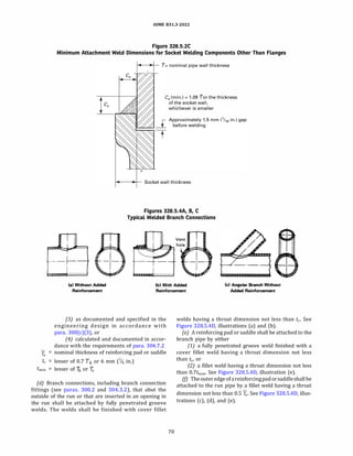
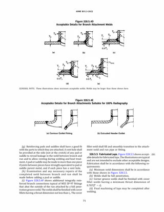
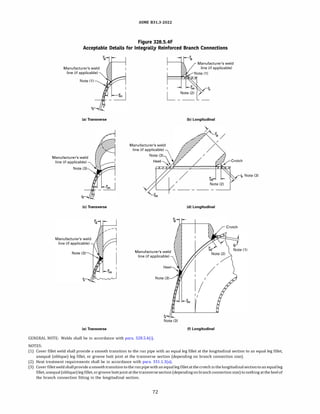
![ASME 831.3-2022
Figure 328.5.5
Typical Details for Fabricated Laps
(a)
Legend:
_j_
T
(b)
c = sum of allowances defined in para. 304.1.1
r = corner radius of fabricated lap
'f = nominal wall thickness of pipe
T2 = minimum thickness of fabricated lap
(e) Welds maybecontouredormachinedtoradius, r, as
in Figure 328.S.S, illustration (e), if necessary, to match
ASME B16.S lapped joint flanges.
328.5.6 Welding for Severe Cyclic Conditions. A
welding procedure shall be employed that provides a
smooth, regular, fully penetrated inner surface.
328.6 Weld Repair
A weld defect to be repaired shall be removed to sound
metal. Repair welds shall be made using a welding proce
dure qualified in accordance with para. 328.2, recognizing
that the cavity to be repaired may differ in contour and
dimensions from the original joint. Repair welds shall be
made by welders or welding operators qualified in accor
dance with para. 328.2. Preheating and heat treatment
shall be as required for the original welding. See also
para. 341.3.3.
(22) 328.7 Attachment Welds
The welding of structural and other non-pressure
retaining attachments may bemadeby complete penetra
tion, partial penetration, fillet, or stud welding.
For temporary attachments on pressure-retaining
components, the surfaces where attachments have
been removed shall be finished by grinding or other ac
ceptable means. Surfaces shall be blended smoothly into
the surrounding base metal without encroaching on the
minimum required thickness, tm, and examined. See
para. 341.4 for the extent of required examinations.
Low energy capacitor discharge welding may be used
for welding thermocouples or strain gages without
preheat above 10°
C (50°
F) or subsequent postweld
heat treatment on P-No. 1 through P-No. SB and P-No.
lSE materials, provided
(c)
73
(d)
J_
T t--
1
(e)
(a) a Welding Procedure Specification is prepared,
describing the low energy capacitor discharge equipment,
the combination of materials to be joined, and the tech
nique of application; qualification of the welding proce
dure is not required
(b) the energy output of the welding process is limited
to 125 W-sec
(c) for P-No. SA, P-No. SB, and P-No. lSE materials, the
maximum carbon content of the material is 0.15%
{d) after thermocouples or strain gages are removed,
the areas shall be examined in accordance with
para. 341.4.
330 PREHEATING
330.1 General
The preheat requirements herein apply to all types of
welding, includingtackwelds, repairwelds, andsealwelds
on threaded joints.
The preheating rules in ASME B31P may be used as an
alternate.
330.1.1 Requirements. Unless specified otherwise in
the engineering design, the minimum preheat tempera
tures for materials of various P-Numbers are given in
Table 330.1.1. The thickness intended in Table 330.1.1
is that of the nominal thickness of the thicker component
[as defined in para. 331.1.3(c)]. Higher minimum preheat
temperatures may be required by the WPS or by the engi
neering design.
330.1.2 Unlisted Materials. Preheat requirements for
an unlisted material shall be specified in the WPS.
(22)](https://image.slidesharecdn.com/26162943-231229160810-282cb07a/85/ASME-B31-3-2022-Procces-piping-code-for-b31-3-100-320.jpg)
![ASME 831.3-2022
Table 330.1.1
Preheat Temperatures
Greater Material
Base Metal P-No. Thickness Additional Limits Required Minimum Temperature
[Note (1}] Base Metal Group mm in. [Note (2}] oc OF
1 Carbon steel s25 sl None 10 so
>25 >l %C s 0.30 [Note (3)] 10 so
>25 >l %C > 0.30 [Note (3)] 95 200
3 Alloy steel, Cr s 1/z% $13 $
1
/2 SMTS s 450 MPa (65 ksi) 10 so
>13 >1
/2 SMTS s 450 MPa (65 ksi) 95 200
All All SMTS > 450 MPa (65 ksi) 95 200
4 Alloy steel, 1/z% < Cr All All None 120 250
s 2%
SA Alloy steel All All SMTS s 414 MPa (60 ksi) 150 300
All All SMTS > 414 MPa (60 ksi) 200 400
SB Alloy steel All All SMTS s 414 MPa (60 ksi) 150 300
All All SMTS > 414 MPa (60 ksi) 200 400
>13 >'l2 %Cr > 6.0 [Note (3)] 200 400
6 Martensitic stainless All All None 200 [Note (4)] 400 [Note (4)]
steel
9A Nickel alloy steel All All None 120 250
9B Nickel alloy steel All All None 150 300
101 27Cr steel All All None 150 [Note (S)] 300 [Note (S)]
lSE 9Cr-1Mo-V CSEF All All None 200 400
steel
All other materials None 10 so
NOTES:
(1) P-Nos. and Group Nos. from ASME BPVC, Section IX, Table QW/QB-422.
(2) SMTS = Specified Minimum Tensile Strength.
(3) Composition may be based on ladle or product analysis or in accordance with specification limits.
(4) Maximum interpass temperature 315°
C (600°
F).
(5) Maintain interpass temperature between 150°
C and 230°
C (300°
F and 450°
F).
74](https://image.slidesharecdn.com/26162943-231229160810-282cb07a/85/ASME-B31-3-2022-Procces-piping-code-for-b31-3-101-320.jpg)
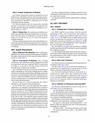
![P-No. and Group No.
(ASME BPVC, Section IX, QW/QB-420)
P-No. 1, Group Nos. 1-3
P-No. 3, Group Nos. 1 and 2
P-No. 4, Group Nos. 1 and 2
P-No. SA, Group No. 1
P-No. SB, Group No. 1
ASME 831.3-2022
Table 331.1.1
Postweld Heat Treatment
Holding Temperature Range,
�C (°
F) [Note (1)]
595 to 650 (1,100 to 1,200)
595 to 650 (1,100 to 1,200)
650 to 705 (1,200 to 1,300)
675 to 760 (1,250 to 1,400)
675 to 760 (1,250 to 1,400)
P-No. 6, Group Nos. 1-3 760 to 800 (1,400 to 1,475)
P-No. 7, Group Nos. 1 and 2 (Note (3)] 730 to 775 (1,350 to 1,425)
P-No. 8, Group Nos. 1-4
P-No. 9A, Group No. 1
P-No. 98, Group No. 1
P-No. lOH, Group No. 1
P-No. 101, Group No. 1 [Note (3)]
P-No. llA
P-No. lSE, Group No. 1
P-No. 62
All other materials
PWHT not required unless required by WPS
595 to 650 (1,100 to 1,200)
595 to 650 (1,100 to 1,200)
PWHT not required unless required by
WPS. If done, see Note (4).
730 to 815 (1,350 to 1,500)
550 to 585 (1,025 to 1,085) (Note (5)]
705 to 775 (1,300 to 1,425)
(Notes (6), (7)]
540 to 595 (1,000 to 1,100)
PWHT as required by WPS
GENERAL NOTE: The exemptions for mandatory PWHT are defined in Table 331.1.3.
NOTES:
Minimum Holding Time at Temperature for
Control Thickness [Note (2)]
Up to 50 mm (2 in.) Over 50 mm (2 in.)
1 h/25 mm (1 hr/in.); 2 hr plus 15 min for each
15 min min. additional 25 mm (in.)
over 50 mm (2 in.)
1 h/25 mm (1 hr/in.);
30 min min.
1 h/25 mm (1 hr/in.) up
to 125 mm (5 in.) plus
15 min for each
additional 25 mm (in.)
over 125 mm (5 in.)
See Note (8)
In accordance with WPS In accordance with WPS
(1) The holding temperature range is further defined in para. 331.l.6(c) and Table 331.1.2.
(2) The control thickness is defined in para. 331.1.3.
(3) Cooling rate shall not be greater than 55°
C (100°
F) per hour in the range above 650°
C (1,200°
F), after which the cooling rate shall be
sufficiently rapid to prevent embrittlement.
(4) If PWHT is performed after welding, it shall be within the following temperature ranges for the specific alloy, followed by rapid cooling:
Alloys S31803 and S32205 - 1020°
C to 1100°
C (1,870°
F to 2,010°
F)
Alloy S32550 - 1040°
C to 1120°
C (1,900°
F to 2,050°
F)
Alloy S32750 - 1025°
C to 1125°
C (1,880°
F to 2,060°
F)
All others - 980°
C to 1040°
C (1,800°
F to 1,900°
F)
(5) Cooling rate shall be >165°
C (>300°
F)/h to 315°
C (600°
F)/h.
(6) Theminimum PWHT holding temperature may be 675°
C (1,250°
F) for nominal material thicknesses [see para. 331.l.3(c)] ,;;13 mm (,;;Y2 in.).
(7) The Ni+ Mn content of the filler metal shall not exceed 1.2% unless specified by the designer, in which case the maximum temperature to be
reached during PWHT shall be the lower transformation temperature of the filler metal, as determined by analysis and calculation or by test,
but not exceeding 800°
C (1,470°
F). If the800°
C (1,470°
F)limit was not exceededbut thelower transformation temperatureofthe fillermetal
was exceeded or if the composition of the filler metal is unknown, the weld must be removed and replaced. It shall then be rewelded with
compliant filler metal and subjected to a compliant PWHT. If the800°
C (1,470°
F) limit was exceeded, the weld and the entire area affected by
the PWHT will be removed and, if reused, shall be renormalized and tempered prior toreinstallation.The lowertransformationtemperature
is the steady-state temperature at which the austenite phase transformation occurs.
(8) Heattreat within14 days afterwelding. Holdtimeshall beincreased by1.2hforeach25 mm (1in.)over25 mm (1in.)thickness. Coolto425°
C
(800°
F) at a rate $280°
C (,;;500°
F)/h.
76](https://image.slidesharecdn.com/26162943-231229160810-282cb07a/85/ASME-B31-3-2022-Procces-piping-code-for-b31-3-103-320.jpg)
![ASME 831.3-2022
Table 331.1.2
Alternate Postweld Heat Treatment Requirements
for Carbon and Low Alloy Steels, P-Nos. I and 3
Decrease in Specified Minimum
Temperature, °
C (°
F)
30 (50)
55 (100)
85 (150) (Note (2)]
110 (200) (Note (2)]
NOTES:
Minimum Holding Time at
Decreased Temperature,
h [Note (1)]
2
4
10
20
(1) Times shown apply to thicknesses :525 mm (:51 in.). Add 15 min/
25 mm (15 min/in.)ofthickness for control thicknesses >25 mm
(>l in.) (see para. 331.1.3).
(2) A decrease >55°
C (>100°
F) below the minimum specified
temperature is allowable only for P-No. 1, Group Nos. 1 and 2
materials.
77](https://image.slidesharecdn.com/26162943-231229160810-282cb07a/85/ASME-B31-3-2022-Procces-piping-code-for-b31-3-104-320.jpg)
![P-No. and Group No.
(ASME BPVC, Section IX,
Table QW/QB-420)
[Note (1)]
P-No. 1, all Group Nos.
P-No. 3, Group Nos. 1 and 2
P-No. 4, Group No. 1
P-No. SA, Group No. 1
P-No. SB, Group No. 1
ASME 831.3-2022
Table 331.1.3
Exemptions to Mandatory Postweld Heat Treatment
All
Control Thickness,
mm (in.) [Note (2)]
s16 mm (s% in.)
s16 mm (s% in.)
Type of Weld
All
All
Groove
s16 mm (s% in.) except Socket and fillet welds
the thickness of a
socket weld fitting or
flange need not be
considered
s16 mm (s% in.)
s16 mm (s% in.)
Seal welds and
non-load-carrying
attachments [Note (7)]
Groove
s16 mm (s% in.) except Socket and fillet welds
the thickness of a
socket weld fitting or
flange need not be
considered
s16 mm (s% in.) Seal welds and
non-load-carrying
attachments [Note (7)]
78
Additional Limitations Required for
Exemption From PWHT [Notes (3)-(5)]
A preheat of 95°
C (200°
F) is applied prior to
welding on any nominal material thickness
>25 mm (>1 in.)
Multiple layer welds are used when the nominal
material thickness >5 mm (>3
/16 in.) [Note (6)]
A preheat of 95°
C (200°
F) is applied prior to
welding on any nominal material thickness
>13 mm (>1
/2 in.)
A specified carbon content of the base materials
s0.25%
Multiple layer welds are used when the nominal
material thickness >5 mm (>3
/16 in.) [Note (6)]
Mandatory preheat has been applied
Specified carbon content of the base materials
s0.15%
Multiple layer welds are used when the nominal
material thickness >5 mm (>3/i6 in.) [Note (6)]
Mandatory preheat has been applied
Throat thickness of the fillet weld or the socket
weld s13 mm (s1
/2 in.)
Specified carbon content of the pipe material
s0.15%
Nominal material thickness of the pipe s16 mm
(s% in.)
Multiple layer welds are used when the nominal
material thickness >5 mm (>3
/16 in.) [Note (6)]
Mandatory preheat has been applied
Multiple layer welds are used when the nominal
material thickness >5 mm (>3/i6 in.) [Note (6)]
Mandatory preheat has been applied
Specified carbon content of the base materials
s0.15%
Multiple layer welds are used when the nominal
material thickness >5 mm (>3/i6 in.) [Note (6)]
Mandatory preheat has been applied
Throat thickness of the fillet weld or the socket
weld s13 mm (s1
/2 in.)
Specified carbon content of the pipe material
s0.15%
Nominal thickness of the pipe sS mm (s3/i6 in.)
Multiple layer welds are used when the nominal
material thickness >5 mm (>3
/16 in.) [Note (6)]
Mandatory preheat has been applied
Multiple layer welds are used when the nominal
material thickness >5 mm (>3
/16 in.) [Note (6)]
No exemptions from PWHT](https://image.slidesharecdn.com/26162943-231229160810-282cb07a/85/ASME-B31-3-2022-Procces-piping-code-for-b31-3-105-320.jpg)
![ASME 831.3-2022
Table 331.1.3
Exemptions to Mandatory Postweld Heat Treatment (Cont'd)
P-No. and Group No.
(ASME BPVC, Section IX,
Table QW/QB-420)
[Note (1)]
P-No. 6, Group Nos. 1-3
P-No. 7, Group No. 1
P-No. 7, Group No. 2
P-No. 8, all Group Nos.
P-No. 9A, Group No. 1
P-No. 98, Group No. 1
P-No. lOH, Group No. 1
P-No. 101, Group No. 1
P-No. 11A
P-No. 15E
P-No. 62
NOTES:
Control Thickness,
mm (in.) [Note (2)]
All
All
All
All
All
All
All
$50 mm ($2 in.)
Type of Weld
All
All
All
All
All
All
All
All
Additional Limitations Required for
Exemption From PWHT [Notes (3)-(5)]
Specified carbon content of the base materials
$0.08%
Nominal material thickness $10 mm ($% in.)
Weld filler metal is A-No. 8, A-No. 9, or F-No. 43
composition [Note (8)]
Specified carbon content of the base materials
$0.08%
Nominal material thickness $10 mm ($% in.)
Weld filler metal is A-No. 8, A-No. 9, or
F-No. 43 composition [Note (8)]
No exemptions from PWHT
PWHT neither required nor prohibited
Specified carbon content of the pipe material
$0.15%
Nominal material thickness $13 mm ($1/z in.)
Mandatory preheat has been applied
Nominal material thickness $16 mm ($% in.) and
the WPS has been qualified using a material
of equal or greater thickness than used in the
production weld
PWHT neither required nor prohibited
PWHT neither required nor prohibited for
nominal material thickness $13 mm ($'l2 in.)
No exemptions from PWHT
No exemptions from PWHT
(1) If differences with the P-No. listed in Appendix A are found, the P-No. listed in ASME BPVC, Section IX, Table QW/QB-422 applies.
(2) The control thickness is defined in para. 331.1.3.
(3) The nominal material thickness is defined in para. 331.1.3(c).
(4) No exemptions are permitted for PWHTs required by the designer or the WPS.
(5) Additional exemptions for welds made in accordance with para. 328.7 may be taken for the materials addressed.
(6) Single-layer orsingle-passweldsmaybeexemptedfromPWHT, provided the WPS hasbeen qualifiedusingsingle-passweldswith ±10% heat
input and that all other conditions for exemption are met.
(7) Non-load-carrying attachments are defined as items where no pressure loads or significant mechanical loads are transmitted through the
attachment to the pipe or pressure-containing material.
(8) The A-Nos. and the F-Nos. are found in ASME BPVC, Section IX, Tables QW-442 and QW-432, respectively.
79](https://image.slidesharecdn.com/26162943-231229160810-282cb07a/85/ASME-B31-3-2022-Procces-piping-code-for-b31-3-106-320.jpg)
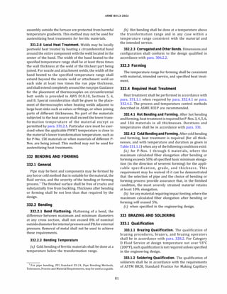
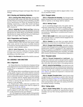
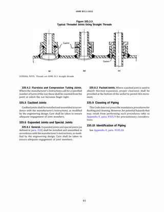
![ASME 831.3-2022
Chapter VI
Inspection, Examination, and Testing
340 INSPECTION
340.1 General
This Code distinguishes between examination (see
para. 341) and inspection. Inspection applies to functions
performed for the owner by the owner's Inspector or the
Inspector's delegates. References in this Code to the
"Inspector" aretotheowner's Inspector or theInspector's
delegates.
340.2 Responsibility for Inspection
It is the owner's responsibility, exercised through the
owner'sInspector, toverify that all required examinations
and testing have been completed and to inspect the piping
to the extent necessary to be satisfied that it conforms to
all applicable examination requirements of the Code and
of the engineering design.
(22) 340.3 Rights of the Owner's Inspector
The owner's Inspector and the Inspector's delegates
shall have access to any place where work concerned
with the piping installation is being performed. This
includes manufacture, fabrication, heat treatment,
assembly, erection, examination, and testing of the
piping. They shall havetheright to audit any examination,
to inspect the piping, to perform examinations using any
method specified by the engineering design, and to review
all certifications and records necessary to satisfy the
owner's responsibility stated in para. 340.2.
340.4 Qualifications of the Owner's Inspector
(a) The owner's Inspector shall be designated by the
owner and shall be the owner, an employee of the owner,
an employee of an engineering or scientific organization,
or the employee of a recognized insurance or inspection
company acting as the owner's agent. The owner's
Inspector shall not represent nor be an employee of
the piping manufacturer, fabricator, or erector unless
the owner isalso the manufacturer, fabricator, or erector.
{b) The owner's Inspector shall meet one of the
following requirements:
(1) have at least 10 yr of experience in the design,
fabrication, or examination of industrial pressure piping.
Each 20% of satisfactorily completed work toward an ac-
84
credited engineering degree shall be considered equiva
lent to 1 yr of experience, up to 5 yr total.
(2) have a professional engineering registration or
nationally recognized equivalent with at least 5 yr of
experience in the design, fabrication, or examination of
industrial pressure piping.
(3) be a certified welding inspector or a senior certi
fied welding inspector as defined in AWS QCl, Specifica
tion for AWS Certification of Welding Inspectors, or
nationally recognized equivalent with at least 5 yr of
experience in the design, fabrication, or examination of
industrial pressure piping.
(4) be an authorized piping inspector as defined in
AP! 570, Piping Inspection Code: In-service Inspection,
Rating, Repair, and Alteration of Piping Systems, with
at least 5 yr of experience in the design, fabrication, or
examination of industrial pressure piping.
(c) In delegating performance of inspection, the
owner's Inspector is responsible for determining that a
person to whom an inspection function is delegated is
qualified to perform that function.
341 EXAMINATION
341.1 General
Examination applies to quality control functions
performed by the manufacturer (for components only),
fabricator, or erector. Reference in this Code to an exam
iner is to a person who performs quality control examina
tions.
341.2 Responsibility for Examination
Inspectiondoes not relieve the manufacturer, the fabri
cator, or the erector of the responsibility for
(a) providing materials, components, and workman
ship in accordance with the requirements of this Code
and of the engineering design [see para. 300(b)(3)]
(b) performing all required examinations
(c) preparing suitable records of examinations and
tests for the Inspector's use
341.3 Examination Requirements
341.3.1 General. Prior to initial operation, each piping (22)
installation, including components and workmanship,
shall be examined in accordance with the applicable](https://image.slidesharecdn.com/26162943-231229160810-282cb07a/85/ASME-B31-3-2022-Procces-piping-code-for-b31-3-111-320.jpg)
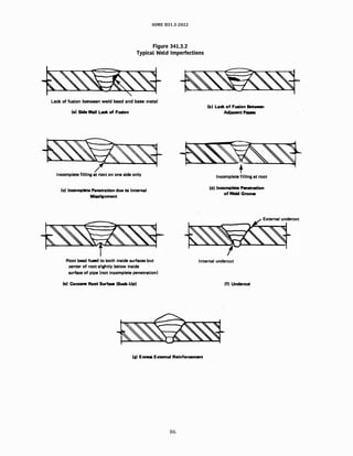
![a:)
-..J
Table
341.3.2
Acceptance
Criteria
for
Welds
-
Visual
and
Radiographic
Examination
Criteria
(A
to
M)
for
Types
of
Welds
and
for
Service
Conditions
[Note
(1)]
Normal
and
Category
M
Fluid
Service
Severe
Cyclic
Conditions
Category
D
Fluid
Service
Examination
Methods
Girth,
Girth,
Miter
Miter
Groove,
and
Groove,
and
Girth
Branch
Longitudinal
Branch
and
Branch
Connection
Groove
Fillet
Connection
Longitudinal
Fillet
Miter
Longitudinal
Fillet
Connection
Welds
Weld
Weld
Welds
Groove
Weld
Weld
Groove
Groove
Weld
Weld
Weld
[Note
(2)]
[Note
(3)1
[Note
(4)]
[Note
(2)1
[Note
(3)]
[Note
(4)]
Welds
[Note
(3)]
[Note
(4)]
[Note
(2)]
Imperfection
Visual
Radiography
A
A
A
A
A
A
A
A
A
A
Crack
./
./
A
A
A
A
A
A
c
A
N/A
A
Lack
of
fusion
./
./
B
A
N/A
A
A
N/A
c
A
N/A
B
Incomplete
penetration
./
./
E
E
N/A
D
D
N/A
N/A
N/A
N/A
N/A
Rounded
Indications
...
./
G
G
N/A
F
F
N/A
N/A
N/A
N/A
N/A
Linear
indications
...
./
H
A
H
A
A
A
I
A
H
H
Undercutting
./
./
A
A
A
A
A
A
A
A
A
A
Surface
porosity
or
exposed
slag
./
...
inclusion
[Note
(SJ]
N/A
N/A
N/A
J
J
J
N/A
N/A
N/A
N/A
Surface
finish
./
...
K
K
N/A
K
K
N/A
K
K
N/A
K
Concave
surface,
concave
root
./
./
surface,
or
burn-through
L
L
L
L
L
L
M
M
M
M
Face
reinforcement
or
root
rein-
./
...
forcement
GENERAL
NOTES:
(a)
Imperfections
are
evaluated
by
one
or
more
of
the
examination
methods
given,
as
specified
in
paras.
341.4.1,
341.4.2,
341.4.3,
and
M341.4,
or
by
the
engineering
design.
(b)
"N/A"
indicates
the
Code
does
not
establish
acceptance
criteria
or
does
not
require
evaluation
of
this
kind
of
imperfection
for
this
type
of
weld.
(c)
Check(./)
indicates
examination
method
generally
used
for
evaluating
this
kind
of
imperfection.
(d)
Ellipsis
(
...
)
indicates
examination
method
not
generally
used
for
evaluating
this
kind
of
imperfection.
NOTES:
(1)
Criteria
given
are
for
required
examination.
More-stringent
criteria
may
be
specified
in
the
engineering
design.
See
also
paras.
341.5
and
341.5.3.
(2)
Branch
connection
weld
includes
pressure
containing
welds
in
branches
and
fabricated
laps.
(3)
Longitudinal
groove
weld
includes
straight
and
spiral
(helical)
seam.
Criteria
are
not
intended
to
apply
to
welds
made
in
accordance
with
a
standard
listed
in
Table
A-1,
Table
A-lM,
or
Table
326.1.
Alternative
Leak
Test
requires
examination
of
these
welds;
see
para.
345.9.
(4)
Fillet
weld
includes
socket
and
seal
welds,
and
attachment
welds
for
slip-on
flanges,
branch
reinforcement,
and
supports.
(SJ
These
imperfections
are
evaluated
only
for
welds
,;;5
mm
(,;;3/i
6
in.)
in
nominal
thickness.
(22)
>
"'
tTl
t:ll
w
......
w
.:..,
0
N
N](https://image.slidesharecdn.com/26162943-231229160810-282cb07a/85/ASME-B31-3-2022-Procces-piping-code-for-b31-3-114-320.jpg)
![(22)
00
00
NOTES:
Symbol
A
B
c
D
E
F
G
H
K
L
M
Criterion
Value
Notes
for
Table
341.3.2
Criterion
Measure
Extent
of
imperfection
Cumulative
length
of
incomplete
penetration
Cumulative
length
of
lack
of
fusion
and
incomplete
penetration
Size
and
distribution
of
rounded
indications
Size
and
distribution
of
rounded
indications
Linear
indications
Individual
length
Individual
width
Cumulative
length
Linear
indications
Individual
length
Individual
width
Cumulative
length
Depth
of
undercut
Cumulative
length
of
internal
and
external
undercut
Depth
of
undercut
Cumulative
length
of
internal
and
external
undercut
Surface
roughness
Depth
of
surface
concavity,
root
surface
concavity,
or
burn-through
Height
of
face
reinforcement
or
root
reinforcement
(Note
(5)]
in
any
plane
through
the
weld
shall
be
within
limits
of
the
applicable
height
value
in
the
tabulation
at
right,
except
as
provided
in
Note
(6).
Weld
metal
shall
merge
smoothly
into
the
component
surfaces.
Height
of
face
reinforcement
or
root
reinforcement
(Note
(5)]
as
described
in
L.
Note
(6)
does
not
apply.
Acceptable
Value
Limits
[Note
(1))
Zero
(no
evident
imperfection)
s38
mm
(sl.5
in.)
in
any
150
mm
(6
in.)
weld
length
or
25%
of
total
weld
length,
whichever
is
less
s38
mm
(sl.5
in.)
in
any
150
mm
(6
in.)
weld
length
or
25%
of
total
weld
length,
whichever
is
less
See
ASME
BPVC,
Section
VIII,
Division
1,
Appendix
4
[Note
(2)]
For
fw
s
6
mm
(%
in.),
limit
is
same
as
D
(Note
(2)]
For
fw
>
6mm
(1;
4
in.),
limit
is
1.5
x
D
(Note
(2)]
sfw/
3
s2.5
mm
(s%
2
in.)
and
sfw/
3
sfw
in
any
12
fw
weld
length
(Note
(2)]
s2fw
s3
mm
(s'ls
in.)
and
sfw/2
s4fw
in
any
150
mm
(6
in.)
weld
length
or
8%
of
total
weld
length,
whichever
is
less
(Note
(2)]
sl
mm
(s%
2
in.)
and
sfw/4
s38
mm
(sl.5
in.)
in
any
150
mm
(6
in.)
weld
length
or
25%
of
total
weld
length,
whichever
is
less
sl.5
mm
(s
1
/
16
in.)
and
s[T,v/4
or
1
mm
(%
2
in.)]
s38
mm
(sl.5
in.)
in
any
150
mm
(6
in.)
weld
length
or
25%
of
total
weld
length,
whichever
is
less
s12.5
µm
(s500
µin.)
R
a
in
accordance
with
ASME
846.1
Total
joint
thickness,
including
weld
reinforcement,
::C:fw
(Notes
(3),
(4)]
fw,
mm
(in.)
s6
(s%)
>6
(>%),
s13
(s
1
/
2
)
>13
(>1/z),
s25
(sl)
>25
(>l)
Limit
is
twice
the
value
applicable
for
L
above
Height,
mm
(in.)
sl.5
(s
1
/
16
)
s3
(s'ls)
s4
(s
%
2
)
s5
(s
6
)
(1)
Where
two
limiting
values
are
separated
by
"and;'
the
lesser
of
the
values
determines
acceptance.
Where
two
sets
of
values
are
separated
by
"or,"
the
larger
value
is
acceptable.
fw
is
the
nominal
wall
thickness
of
the
thinner
of
two
components
joined
by
a
butt
weld.
>
"'
!:Tl
0::,
w
....
w
N
0
N
N](https://image.slidesharecdn.com/26162943-231229160810-282cb07a/85/ASME-B31-3-2022-Procces-piping-code-for-b31-3-115-320.jpg)
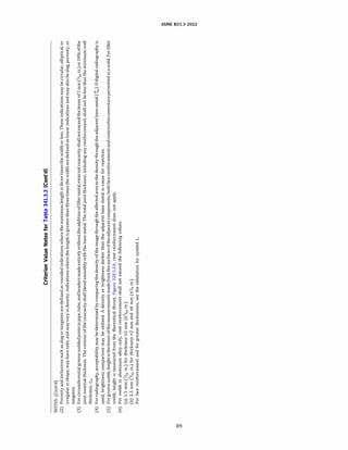
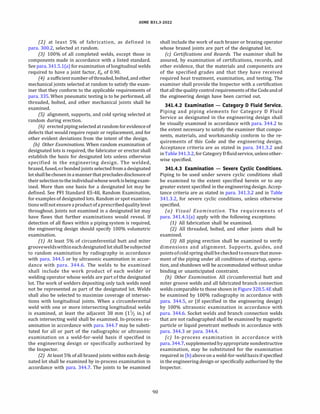
![ASME 831.3-2022
(a) At theowner'soption, apipingsystem in Category D
fluid service may be subjected to an initial service leak test
in accordance with para. 345.7, in lieu of the hydrostatic
leak test.
(b) Where the owner considers a hydrostatic leak test
impracticable, either a pneumatic test in accordance with
para. 345.5 or a combined hydrostatic-pneumatic test in
accordance with para. 345.6 may be substituted, recog
nizing the hazard of energy stored in compressed gas.
(c) Where the owner considers both hydrostatic and
pneumatic leak testing impracticable, the alternative
specifiedinpara.345.9maybeusedifbothofthe following
conditions apply:
(1) a hydrostatic test would
(-a) damage linings or internal insulation or
(-b) contaminate a process that would be hazard
ous, corrosive, or inoperative in the presence of moisture
or
(-c) require significant support modifications for
the hydrostatic test load or
(-d) present the danger of brittle fracture due to
low metal temperature during the test
(2) a pneumatic test would
(-a) present an undue hazard ofpossible release of
energy stored in the system or
(-b) present the danger of brittle fracture due to
low metal temperature during the test
(d} Unless specified in the engineering design, lines
open to the atmosphere, such as vents or drains down
stream of the last shutoff valve, need not be leak tested.
345.2 General Requirements for Leak Tests
Requirements in para. 345.2 apply to more than one
type of leak test.
345.2.1 Limitations on Pressure
(a) Reduced Test Pressure. If the test pressure would
produce a circumferential or longitudinal stress (based
on minimum pipe wall thickness) in excess of yield
strength at test temperature or is greater than 1.5
times the component rating at test temperature, the
test pressure may be reduced to the maximum pressure
that will not exceed the lesser of the yield strength or 1.5
times a component rating at test temperature. [See
para. 302.3.2.] For metallic bellows expansion joints,
see Appendix X, para. X302.2.3(a).
{bJ Test FluidExpansion. If a pressure test is to be main
tained foraperiodoftimeandthetest fluidinthesystemis
subject to thermal expansion, precautionsshall betakento
avoid excessive pressure.
(c) Preliminary Pneumatic Test. A preliminary test
using air at no more than 170 kPa (25 psi) gage pressure
may be made prior to hydrostatic testing to locate major
leaks.
94
345.2.2 Other Test Requirements (22)
(a) Examinationfor Leaks. The leak test pressure shall
be maintained for at least 10 min and then all joints and
connections shall be examined for leaks. The test pressure
may be reduced to not less than the design pressure while
performing this examination.
(bJ Heat Treatment. Leak tests shall be conducted after
any heat treatment has been completed.
(cJ Low Test Temperature. Thepossibilityofbrittlefrac
ture shall be considered when conducting leak tests at
metal temperatures near the ductile-brittle transition
temperature.
(d} Test Gages
(1) One or more pressure-indicating gages shall be
connected to the piping in a manner in which they will
receive full test pressure.
(2) Dial indicating pressure gages used in leak
testing should be graduated over a range of about
double the intended test pressure, but in no case shall
the range be less than 1Vz nor more than 4 times the
test pressure.
(3) Digital reading pressure gages having a wider
range of pressure may be used, provided the readings
give the same or greater degree of accuracy as obtained
with dial pressure gages.
(4) The level of accuracy for pressure test gages
should be specified in the engineering design.
(5) Each gage shall be calibrated against a standard
dead weight tester or a calibrated master gage. The gage
shall have been calibrated within 12 months prior to each
test, or any time there is reason to believe the gage is in
error. Calibration may exceed 12 months with owner's
approval.
345.2.3 Special Provisions for Testing
(a) Piping Components and Subassemb/ies. Piping
componentsandsubassembliesmaybetestedeithersepa
rately or as assembled piping.
(bJ Flangedjoints. Flangedjointsusedtoconnectpiping
componentsand subassemblies that have previously been
tested, and flanged joints at which a blank or blind is used
toisolateequipmentorother pipingduringatest, neednot
be leak tested in accordance with para. 345.1.
(c) Closure Welds. The final weld connecting piping
systems or components that have been successfully
tested in accordance with para. 345 need not be leak
tested provided theweldis examined in-process in accor
dance with para. 344.7 and passes with 100% radio
graphic examination in accordance with para. 344.5 or
100% ultrasonic examination in accordance with para.
344.6.
(d) Instrument Connections. Threaded joints, tubing
joints, or a combination of these joints used to connect
instruments to previously leak tested piping need not
be leak tested in accordance with para. 345.1.
(e) See also Appendix F, para. F345.2.3.](https://image.slidesharecdn.com/26162943-231229160810-282cb07a/85/ASME-B31-3-2022-Procces-piping-code-for-b31-3-121-320.jpg)
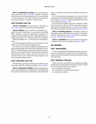
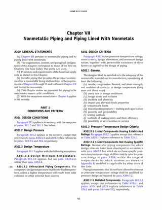
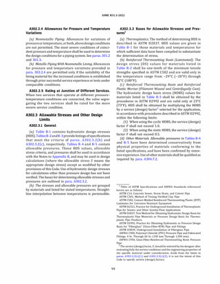
![ASME 831.3-2022
(a) Thermoplastic Pipe [see para. A302.3.2(a)]
PD
t = --(Table B-1) (26a)
2S + P
{b) RTR {Laminated) Pipe [see para. A302.3.2(b)]3
PD
t = --(Table B-2)
2S + P
(26b)
(c) RTR {Filament Wound) and RPM (Centrifugally Cast)
Pipe [see para. A302.3.2(c)]3
PD
t = (Table B-3)
2SF+ P
(26c)
A304.l.3 Straight Pipe Under External Pressure
(a) Nonmetallic Pipe. The external pressure design
thickness, t, shall be qualified as required by
para. A304.7.2.
{b) Metallic Pipe Lined With Nonmetals
(1) The external pressure designthickness, t, for the
base (outer) material shall be determined in accordance
with para. 304.1.3.
(2) The external pressure design thickness, t, for the
lining material shall be qualified as required by
para. A304.7.2.
A304.2 Curved and Mitered Segments of Pipe
A304.2.l Pipe Bends. The minimum required thick
ness, tm, of a bend, after bending, shall be determined
as for straight pipe in accordance with para. A304.l.
A304.2.2 Elbows. Manufactured elbows not in accor
dance with para. A303 shall be qualified as required by
para. A304.7.2.
A304.2.3 Miter Bends. Miter bendsshall be qualifiedas
required by para. A304.7.2.
A304.3 Branch Connections
A304.3.l General.Apipehavingabranchconnectionis
weakened by the opening that must be made in it and,
unless the wall thickness of the pipe is sufficiently in
excess of that required to sustain the pressure, it is nec
essary to provide added reinforcement. The amount of
reinforcement shall be qualified as required by
para. A304.7.2 except as provided in para. A304.3.2.
A304.3.2 Branch Connections Using Fittings. It may
be assumed without calculation that a branch connection
has adequate strength to sustain the internal and external
pressurethat will beapplied toitifitutilizesafitting(atee,
lateral, or cross) in accordance with para. A303.
3 The internal design pressure thickness, t, shall not include any thick
ness of the pipe wall reinforced with less than 20% by weight of reinfor
cing fibers.
101
A304.3.3 Additional Design Considerations. The re
quirements of paras. A304.3.1 and A304.3.2 are intended
toassuresatisfactoryperformanceofa branch connection
subjected only to internal or external pressure. The
designer shall also consider paras. 304.3.S(a),
304.3.S(c), and 304.3.S(d).
A304.4 Closures
Closures not in accordance with para. A303 shall be
qualified as required by para. A304.7.2.
A304.5 Pressure Design of Nonmetallic Flanges
A304.5.l General
(a) Flanges not in accordance with (b), (d), or para.
A303 shall be qualified as required by para. A304.7.2.
(b) Flanges for use with flat ring gaskets may be
designed in accordance with ASME BPVC, Section Vlll,
Division 1, Appendix 2, except that the allowable stresses
and temperature limits of this Code shall govern. Nomen
clature shall be as defined in ASME BPVC, except for the
following:
P = design gage pressure
Sa = bolt design stress at atmospheric temperature4
Sh = bolt design stress at design temperature4
s1 = allowable stress for flange material from
Table B-1, Table B-2, or Table B-3
(c) The rules in (b)aboveare not applicable toa flanged
joint having a gasket that extends outside the bolts
(usually to the outside diameter of the flange).
(d} For flanges that make solid contact outside the
bolts, ASME BPVC, Section Vlll, Division 1, Appendix Y
should be used.
A304.5.2 Blind Flanges. Blind flanges not in accor
dance with para. A303 may be designed in accordance
with para. 304.5.2, except that allowable stress, S, shall
be taken from tables in Appendix B. Otherwise, they
shall be qualified as required by para. A304.7.2.
A304.6 Reducers
Reducers not in accordance with para. A303 shall be
qualified as required by para. A304.7.2.
A304.7 Pressure Design of Other Components
A304.7.l Listed Components. Other pressure
containing components, manufactured in accordance
withstandards inTableA326.1butnotcovered elsewhere
in para. A304, may be utilized in accordance with para.
A303.
A304.7.2 Unlisted Components. Pressure design of
unlisted components and joints, to which the rules else
where in para. A304 do not apply, shall be based on
4 Boltdesignstressesshall notexceedthosein TableA-2 orTableA-2M.](https://image.slidesharecdn.com/26162943-231229160810-282cb07a/85/ASME-B31-3-2022-Procces-piping-code-for-b31-3-128-320.jpg)

![ASME 831.3-2022
(c) Further information on design of thermoplastic
piping can be found in PP! Technical Report TR-21.
A319.2 Concepts
A319.2.l Displacement Strains.The concepts of strain
imposed by restraint of thermal expansion or contraction,
and by external movement, described in para. 319.2.1,
apply inprincipletononmetals. Nevertheless, theassump
tion that stresses throughout the piping systems can be
predicted from these strains because of fully elastic beha
vior of the piping materials is not always valid.
(a) In thermoplastics piping, displacement strains are
not likely to produce immediate failure but may result in
detrimental distortion. Progressive deformation may
occur upon repeated thermal cycling or on prolonged
exposure to elevated temperature.
{b) In brittle piping (e.g., porcelain and glass) and some
RTR and RPM piping, the materials show rigid behavior
and develop high displacement stresses up to the point of
sudden breakage due to overstrain.
(c) RTR and RPM piping are assumed to display linear
elastic behavior, having displacement stresses propor
tional to displacement strains.
A319.2.2 Displacement Stresses
(a) Elastic Behavior. The assumption that displacement
strains will produce proportional stress over a sufficiently
wide range tojustify anelastic stressanalysisis notalways
validfor nonmetals.RTRandRPM pipingshall bedesigned
for linear elastic behavior, having displacement stresses
proportional to displacement strains. In brittle piping,
strains initially will produce relatively large elastic
stresses. The total displacement strain must be kept
small, however, since overstrain results in failure
rather than plastic deformation. In thermoplastic
piping, strains generally will produce stresses of the over
strained (plastic) type, even at relatively low values of
totaldisplacement strain. If a methodof flexibility analysis
that assumeselastic behaviorisselectedfor thermoplastic
piping, the designer shall demonstrate its validity for the
pipingsystem under consideration and shall establish safe
limits for computed stresses.
(bJ Overstrained Behavior. Stresses cannot be consid
ered proportional to displacement strains throughout a
piping system in which an excessive amount of strain
may occur in localized portions of the piping [an unbal
anced system; see para. 319.2.2(b)] or in which elastic
behavior of the piping material cannot be assumed. Over
strain shall be minimized by system layout and excessive
displacements shall be minimized by special joints or
expansion devices (see para. A319.7).
A319.2.3 Cold Spring. Cold spring is the intentional
deformation of piping during assembly to produce a
desired initial displacement or reaction. Cold spring
may be beneficial in serving to balance the magnitude
105
of the reaction under initial and extreme displacement
conditions. When cold spring is properly applied, there
is less likelihood of overstrain during initial operation.
There is also less deviation from as-installed dimensions
during initial operation, so that hangers will not be
displaced as far from their original settings. No credit
for cold spring is permitted in stress range calculations,
or in calculating thrusts and moments.
A319.3 Properties for Flexibility Analysis
A319.3.l Thermal Expansion Data. Appendix C lists
coefficients of thermal expansion for several nonmetals.
More precise values in some instances may be obtainable
from manufacturers of components. If these values are to
be used in stress analysis, the thermal displacements shall
be determined as stated in para. 319.3.1.
A319.3.2 Modulus of Elasticity. Appendix C lists
representative data on the tensile modulus of elasticity,
E, for several nonmetals as obtained under typical labo
ratory rate of strain (loading) conditions. More precise
values of the short-term and working estimates of effec
tive moduli of elasticity for givenconditionsof loadingand
temperature may be obtainable from the manufacturer.
For materials and temperatures not listed, refer to
ASTM or PP! documents, or to manufacturer's data.
(a) Because oftheir viscoelasticity, the effective moduli
of thermoplastics under actual conditions of use will
depend on both the specific course of the strain (or
load)with time and thespecificcharacteristics of thether
moplastic.
(b) The modulus may also vary with the orientation of
the specimen. Because the reinforcement plays a signifi
cantrolein developing the physical properties forRTRand
RPM piping, the modulus may vary with the type and
orientation of the reinforcement.
A319.3.3 Poisson's Ratio.Poisson's ratio varies widely
depending upon material and temperature. For that
reason, simplified formulas used in stress analysis for
metals may not be valid for nonmetals. For RTR and
RPM piping, Poisson's ratio varies with the orientation
of the reinforcement.
A319.3.4 Dimensions. Nominal thicknesses and
outside diametersofpipe and fittings shall beusedin flex
ibility calculations.
A319.4 Analysis
A319.4.l Formal Analysis Not Required. No formal
analysis is required for a piping system that
(a) duplicates, or replaces without significant change, a
system operating with a successful service record
{bJ can readily be judged adequate by comparison with
previously analyzed systems, or](https://image.slidesharecdn.com/26162943-231229160810-282cb07a/85/ASME-B31-3-2022-Procces-piping-code-for-b31-3-132-320.jpg)
![ASME 831.3-2022
(c) is laid out with a conservative margin of inherent
flexibility, or employs joining methods or expansion joint
devices, or a combination of these methods, in accordance
with manufacturers' instructions
A319.4.2 FormalAnalysis Requirements. For a piping
system that does not meet the above criteria, the designer
shall demonstrate adequate flexibility by simplified,
approximate, or comprehensive stress analysis, using a
method that can be shown to be valid for the specific
case. If substantiallyelasticbehavior can be demonstrated
for the piping system [see para. A319.2.2(a)], methods
outlined in para. 319.4 may be applicable.
A319.5 Reactions
Paragraph 319.5 may be applicable if a formal stress
analysis can be shown to be valid for the specific case.
A319.6 Movements
Special attention shall be given to movement (displace
ment or rotation) of piping with respect to supports and
pointsof close clearance. Movementsof the run pipe at the
junction of a small branch connection shall be considered
in determining the need for flexibility in the branch pipe.
A319.7 Means of Increasing Flexibility
Piping layout often provides adequate inherent flex
ibility through changes in direction, wherein displace
ments produce chiefly bending and torsional strains of
low magnitude. The amount of tension or compression
strain (which can produce larger reactions) usually is
small.
Where piping lacks inherent flexibility or is unbalanced,
additional flexibility shall be provided by one or more of
the following means: bends, loops, or offsets; swivel or
flexible joints; corrugated, bellows, or slip-joint expansion
joints; or other devices permitting angular, rotational, or
axial movement. Suitable anchors, ties, or other devices
shall be provided as necessary to resist end forces
produced by fluid pressure, frictional resistance to move
ment, and other causes.
A321 PIPING SUPPORT
Paragraph 321 applies in its entirety.
A321.5 Supports for Nonmetallic Piping
(22) A321.5.l General. In addition to other applicable re-
quirements of para. 321, supports, guides, and anchors
shall be selected and applied to comply with the principles
and requirements of para. A319 and the following:
(a) Piping shall be supported, guided, and anchored in
such a manner as to prevent damage to the piping. Point
loads and narrow areas of contact between piping and
supports shall be avoided. Suitable padding, compatible
with the piping material, shall be placed between piping
106
and supports where damage to piping may occur. Local
stresses at points of support, including clamping forces,
shall be considered.
(b) Valves and equipment that would transmit exces
sive loads, e.g., weight, operation, to the piping shall be
independently supported to prevent such loads.
(c) Consideration shall be given to mechanical
guarding in traffic areas.
(d) Manufacturers' recommendations for support shall
be considered.
A321.5.2 Supports for Thermoplastic, RTR, and RPM
Piping.
(a) Supports shall be spaced to avoid excessive sag or
deformation at the design temperature and within the
design life of the piping system.
{b) Decreases in the modulus of elasticity with
increasing temperature and creep of material with
time shall be considered when applicable.
(c) The thermal expansionof the piping system shall be
considered in the design and location of supports.
{d) Where axial restraint is required, positive stops,
such as shear collars, shall be provided as axial restraint.
Frictional forces from clamping pressure shall not be
considered as an anchor mechanism unless the
support/anchor is specifically recommended for this
purpose by the manufacturer.
A321.5.3 Supports for Brittle Piping. Brittle piping,
such asglass, shall be well supported but free of hindrance
to expansion or other movement. Not more than one
anchor shall be provided in any straight run without
an expansion joint.
A321.6 Supports for Piping Lined With Nonmetals (22)
A321.6.l General. In addition to other applicable re
quirements of para. 321, supports, guides, and anchors
shall be selected and applied to prevent damage to the
nonmetal liner within the piping.
PART 6
SYSTEMS
A322 SPECIFIC PIPING SYSTEMS
A322.3 Instrument Piping
Paragraph 322.3 applies in its entirety, except that
referencesto paras.A301andA302.2.4replace references
to paras. 301 and 302.2.4, respectively.
A322.6 Pressure-Relieving Systems
Paragraph 322.6 applies in its entirety, except for para.
322.6.3. See para. A322.6.3.](https://image.slidesharecdn.com/26162943-231229160810-282cb07a/85/ASME-B31-3-2022-Procces-piping-code-for-b31-3-133-320.jpg)
![ASME 831.3-2022
Table A323.2.2
Requirements for Low Temperature Toughness Tests for Nonmetals
Column A
At or Above Listed
Minimum Column B
Type of Material Temperature Below Listed Minimum Temperature
Listed nonmetallic materials No added requirement The designershall havetest results at or below the lowest expectedservicetemperature
which assure that the materials and bonds will have adequate toughness and are
suitable at the design minimum temperature.
Unlisted materials An unlisted material shall conform to a published specification. Where composition, properties, and product form
are comparable to those of a listed material, requirements for the corresponding listed material shall be met.
Other unlisted materials shall be qualified as required in Column B.
GENERAL NOTE: These requirements are in addition to the requirements of the material specification.
Table A323.4.2C
Recommended Temperature Limits
for Reinforced Thermosetting Resin Pipe
Recommended Temperature Limits
Materials Minimum I Maximum
Resin Reinforcing oc Of oc Of
Epoxy Glass fiber -29 -20 149 300
Phenolic Glass fiber -29 -20 149 300
furan Carbon -29 -20 93 200
furan Glass fiber -29 -20 93 200
Polyester Glass fiber -29 -20 93 200
Vinyl ester Glass fiber -29 -20 93 200
GENERAL NOTE: These temperature limits apply only to materials
listed and do not reflect evidence of successful use in specific fluid
services at these temperatures. The designer should consult the
manufacturer for specific applications, particularly as the tempera
ture limits are approached.
A323.4.3 Piping Lined With Nonmetals
(a) Metallic Piping Lined With Nonmetals. Fluid service
requirements for the base (outer) material in para. 323.4
govern except as stated in (d) below.
(b) Nonmetallic Piping Lined With Nonmetals. Fluid
service requirements for the base (outer) material in
para. A323.4.2 govern, except as stated in (d) below.
(c) Nonmetallic Lining Materials. The lining may be any
materialthat, inthejudgmentoftheuser, issuitable forthe
intended service and for the method of manufacture and
assembly of the piping. Fluid service requirements in
para. A323.4.2 do not apply to materials used as linings.
(d) Propertiesofboththebaseandliningmaterials, and
of any bond between them, shall be considered in estab
lishing temperature limitations. Table A323.4.3 gives rec
ommended temperature limits for thermoplastic
materials used as linings.
A323.5 Deterioration of Materials in Service
Paragraph 323.5 applies in its entirety.
108
A325 MATERIALS - MISCELLANEOUS
Paragraph 325 applies in its entirety.
PART 8
STANDARDS FOR PIPING COMPONENTS
A326 DIMENSIONS AND RATINGS OF
COMPONENTS
A326.l Requirements
Paragraph 326 applies in its entirety except that refer
ences to Table A326.1 and Appendix B replace references
to Table 326.1 and Appendix A, respectively.
Table A323.4.3
Recommended Temperature Limits
for Thermoplastics Used as Linings
Materials Minimum Maximum
[Note (1)] oc Of oc Of
PfA -198 -325 260 500
PTFE -198 -325 260 500
FEP -198 -325 204 400
ECTFE -198 -325 171 340
ETFE -198 -325 149 300
PVDF -18 0 135 275
pp -18 0 107 225
PVDC -18 0 79 175
GENERAL NOTE: These temperature limits are based on material
tests and do not necessarily reflect evidence of successful use as
piping component linings in specific fluid services at these tempera
tures.The designershould consult themanufacturerfor specificappli
cations, particularly as temperature limits are approached.
NOTE: (1) See para. A326.4 for definitions of materials.](https://image.slidesharecdn.com/26162943-231229160810-282cb07a/85/ASME-B31-3-2022-Procces-piping-code-for-b31-3-135-320.jpg)
![ASME 831.3-2022
Table A326.l
Component Standards (Cont'd)
Standard or Specification
Nonmetallic Pipes and Tubes (Cont'd)
Filament-Wound Fiberglass RTR Pipe [Note (1)] ....................................................
Centrifugally Cast Fiberglass RTR Pipe ............................................................
PB Plastic Pipe (SOR-PR) Based on Outside Diameter ................................................
PE Plastic Pipe (DR-PR) Based on Controlled Outside Diameter ........................................
Fiberglass RTR Pressure Pipe [Note (1)] ..........................................................
Fiberglass RTR Sewer and Industrial Pressure Pipe [Note (1)] .........................................
Contact-Molded "Fiberglass" (Glass-Fiber-Reinforced Thermosetting Resin) Corrosion Resistant Pipe and Fittings
CPVC Plastic Pipe, Sch 40 and 80 ................................................................
CPVC Plastic Pipe (SOR-PR) .....................................................................
Crosslinked Polyethylene/Aluminum/Crosslinked Polyethylene (PEX-AL-PEX) Pressure Pipe .................
Polyethylene/Aluminum/Polyethylene (PE-AL-PE) Composite Pressure Pipe ..............................
Polyolefin Pipe and Fittings for Corrosive Waste Drainage Systems [Notes (2), (3)] ........................
Plastic-Lined Ferrous Metal Pipe, Fittings, and Flanges [Notes (2)-(4)] ..................................
PVDF Corrosive Waste Drainage Systems ..........................................................
Pressure-Rated Polypropylene (PP) Piping Systems ..................................................
Metric and Inch-sized Crosslinked Polyethylene (PEX) Pipe ...........................................
Reinforced Concrete Pressure Pipe, Steel Cylinder Type, for Water and Other Liquids ......................
Prestressed Concrete Pressure Pipe, Steel Cylinder Type, for Water and Other Liquids .....................
Reinforced Concrete Pressure Pipe, Noncylinder Type ................................................
Polyvinyl Chloride (PVC) Pressure Pipe and Fabricated Fittings, 4 In.Through 60 In.(100 mm Through 1,500 mm)
Fiberglass Pressure Pipe
Miscellaneous
Contact-Molded RTP Laminates for Corrosion Resistant Equipment .....................................
Threads for Fiberglass RTR Pipe (60 deg stub) [Note (1)] ............................................
Solvent Cements for ABS Plastic Pipe and Fittings ...................................................
Solvent Cements for PVC Plastic Piping Systems ....................................................
Joints for Plastic Pressure Pipes Using Flexible Elastomeric Seals .......................................
Fiberglass RTR Pipe Joints Using Flexible Elastomeric Seals [Note (1)] ..................................
Design and Construction of Nonmetallic Enveloped Gaskets for Corrosive Service .........................
Solvent Cements for CPVC Plastic Pipe and Fittings ..................................................
Taper Pipe Threads 60°
for Thermoplastic Pipe and Fittings ..........................................
Designation
ASTM 02996
ASTM 02997
ASTM 03000
ASTM 03035
ASTM 03517
ASTM 03754
ASTM 06041
ASTM F441/F441M
ASTM F442/F442M
ASTM F1281
ASTM F1282
ASTM F1412
ASTM F1545
ASTM F1673
ASTM F2389
ASTM F2788/F2788M
AWWA C300
AWWA C301
AWWA C302
AWWA C900
AWWA C950
ASTM C582
ASTM 01694
ASTM 02235
ASTM 02564
ASTM 03139
ASTM 04161
ASTM F336
ASTM F493
ASTM F1498
GENERAL NOTE: It is not practical to refer to a specific edition of each standard throughout the Code text.Instead, the approved edition
references, along with the names and addresses of the sponsoring organizations, are shown in Appendix E.
NOTES:
(1) The term "fiberglass RTR " takes the place of the ASTM designation "fiberglass (glass-fiber-reinforced thermosetting resin)."
(2) This Standard allows the use of materials not listed in Appendix A or Appendix B.
(1) When the standard requires calculations in accordance with this Code, materials not listed in Appendix A or Appendix B are required to be
qualified as unlisted materials in accordance with para. 323.1.2.
(2) When the standard does not require calculations in accordance with this Code, materials used in accordance with the listed standard need
not be qualified in accordance with para. 323.1.2.
(3) This Standard contains no pressure-temperature ratings.
(4) Cautionary Note: A metallic piping component lined with nonmetal requires proper interaction between liner and host metallic piping
component.This is demonstrated by qualification testing required in ASTM F1545.The designer should review this documentation for
compliance.
111](https://image.slidesharecdn.com/26162943-231229160810-282cb07a/85/ASME-B31-3-2022-Procces-piping-code-for-b31-3-138-320.jpg)
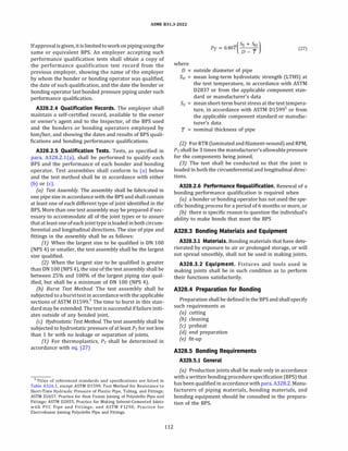
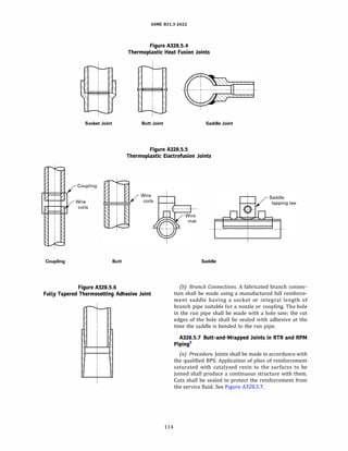
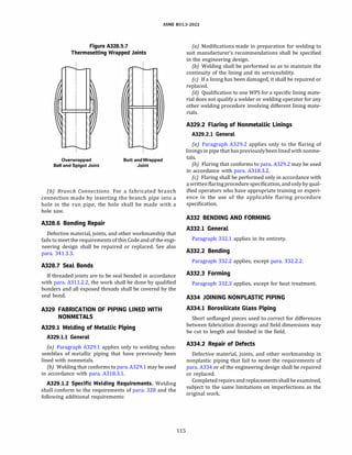
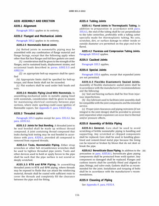
![ASME 831.3-2022
Table A341.3.2
Acceptance Criteria for Bonds
Thermoplastic Material RTR and RPM Materials
-----------�------------- [Note (1)] - Adhesive
Type of Imperfection Hot Gas Welded Joint Solvent Cemented Joint Heat Fusion Joint Cemented Joint
Cracks None permitted Not applicable None permitted None permitted
None permitted
None permitted
None permitted
None permitted
Adhesive, 25%
Unfilled areas in joint None permitted None permitted None permitted
Unbonded areas in joint
Inclusions of charred material
Unfused filler material inclusions
Protrusion of material into pipe
None permitted None permitted None permitted
None permitted Not applicable None permitted
None permitted Not applicable Not applicable
Not applicable Cement, 50% Fused material, 25%
bore, % of pipe wall thickness
NOTE: (1) RTR = reinforced thermosetting resin; RPM = reinforced plastic mortar.
PART 10
INSPECTION, EXAMINATION, AND TESTING
A340 INSPECTION
Paragraph 340 applies in its entirety.
A341 EXAMINATION
A341.l General
Paragraph 341.1 applies.
A341.2 Responsibility for Examination
Paragraph 341.2 applies in its entirety.
A341.3 Examination Requirements
A341.3.l Responsib ility for Examination.
Paragraph 341.3.1 applies, except for paras. 341.3.l(a)
and 341.3.l(b), which apply only for metals.
A341.3.2 Acceptance Criteria. Acceptance criteria
shall be as stated in the engineering design, and shall
at least meet the applicable requirements for bonds in
Table A341.3.2 and requirements elsewhere in the Code.
A341.3.3 Defective Components and Workmanship.
Paragraph 341.3.3 applies in its entirety.
A341.3.4 Progressive Sampling for Examination.
Paragraph 341.3.4 applies in its entirety.
A341.4 Extent of Required Examination
(22) A341.4.l Examination Normally Required. Piping in
Normal Fluid Service shall be examined to the extent
specified herein or to any greater extent specified in
the engineering design. Acceptance criteria are as
stated in para. A341.3.2 unless otherwise specified.
(a) Visual Examination. At least the following shall be
examined in accordance with para. 344.2:
(1) materials and components in accordance with
para. 341.4.l(a)(l).
117
(2) at least 5% of fabrication. For bonds, each type of
bond made by each bonder and bonding operator shall be
represented.
(3) 100% of fabricationfor bondsother than circum
ferential, except those in components made in accordance
with a listed specification.
(4) assembly and erection of piping in accordance
with paras. 341.4.l(a)(4), 341.4.l(a)(5), and
341.4.l(a)(6).
(b) Other Examination. At least 5% of all fused or
bonded joints within each designated lot shall be exam
ined by in-process examination in accordance with
para. 344.7. The joints to be examined shall include
the work of each bonder and bonding operator.
(c) Certifications and Records. Paragraph 341.4.l(c)
applies.
A341.4.2 Examination - Category D Fluid Service.
Piping and piping elements for Category D Fluid
Service as designated in the engineering design shall
be visually examined to the extent necessary to satisfy
the examiner that components, materials, and workman
ship conform to the requirements of this Code and the
engineering design.
A341.5 Supplementary Examination
A341.5.l General.Any applicable method of examina
tion described in para. 344 may be specified by the engi
neering design to supplement the examination required
bypara.A341.4. Theextentofsupplementaryexamination
to be performed and any acceptance criteria that differ
from those in para. A341.3.2 shall be specified in the engi
neering design.
A341.5.2 Examinations to Resolve Uncertainty.
Paragraph 341.5.3 applies.
A342 EXAMINATION PERSONNEL
Paragraph 342 applies in its entirety.](https://image.slidesharecdn.com/26162943-231229160810-282cb07a/85/ASME-B31-3-2022-Procces-piping-code-for-b31-3-144-320.jpg)
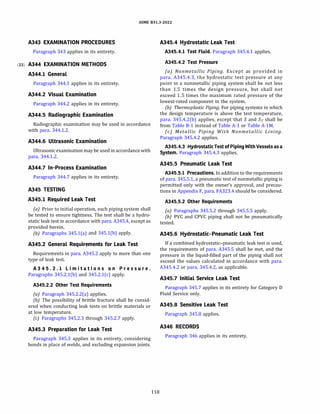
![ASME 831.3-2022
M305.2 Specific Requirements for Metallic Pipe
Pipe listed in para. 305.2.2 shall not be used. The provi
sion for severe cyclic conditions in para. 305.2.3 does not
apply [see para. M300(e)].
M306 METALLIC FITTINGS, BENDS, MITERS,
LAPS, AND BRANCH CONNECTIONS
General. Fittings, bends, miters, laps, and branch
connections may be used in accordance with
paras. M306.1 through M306.6. Pipe and other materials
used in such components shall be suitable for the manu
facturing process and the fluid service.
M306.l Pipe Fittings
Paragraph 306.1 applies in its entirety, with the excep
tion of paras. 306.1.3 and 306.1.4. See para. M306.1.3.
M306.l.3 Specific Fittings
(a) Proprietaryweldingbranch outlet fittings that have
been design proof tested successfully as prescribed in
ASME 816.9, MSS SP-97, or ASME BPVC, Section VIII, Divi
sion 1, UG-101 may be used within their established
ratings.
{b) Fittings conforming to MSS SP-43 and MSS SP-119
shall not be used.
(c) Proprietary "Type C" lap-joint stub-end butt
welding fittings shall not be used.
M306.2 Pipe Bends
Paragraph 306.2 applies, except that bends designed as
creased or corrugated shall not be used.
M306.3 Miter Bends
Amiterbend shallconformtopara.306.3.1 and shallnot
make a change in direction at a single joint (angle a in
Figure 304.2.3) greater than 22.5 deg. Paragraph
306.3.3 does not apply [see para. M300(e)].
M306.4 Fabricated or Flared Laps
M306.4.l General. The following requirements do not
apply to fittings conforming to para. M306.1, nor to laps
integrally forged on pipe ends. Paragraph 306.4.1 applies.
M306.4.2 Flared Laps. Flared laps shall not be used.
M306.5 Fabricated Branch Connections
The following requirements do not apply to fittings
conforming to para. M306.1. Paragraph 306.5.1 applies,
with the following exceptions:
(a) Of the methods listed in para. 304.3.l(a), the one in
para. 304.3.l(a)(3) may be used only if those in paras.
304.3.l(a)(l) and 304.3.l(a)(2) are unavailable.
120
(b) Of the branch connections described in
paras. 304.3.2(b) and 304.3.2(c), those having threaded
outlets are permitted only in accordance with para.
M314 and those having socket welding outlets are
permitted only in accordance with para. M311.2.
M306.6 Closures
The following requirements do not apply to blind
flanges or to fittings conforming to para. M306.1. Of
the closures described in para. 304.4, flat closures in
accordance with ASME BPVC, Section VIII, Division 1,
UG-34and UW-13, and conical closures without transition
knuckles [UG-32(g) and UG-33(f)], may be used only if
others are not available. The requirements in M306.5
apply to openings in closures [see also para. 304.4.2(b)].
M307 METALLIC VALVES AND SPECIALTY
COMPONENTS
The following requirements for valves shall also be met
as applicableby otherpressure-containingpipingcompo
nents, e.g., traps, strainers, and separators. See also
Appendix F, paras. F301.4 and F307.
M307.l General
Paragraph 307.1 applies, subject to the requirements in
para. M307.2.
M307.2 Specific Requirements (22)
(a) Paragraphs 307.2.2 and 307.2.3 apply.
{b) Valves having threaded bonnet joints (other than
union joints) shall not be used.
(c) Only metallic valves conforming to the following
requirements may be used:
(1) Special consideration shall be given to valve
design to prevent stem leakage to the environment.
(2) Bonnet or cover plate closures and body joints
shall be flanged, secured by at least four bolts with
gasketing conforming to para. 308.4; or proprietary,
attached by bolts, lugs, or other substantial means, and
having a gasketdesign that increases gasket compression
as fluid pressure increases; or secured with a full pene
tration weld made in accordance with para. M311; or
secured by a straight thread sufficient for mechanical
strength, a metal-to-metal seat, and a seal weld made
in accordance with para. M311, all acting in series.
M308 FLANGES, BLANKS, FLANGE FACINGS, AND
GASKETS
Paragraph 308.1 applies in its entirety.
M308.2 Specific Requirements for Metallic
Flanges
Paragraph 308.2.4 does not apply [see para. M300(e)].
The following shall not be used:](https://image.slidesharecdn.com/26162943-231229160810-282cb07a/85/ASME-B31-3-2022-Procces-piping-code-for-b31-3-147-320.jpg)
![ASME 831.3-2022
(a) single-welded slip-on flanges
(b) expanded-joint flanges
(c) slip-on flanges used as lapped flanges unless the
requirements in para. 308.2.l(c) are met
(d) threaded metallic flanges, except those employing
lens rings or similar gaskets and those used in lined pipe
where the liner extends over the gasket face
M308.3 Flange Facings
Paragraph 308.3 applies in its entirety.
M308.4 Gaskets
Paragraph 308.4 applies in its entirety.
M308.5 Blanks
All blanks shall be marked with material, rating, and
size.
M309 BOLTING
Paragraph 309 applies, except for para. 309.2.4 [see
para. M300(e)].
PART 4
FLUID SERVICE REQUIREMENTS FOR METALLIC
PIPING JOINTS
M310 METALLIC PIPING, GENERAL
Paragraph 310 applies in its entirety.
M311 WELDED JOINTS IN METALLIC PIPING
Welded joints may be made in any metal for which it is
possible to qualify welding procedures, welders, and
welding operators in accordance with para. M328.
M311.1 General
Paragraph 311.1 applies with the following exceptions:
(a) Split backing rings shall not be used.
{b) Socket weldedjoints greater than ON 50 (NPS2)are
not permitted.
(c) Examination shall be in accordance with
para. M341.4.
M311.2 Specific Requirements
Paragraphs 311.2.l(a); 311.2.2(a), 311.2.2(b), and
311.2.2(d); 311.2.3; and 311.2.4 apply.
M312 FLANGED JOINTS IN METALLIC PIPING
Paragraph 312 applies in its entirety.
121
M313 EXPANDED JOINTS IN METALLIC PIPING
Expanded joints shall not be used.
M314 THREADED JOINTS IN METALLIC PIPING
M314.1 General
Paragraphs 314.l(a), 314.l(b), and 314.l(c) apply.
M314.2 Specific Requirements
M314.2.l Taper-Threaded Joints. Paragraph 314.2.1
applies except that only components suitable for
Normal Fluid Service in sizes 8 :5 ON :5 25 (% :5 NPS :5
1) are permitted (see Table 314.2.1). Sizes smaller
than ON 20 (NPS %) shall be safeguarded (see
Appendix G).
M314.2.2 Straight-Threaded Joints. Paragraph (22)
314.2.2 applies. In addition, components shall have
adequate mechanical strength and the joint shall have
a confined seating surface not subject to relative rotation
as or after the joint is tightened. [See Figure 335.3.3, illus
trations (b) and (c) for acceptable designs.]
M315 TUBING JOINTS IN METALLIC PIPING
Paragraph 315 applies, except for para. 315.2(b).
M316 CAULKED JOINTS
Caulked joints shall not be used.
M317 SOLDERED AND BRAZED JOINTS
Soldered, brazed, and braze welded joints shall not be
used.
M318 SPECIAL JOINTS IN METALLIC PIPING
Paragraph 318applies, withtheexceptionthat adhesive
joints and bell type joints shall not be used.
PART 5
FLEXIBILITY AND SUPPORT OF METALLIC PIPING
M319 FLEXIBILITY OF METALLIC PIPING
Paragraph 319 applies, with the exception that the
simplified rules in para. 319.4.l(c) do not apply.
M320 ANALYSIS OF SUSTAINED LOADS
Paragraph 320 applies.
M321 PIPING SUPPORT
Paragraph 321applies, exceptthatsupportingelements
welded to the piping shall be of listed material.](https://image.slidesharecdn.com/26162943-231229160810-282cb07a/85/ASME-B31-3-2022-Procces-piping-code-for-b31-3-148-320.jpg)


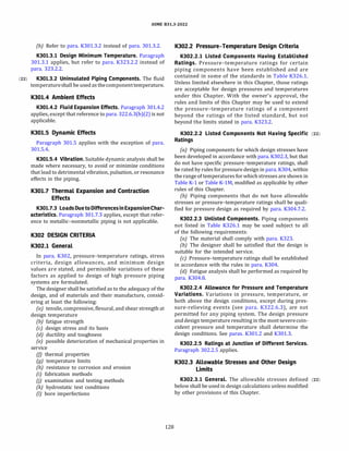
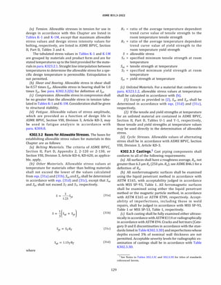
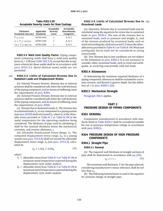
![(22)
ASME 831.3-2022
C C; + C0
the sum of mechanical allowances2
(thread or
groove depth) plus corrosion and erosion allow
ances (where c; = the sum of internal allowances
and c0 = the sum of external allowances). For
threaded components, the nominal thread
depth (dimension h of ASME 81.20.1 or equiva
lent) shall apply, except that for straight threaded
connections, the external thread groove depth
need not be considered provided
(1) it does not exceed 20% of the wall thick-
ness
(2) the ratio of outside to inside diameter,
D/d, is greater than 1.1
(3) the internally threaded attachment
provides adequate reinforcement
(4J the thread plus the undercut area, if any,
does not extend beyond the reinforcement for a
distance more than the nominal wall thickness of
the pipe
t = pressure design wall thickness, as calculated in
para. K304.1.2 for internal pressure, or in accor
dance with the procedure listed in para. K304.1.3
for external pressure
tm minimum required wall thickness, including
mechanical, corrosion, and erosion allowances
Adequate reinforcement by the attachment is defined as
that necessary to ensure that the static burst pressure of
the connection will equal or exceed that of the unthreaded
portion of the pipe. The adequacy of the reinforcement
shall be substantiated as required by para. K304.7.2.
K304.l.2 Straight Pipe Under Internal Pressure. The
internal pressure design wall thickness, t, shall be not less
than that calculated in accordance with eq. (34a) for pipe
with a specified outside diameter and minimum wall
thickness, or eq. (34b) for pipe with a specified inside
diameter and minimum wall thickness3
or
-
d + 2c;
[ (PIS) ]
t----e -1
2
(34a)
(34b)
Alternatively, the internal design gage pressure, P, may
be calculated by eq. (3Sa) or eq. (3Sb)3
P=Sxln °
�
D - 2c
�
D -2(T - c;)
(35a)
2 For machined surfaces or grooves where the tolerance is not speci
fied, the tolerance shall be assumed to be 0.5 mm (0.02 in.) in addition to
the specified depth of the cut.
131
or
p = S X 1)_d_+_2_(T_-_,'-
o) l
l d + 2c; J (35b)
where
D = outsidediameterofpipe. Fordesigncalculations in
accordance with this Chapter, the outside
diameter of the pipe is the maximum value allow
able under the specifications.
d inside diameter of pipe. For design calculations in
accordance with this Chapter, the inside diameter
of the pipe is the maximum value allowable under
the specifications.
P = internal design gage pressure
S = allowable stress from Table K-1 or Table K-lM
T = pipe wall thickness (measured or minimum in
accordance with the purchase specification)
K304.l.3 Straight Pipe Under External Pressure. The
pressure design thickness for straight pipe under external
pressure shall be determined in accordance with
para. K304.1.2. Straight pipe under external pressure
shall also meet the criteria against buckling given in
ASME BPVC, SectionVIII, Division 3, Article KD-2, KD-222.
K304.2 Curved and Mitered Segments of Pipe
K304.2.l Pipe Bends. The minimum required wall
thickness, tm, of abend, after bending, may be determined
as for straight pipe in accordance with para. K304.1,
provided that the bend radius of the pipe centerline is
equal to or greater than ten times the nominal pipe
outside diameter and the tolerances and strain limits
ofpara. K332 are met. Otherwise the designshall be qual
ified as required by para. K304.7.2.
K304.2.2 Elbows. Manufactured elbows not in accor
dance with para. K303 and pipe bends not in accordance
with para. K304.2.1 shall be qualified as required by para.
K304.7.2.
K304.2.3 Miter Bends. Miter bends are not permitted.
K304.2.4 Curved Segments of Pipe Under External
Pressure. The wall thickness of curved segments of
pipe subjected to external pressure may be determined
as specified for straight pipe in para. K304.1.3.
K304.3 Branch Connections
K304.3.l General. Acceptable branch connections
include a fitting in accordance with para. K303, an
extruded outlet in accordance with para. 304.3.4, or a
3 Any mechanical, corrosion, or erosion allowance, c, not specified as
internal, C;, or external, c0, shall be assumed to be internal, i.e., c = C; and c0
= 0.](https://image.slidesharecdn.com/26162943-231229160810-282cb07a/85/ASME-B31-3-2022-Procces-piping-code-for-b31-3-158-320.jpg)
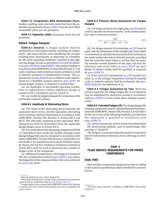
![ASME 831.3-2022
Table K305.1.2
Required Ultrasonic or Eddy Current Examinationof Pipe
and Tubing for Longitudinal Defects
Diameter, mm (in.)
d < 3.2 (%)
or D < 6.4 (%)
3.2 (%) 5 d 5 17.5 (11
/16)
and 6.4 (%) 5 D 5 25.4 (1)
d > 17.5 (1
1116)
or D > 25.4 (1)
Examination
Required
None
Eddy current (ET)
[Note (1)] or
ultrasonic (UT)
Ultrasonic (UT)
Paragraph
Reference
K344.8 or
K344.6
K344.6
NOTE: (1) This examination is limited to cold drawn austenitic stain
less steel pipe and tubing.
KJOS.I Requirements
K305.1.1 General. Pipeandtubingshallbeeitherseam
less or longitudinally welded with straight seam and a
joint quality factor E1
= 1.00, examined in accordance
with Note (2) of Table K341.3.2. Spiral (helical seam)
welds are not permitted.
K305.1.2 Additional Examination. Pipe and tubing
shall have passed a 100% examination for longitudinal
defects in accordance with Table K305.1.2. This examina
tion is in addition to acceptance tests required by the
material specification.
K305.1.3 Heat Treatment. Heat treatment, if required,
shall be in accordance with para. K331.
K305.1.4 Unlisted Pipe andTubing. Unlisted pipe and
tubing may be used only in accordance with
para. K302.2.3.
K306 FITTINGS, BENDS, AND BRANCH
CONNECTIONS
Pipe and other materials used in fittings, bends, and
branch connections shall be suitable for the manufac
turing or fabrication process and otherwise suitable
for the service.
K306.l Pipe Fittings
K306.l.1 General. All castings shall have examination
and acceptance criteria in accordance with para. K302.3.3.
All welds shall have a weld quality factor E1 = 1.00, with
examination and acceptance criteria in accordance with
paras. K341 through K344. Spiral(helical seam) welds are
not permitted. Listed fittings may be used in accordance
with para. K303. Unlisted fittings may be used only in
accordance with para. K302.2.3.
K306.1.2 Specific Fittings
(a) Socket welding fittings are not permitted.
134
(b) Threaded fittings are permitted only in accordance
with para. K314.
(c) Branch connection fittings (see para. 300.2) whose
design has been performance tested successfully as
required by para. K304.7.2(b) may be used within
their established ratings.
K306.2 Pipe Bends
K306.2.1 General. A bend made in accordance with
para. K332.2 and verified for pressure design in accor
dance with para. K304.2.1 shall be suitable for the
same service as the pipe from which it is made.
K306.2.2 Corrugated and Other Bends. Bends of other
design (such as creased or corrugated) are not permitted.
K306.3 Miter Bends
Miter bends are not permitted.
K306.4 Fabricated or Flared Laps
Only forged laps are permitted.
K306.5 Fabricated Branch Connections
Fabricated branch connectionsconstructed by welding
shall be fabricated in accordance with para. K328.5.4 and
examined in accordance with para. K341.4.
K307 VALVES AND SPECIALTY COMPONENTS
The followingrequirementsforvalvesshallalso be met,
asapplicable, by otherpressure-containingpiping compo
nents, e.g., traps, strainers, and separators. See also
Appendix F, paras. F301.4 and F307.
K307.l General
K307.1.1 ListedValves.Alistedvalve issuitableforuse
in High Pressure Fluid Service, except as stated in
para. K307.2.
K307.1.2 UnlistedValves. Unlisted valves may be used
only in accordance with para. K302.2.3.
K307.2 Specific Requirements
K307.2.1 Bonnet Bolting. The bonnets of bolted
bonnet valves shall be secured to their bodies by at
least four bolts.
K307.2.2 Stem Retention. Paragraph 307.2.2 applies.
K307.2.3 Double Seated Valves. Paragraph 307.2.3 (22)
applies, except for para. 307.2.3(b). Valve cavity design
shall be substantiated by one or more of the means
stated in paras. K304.7.2(b) and K304.7.2(c) for the
increased pressure-temperature condition.](https://image.slidesharecdn.com/26162943-231229160810-282cb07a/85/ASME-B31-3-2022-Procces-piping-code-for-b31-3-161-320.jpg)
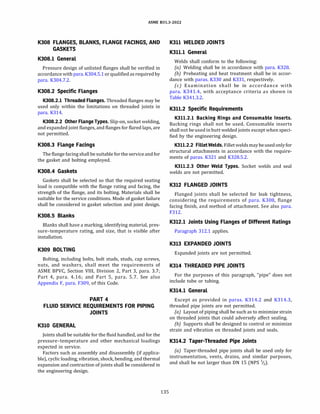
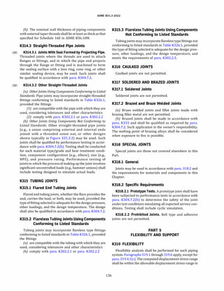
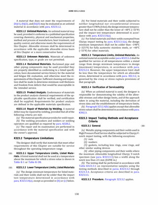
![ASME 831.3-2022
Table K323.3.l
Impact Testing Requirements
Column A
Test Pipe, Tubes, and Components Column B Column C
Characteristics Made From Pipe or Tubes Other Components, Fittings, Etc. Bolts
Tests on Number of tests As required by the material specification, or one test set per lot (Note (1)], whichever is greater, except as
Materials permitted by para. K323.3.l(a).
Location and (a) Transverse to the longitudinal (a) Transverse to the direction (a) Bolts :552 mm (:52 in.) nominal
orientation of axis, with notch parallel to of maximum elongation during size made in accordance with
specimens axis. [Note (4)] rolling or to direction of ASTM A320 shall meet the
(Note (3)] (b) Where component size, shape, major working during forging. impact requirements of that
or both do not permit Notch shall be oriented parallel specification.
specimens as specified in (a) to direction of maximum (b) For all other bolts, longitudinal
above, paras. K323.3.3(b) elongation or major working. specimens shall be taken. The
through K323.3.3(d) apply as (Note (4)] impact values obtained shall
needed. (b) If there is no single identifiable meet the transverse values of
axis, e.g., for castings or Table K323.3.5.
triaxial forgings, specimens
shall either meet the
longitudinal values of Table
K323.3.5, or three sets of
orthogonal specimens shall be
prepared, and the lowest
impact values obtained from
any set shall meet the
transverse values of
Table K323.3.5.
(c) Where component size,
shape, or both do not permit
specimens as specified in (a)
or (b) above, paras. K323.3.3(c)
and K323.3.3(d) apply as
needed.
Tests on Procedure Impact tests shall be valid only if the thickness of the test material meets the requirements of ASME BPVC,
Welds in qualification Section IX, Table QW-451.1 (including Notes), except that if the thickness is less than 16 mm (% in.), the
Fabrication thickness thickness of the test material shall be the minimum thickness qualified.
or Assembly limits
[Note (5)) Testing Impacttests shall be performed on theweld metal andthe HAZ ofthe procedure qualificationtest coupon at a
requirements test temperature no warmer than that determined in accordance with para. K323.3.4.
[Note (6)]
Location and (1) Weld metal impact specimens shall be taken across the weld with the notch in the weld metal. Each
orientation specimen shall be oriented so that the notch axis is normal to the surface of the material and one face of the
of specimens specimen shall be within 1.5 mm (1116 in.) of the surface of the material.
(2) Heat-affected zone impact specimens shall be taken across the weld and have sufficient length to locate
the notch in the heat-affected zone, after etching. The notch shall be cut approximately normal to the
material surface in such a manner as to include as much heat-affected zone material as possible in the
resulting fracture.
Acceptance (1) Impact tests shall meet the acceptance criteria applicable to the base metal in accordance with
criteria para. K323.3.5.
(2) Theimpactvalues obtained fromboththeweldmetal and HAZ specimens shallmeetthetransversevalues
in Table K323.3.5.
NOTES:
(1) A lot shall consist of pipe or components of the same nominal size, made from the same heat of material, and heat treated together. If a
continuous type furnace is used, pipe or components may be considered to have been heat treated together if they are processed during a
single continuous time period at the same furnace conditions.
(2) DELETED.
(3) Impact tests shall be performed on a representative sample of material after completion of all heat treatment and forming operations
involving plastic deformation, except that cold bends made in accordance with para. K304.2.1 need not be tested after bending.
(4) For welded piping components, specimens shall be taken from the base metal, weld metal, and the heat-affected zone.
(5) For welds in the fabrication or assembly of piping or components, including repair welds.
(6) The test piece shall be large enough to permit preparing the number of specimens required by para. K323.3. If this is not possible, additional
test pieces shall be prepared.
139
(22)](https://image.slidesharecdn.com/26162943-231229160810-282cb07a/85/ASME-B31-3-2022-Procces-piping-code-for-b31-3-166-320.jpg)
![ASME 831.3-2022
Figure K323.3.3
Example of an Acceptable Impact Test Specimen
I
I
Note(1)
GENERAL NOTE: This Figure illustrates how an acceptable trans
verse Charpy specimen can be obtained from a tubing or component
shape toosmall for a full length standard specimenin accordance with
ASTM A370. The corners of a longitudinal specimen parallel to and on
the side opposite the notch may be as shown.
NOTE: (1) Corners of the Charpy specimen [see para. K323.3.3(d)]
may follow the contour of the component within the dimension limits
shown.
(22) K323.3.3 Test Specimens
(a) Each set of impact test specimens shall consist of
three specimen bars. Impact tests shall be made using
standard 10 mm (0.394 in.) square cross section
Charpy V-notch specimen bars oriented in the transverse
direction.
{b) Where component size, shape, or both do not
permit specimens as specified in (a) above, standard
10 mm square cross-section longitudinal Charpy speci
mens may be prepared.
(c) Wherecomponentsize, shape, orbothdonotpermit
specimens as specified in (a) or (b) above, subsize longi
tudinal Charpyspecimensmaybeprepared.Testtempera
ture shall be reduced in accordance with Table 323.3.4.
(d) Ifnecessaryin(a), (b), or(c) above, cornersofspeci
mens parallel toand on the side oppositethe notch may be
as shown in Figure K323.3.3.
(22) K323.3.4 Test Temperatures. For all Charpy impact
tests, the test temperature criteria in (a) or (c) below
shall be observed.
(a) Charpy impact tests shall be conducted at a
temperature no warmer than the coldest of the following:
(1) 21°
C (70°
F)
(2) when the design minimum temperature is
warmerthanorequalto -48°
C(-55°
F), thelowestcompo
nent temperatureexpected in service at which a material
140
or weld will be subjected to a longitudinal or circumfer
ential stress greater than 41 MPa (6 ksi)
(3) when the design minimumtemperature is colder
than -48°
C (-55°
F), the design minimum temperature
(b) In specifying the temperatures in (a)(2) and (a)(3),
the following shall be considered:
(1) range of operating conditions
(2) upset conditions
(3) ambient temperature extremes
(4) required leak test temperature
(c) Where the largest possible test specimen has a
width along the notch less than the lesser of 80% of
the material thickness or 8 mm (0.315 in.), the test
shall be conducted at a reduced temperature in accor
dance with Table 323.3.4, considering the temperature
as reduced below the test temperature required by (a).
K323.3.5 Acceptance Criteria
(a) Minimum Energy Requirementsfor Materials Other
Than Bolting. The applicable minimum impact energy re
quirements for materials shall be those shown in
Table K323.3.5. Lateral expansion shall be measured in
accordance with ASTM A370 (for title see para.
323.3.2). The results shall be included in the impact
test report.
{b) Minimum Energy Requirements for Bolting Mate
rials. The applicable minimum energy requirements
shall be those shown inTable K323.3.5except as provided
in Table K323.3.l.
(c) Weld Impact Test Requirements. Where two base
metals having different required impact energy values
are joined by welding, the impact test energy require
ments shall equal or exceed the requirements of the
base material having the lower required impact energy.
(d) Retests
(1) Retest for Absorbed Energy Criteria. When the
average value of the three specimens equals or
exceeds the minimum value permitted for a single
specimen, and the value for more than one specimen is
below the required average value, or when the value
for one specimen is below the minimum value permitted
for a single specimen, a retest of three additional speci
mens shall be made. The value for each of these retest
specimens shall equal or exceed the required average
value.
(2) Retest for Erratic Test Results. When an erratic
result is caused by a defective specimen or uncertainty
in the test, a retest will be allowed. The report giving
test results shall specifically state why the original
specimen was considered defective or which step of
the test procedure was carried out incorrectly.](https://image.slidesharecdn.com/26162943-231229160810-282cb07a/85/ASME-B31-3-2022-Procces-piping-code-for-b31-3-167-320.jpg)
![ASME 831.3-2022
Table 1<323.3.5
Minimum Required Charpy V-Notch Impact Values
Energy, J (ft-lbt), for Specified Minimum Yield Strength,
Specimen Pipe Wall or Component Number of Specimens MPa (ksi) [Note (2)]
Orientation Thickness, mm (in.) [Note (1)] S932 (S135) >932 (>135)
Transverse s25 (sl) Average for 3 27 (20) 34 (25)
Minimum for 1 20 (15) 27 (20)
>25 and sSl (>l and s2) Average for 3 34 (25) 41 (30)
Minimum for 1 27 (20) 33 (24)
>51 (>2) Average for 3 41 (30) 47 (35)
Minimum for 1 33 (24) 38 (28)
Longitudinal s25 (sl) Average for 3 54 (40) 68 (SO)
Minimum for 1 41 (30) 54 (40)
>25 and sSl (>l and s2) Average for 3 68 (50) 81 (60)
Minimum for 1 54 (40) 65 (48)
>51 (>2) Average for 3 81 (60) 95 (70)
Minimum for 1 65 (48) 76 (56)
NOTES:
(1) See para. K323.3.S(c) for permissible retests.
(2) Energy values in this Table are for standard size specimens. For subsize specimens, these values shall bemultipliedby the ratio of the actual
specimen width to that of a full-size specimen, 10 mm (0.394 in.).
K323.4 Requirements for Materials
K323.4.l General. Requirementsin para. K323.4 apply
to pressure-containing parts, not to materials used as
supports, gaskets, packing, or bolting. See also
Appendix F, para. F323.4.
K323.4.2 Specific Requirements
(a) Ductile iron and other cast irons are not permitted.
(b) Zinc-coated materials are not permitted for pres-
sure containing components and may not be attached
to pressure-containing components by welding.
K323.4.3 Metallic Clad and Lined Materials.Materials
with metallic cladding or lining may be used in accordance
with the following provisions:
(a) For metallic clad or lined piping components, the
base metal shall be an acceptable material as defined in
para. K323, and the thickness used in pressure design in
accordance withpara. K304 shallnotincludethethickness
ofthe cladding or lining. The allowable stress used shall be
that forthe base metal atthe design temperature. For such
components, the cladding or lining may be any material
that, in the judgment of the user, is suitable for the
intended service and for the method of manufacture
and assembly of the piping component.
141
(b) Fabrication by welding of clad or lined piping
components andtheinspection andtestingofsuchcompo
nents shall be done in accordance with applicable provi
sions of ASME BPVC, Section VIII, Division 1, UCL-30
through UCL-52, and the provisions of this Chapter.
(c) Ifa metallic liner also serves as a gasket or as part of
the flange facing, the requirements and limitations in
para. K308.4 apply.
K323.5 Deterioration of Materials in Service
Paragraph 323.5 applies.
K325 MISCELLANEOUS MATERIALS
Paragraph 325 applies.
PART 8
STANDARDS FOR PIPING COMPONENTS
K326 REQUIREMENTS FOR COMPONENTS
K326.l Dimensional Requirements
K326.l.l Listed Piping Components. Dimensional
standards for piping components are listed in
Table K326.1. Dimensional requirements contained in](https://image.slidesharecdn.com/26162943-231229160810-282cb07a/85/ASME-B31-3-2022-Procces-piping-code-for-b31-3-168-320.jpg)
![(22)
ASME 831.3-2022
Table K326.1
Component Standards
Standard or Specification
Bolting
Square, Hex, Heavy Hex, and Askew Head Bolts and Hex, Heavy Hex, Hex Flange, Lobed Head, and Lag Screws (Inch
Series) ........................................................................................
Nuts for General Applications: Machine Screw Nuts, Hex, Square, Hex Flange, and Coupling Nuts (Inch Series)
Metallic Fittings, Valves, and Flanges
Pipe Flanges and Flanged Fittings: NPS 1h Through NPS 2 4 Metric/Inch Standard [Note (1)] ....................
Factory-Made Wrought Buttwelding Fittings [Note (1)] ...................................................
Forged Fittings, Socket-Welding and Threaded [Note (1)] .................................................
Valves - Flanged, Threaded, and Welding End [Note (1)] .................................................
Line Blanks [Note (1)] ......................................., ., ., ........, · , · · · · · · · · · · , · , · · · · · · · · ·
Standard Marking System for Valves, Fittings, Flanges, and Unions ..........................................
High-Pressure Chemical Industry Flanges and Threaded Stubs for Use with Lens Gaskets (Note (1)] ...............
Metallic Pipe and Tubes (Note (2))
Welded and Seamless Wrought Steel Pipe (Note (1)] .....................................................
Stainless Steel Pipe (Note (1)] .......................................................................
Miscellaneous
Threading, Gauging, and Inspection of Casing, Tubing, and Line Pipe Threads .................................
Unified Inch Screw Threads (UN and UNR Thread Form) .................................................
Pipe Threads, General Purpose (Inch) .................................................................
Metallic Gaskets for Pipe Flanges .....................................................................
Buttwelding Ends .................................................................................
Surface Texture (
Surface Roughness, Waviness, and Lay) ..................................................
Designation
ASME 818.2.1
ASME 818.2.2
ASME 816.
5
ASME 816.9
ASME 816.1 1
ASME 816.
34
ASME 816.48
MSS SP- 25
MSS SP-65
ASME 8
3
6.lOM
ASME B3
6.l 9M
AP I SB
ASME 81.1
ASME 81.20.1
ASME 816.20
ASME 816.25
ASME 846.1
GENERAL NOTE: The approved edition dates of these standards and specifications, along with the names and addresses of the sponsoring
organizations, are shown in Appendix E.
NOTES:
(1) The use of components made in accordance with these standards is permissible, provided they are
(a) examined and leak tested in accordance with the requirements of paras . K34 1 and K345, respectively .
(b) impact tested inaccordance with the methods describedin paras . K323.3.l through K323.3.4,and meet the acceptance criteria specified in
para . K323.3.5.Note that such impact testing may require the destruction of one component from the same lot as the component to be used in
service [see Table K323.3.l, Note (1)].
(c) in accordance with the fluid service requirements in Parts 3and 4 of this Chapter .
(2) See also Appendix K.
specificationslistedinAppendixKshallalso beconsidered
requirements of this Code.
K326.1.2 Unlisted Piping Components. Piping compo
nents not listed in Table K326.1 or Appendix K shall meet
the pressure design requirements described in para.
K302.2.3 and the mechanical strength requirements
described in para. K302.5.
K326.1.3 Threads. The dimensions of piping connec
tionthreadsnototherwisecoveredbyagoverningcompo
nent standard or specification shall conform to the
requirements of applicable standards listed in
Table K326.1 or Appendix K.
142
K326.2 Ratings of Components
K326.2.1 Listed Components. The pressure-tempera
ture ratings of components listed in Table K326.1 are
accepted for pressure design in accordance with para.
K303.
K326.2.2 Unlisted Components. The pressure
temperature ratings of unlisted piping components
shall conform to the applicable provisions of para. K304.
K326.3 Reference Documents
The documents listed in Table K326.1 contain refer
ences to codes, standards, and specifications not listed
inTable K326.1. Suchunlistedcodes, standards, andspeci
fications shall be used only in the context of the listed
documents in which they appear.](https://image.slidesharecdn.com/26162943-231229160810-282cb07a/85/ASME-B31-3-2022-Procces-piping-code-for-b31-3-169-320.jpg)
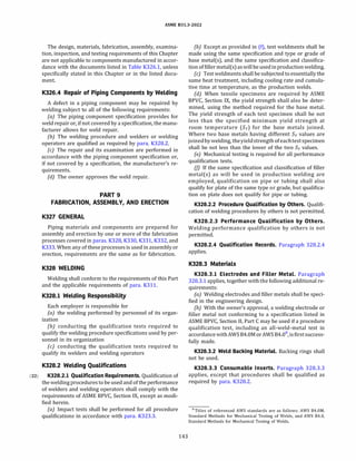
![ASME 831.3-2022
K328.4 Preparation for Welding
K328.4.l Cleaning. Paragraph 328.4.1 applies.
K328.4.2 End Preparation
(a) General
(1) Butt weld end preparation is acceptable only if
the surface is machined or ground to bright metal.
(2) Butt welding endpreparationcontained in ASME
816.25 orany other endpreparationthat meets theproce
dure qualification is acceptable. [For convenience, the
basic bevel angles taken from ASME 816.25, with some
additional J-bevel angles, are shown in Figure 328.4.2,
illustrations (a) and (b).]
{b) Circumferential Welds
(1) If components' ends are trimmed as shown in
Figure 328.4.2, illustration (a) or (b) to accommodate
consumable inserts, or as shown in Figure K328.4.3 to
correct internal misalignment, such trimming shall not
result in a finished wall thickness before welding less
than the required minimum wall thickness, tm,
(2) It is permissible to size pipe ends of the same
nominal size to improve alignment, if wall thickness re
quirements are maintained.
(3) Where necessary, weld metal may be deposited
on the inside or outside of the component to permit align
ment or provide for machining to ensure satisfactory
seating of inserts.
(4) When a butt weld joins sections of unequal wall
thickness and the thicker wall is more than 11
/2 times the
thickness of the other, endpreparationandgeometryshall
be in accordance with acceptable designs for unequal wall
thickness in ASME 816.5.
(22) K328.4.3 Alignment
(a) Girth Butt Welds
(1) Inside diameters of components at the ends to be
joined shall be aligned within the dimensional limits in the
welding procedure and the engineering design, except
that no more than 1.5 mm (1116 in.) misalignment is
permitted as shown in Figure K328.4.3.
(2) If the external surfaces of the two components
are not aligned, the weld shall be tapered between the
two surfaces with a slope not steeper than 1:4.
{b) Longitudinal Buttjoints. Preparation for longitudi
nal butt welds (not made in accordance with a standard
listed in Table K-1, Table K-lM, or Table K326.l) shall
conform to the requirements of (a).
(c) Branch Connection Welds
(1) The dimension m in Figure K328.5.4 shall not
exceed ±1.5 mm (6 in.).
(2) The dimension g in Figure K328.5.4 shall be
specifiedin the engineeringdesignand the welding proce
dure.
144
K328.5 Welding Requirements
K 3 2 8 . 5 . l Ge neral. T h e r e q u i r e m e n t s o f
paras. 328.5.l(b), 328.5.l(d), 328.5.l(e), and 328.5.l(f)
apply in addition to the requirements specified below.
(a) All welds, including tack welds, repair welds, and
t h e a d d i t i o n o f w e l d m e t a l f o r a l i g n m e n t
[paras. K328.4.2(b)(3) and K328.4.3(c)(l)], shall be
made by qualified welders or welding operators, in accor
dance with a qualified procedure.
(b) Tackweldsattheroot ofthejointshallbe madewith
filler metal equivalent to that used for the root pass. Tack
welds shall be fused with the root pass weld, except that
those that have cracked shall be removed. Bridge tacks
(above the root) shall be removed.
K328.5.2 Fillet Welds. Fillet welds, where permitted
(see para. K311.2.2), shall be fused with and shall
merge smoothly into the component surfaces.
K328.5.3 Seal Welds. Seal welds are not permitted.
K328.5.4 Welded Branch Connec tions. Branch (22)
connectionfittings(seepara.300.2), attachedbysmoothly
contoured full penetration groove welds of a design that
permits 100% interpretable radiographic examination,
are the only types acceptable.
Figure K328.5.4 shows acceptable details of welded
branch connections. The illustrations are typical and
are not intended to exclude acceptable details not shown.
K328.5.5 Fabricated Laps. Fabricated laps are not
permitted.
K328.6 Weld Repair
Paragraph 328.6 applies, except that procedures and
performance shall be qualified as required by para.
K328.2.l. See also para. K341.3.3.
Figure K328.4.3
Pipe Bored for Alignment:
Trimming and Permitted Misalignment
Round corner
Permitted misalignment
� 1.5 mm (1
/rn in.). See WPS. ,,; 30 deg](https://image.slidesharecdn.com/26162943-231229160810-282cb07a/85/ASME-B31-3-2022-Procces-piping-code-for-b31-3-171-320.jpg)
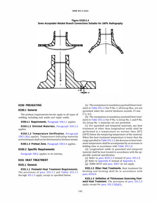
![ASME 831.3-2022
(b) conducting the qualification tests required to
qualify the brazing procedure specifications used by per
sonnel in its organization
(c) conducting the qualification tests required to
qualify its brazers and brazing operators
K333.2 Brazing Qualifications
K333.2.l Qualification Requirements. The qualifica
tionofbrazing procedures, brazers, and brazing operators
shall be in accordance with the requirements of ASME
BPVC, Section IX.
K333.2.2 Procedure Qualification by Others. Brazing
procedure specifications qualified by a technically compe
tent group or agency may be used, provided the following
requirements are met:
(a) The owner shall approve the use of brazing proce
dure specifications qualified by others.
(b) The brazing procedure specificationsshall meet the
requirements of para. K333.2.1.
(c) The employer's business name shall be shown on
each brazing procedure specification and on each brazing
procedure qualification record.
(d) The employer shall accept responsibility for each
brazing procedure qualification performed by others
by signing and dating each brazing procedure qualifica
tion record.
(e) The employer shall conduct the qualification tests
required to qualify its brazers and brazing operators.
K333.2.3 Performance Qualification by Others. An
employer may accept the performance qualification of
a brazer or brazing operator made by a technically compe
tent group or agency, provided the following require
ments are met:
(a) The owner shall approve the use of brazing perfor
mance qualifications qualified by others.
{b) The brazer or brazing operator performance quali
fications were made on pipe test coupons.
(c) The employer shall have a brazing procedure spec
ification such that the performance qualification is within
thelimitsoftheessential variablessetforthinASME BPVC,
Section IX.
(d) The employer shall have a copy of the performance
qualification test record. The record shall show the name
ofthe technically competent group or agency by whom the
brazer or brazing operator was qualified and the date of
that qualification. Evidence shall also be provided that the
brazer or brazing operator has maintainedqualification in
accordance with ASME BPVC, Section IX, QB-322.
(e) The employer's business name shall be shown on
the brazing performance qualification record.
(f] The employer shall accept responsibility for the
brazing performance qualifications performed by
others by signing and dating the qualification.
147
K333.2.4 Qualification Records. The employer shall
maintain copies of the brazing procedure specification
and performance qualification records specified by
ASME BPVC, Section IX. These records shall be made avail
able to the Inspector upon request.
K333.3 Materials
Brazing filler metals and flux shall beinaccordance with
para. 333.2.1.
K333.4 Preparation and Cleaning
Paragraph 333.3 applies, except that soldering is not
permitted.
K335 ASSEMBLV AND ERECTION (22)
Paragraphs 335.1 and 335.2 apply.
K335.3 Threaded Joints
Paragraph 335.3 applies, except that threaded joints
shall not be seal welded.
K335.4 Special Joints
Special joints (as defined in para. K318) shall be
installed and assembled in accordance with the manufac
turer's instructions, as modified by the engineering
design. Care shall be taken to ensure full engagement
of joint members.
K335.5 Cleaning of Piping
See Appendix F, para. F335.9.
PART 10
INSPECTION, EXAMINATION, AND TESTING
K340 INSPECTION
Paragraphs 340.1 through 340.4 apply.
K341 EXAMINATION
Paragraphs 341.1 and 341.2 apply.
K341.3 Examination Requirements
K341.3.l General. Prior to initial operation, each
piping installation, including components and workman
ship, shall be examined in accordance with para. K341.4
and the engineering design. If heat treatment is
performed, examination shall be conducted after its
completion.
K341.3.2 Acceptance Criteria. Acceptance criteria
shall be as stated in the engineering design and shall
at least meet the applicable requirements stated in (a)
and (b) below, and elsewhere in this Chapter.](https://image.slidesharecdn.com/26162943-231229160810-282cb07a/85/ASME-B31-3-2022-Procces-piping-code-for-b31-3-174-320.jpg)
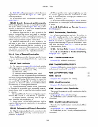
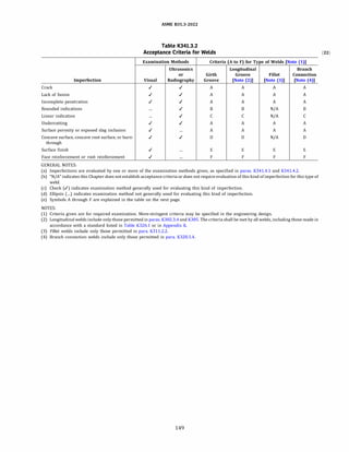
![(22)
Symbol
A
B
c
D
E
F
NOTES:
ASME 831.3-2022
Criterion Value Notes for Table K341.3.2
Criterion
Measure Acceptable Value Limits [Note (1))
Extent of imperfection Zero(no evident imperfection)
Size and distribution of rounded indications See ASME BPVC, Section VIII, Division 1, Appendix 4 (Note(2)
]
Linear indications. Linear indications are
unacceptable if the amplitude exceeds the
reference level, or linear indications have lengths
that exceed
Individual length (Note(3)
]
Cumulative length
6 mm(% in.) for T.v ::; 19mm(% in.)
fw/3 for 19 mm(% in.)
< Tw .'.', 57mm(2% in.)
19 mm(% in.) for fw > 57mm(2% in.)
::;f.v in any 12 fw weld length [Note(2)
]
Depth of surface concavity, root surface concavity, or fw, mm(in.) Depth, mm(in.)
burn-through
-<_-1-3�(<_-1
�,,
2
�)
��������1 -5 �( -1
�,)������������
Surface roughness
Height of face reinforcement or root reinforcement
(Note(4)
] in any plane through the weld shall
be within the limits of the applicable height
value in the tabulation at the right. Weld metal
shall be fused with and merge smoothly into
the component surfaces.
r $ · $ '16
>13(>1
/2) and ,;;51(,;;2) ,;;3(,;;%)
>51(>2) ,;;4($%2)
and total joint thickness including weld reinforcement ?.fw
,;;12.5 µm(,;;500 µin.) Ra(see ASME 846.1 for definition of roughness
average, Ra)
Tw, mm(in.)
,;;13($
1
/2)
>13(>1
/2) and ,;;51(,;;2)
>51(>2)
,;;1.5(,;;1Ji6)
,;;3(,;;%)
,;;4($%2)
Height, mm(in.)
(1) Where two limiting values are given, the lesser measured value governs acceptance. Tw is the nominal wall thickness of the thinner of two
components joined by a butt weld.
(2) Porosityand inclusions suchasslagor tungsten are defined as rounded indicationswhere themaximumlengthisthree timesthewidthorless.
These indications may be circular, elliptical, or irregular in shape; may have tails; and may vary in density. Indications where the length is
greater than three times the width are defined as linear indications and may also be slag, porosity, or tungsten.
(3) For ultrasonic examination, refer to para. K344.6.3 for acceptable value limits.
(4) For groove welds, height is the lesser of the measurements made from the surfaces of the adjacent components. For fillet welds, height is
measured from the theoretical throat; root reinforcement does not apply. Required thickness tm shall not include face reinforcement or root
reinforcement.
150](https://image.slidesharecdn.com/26162943-231229160810-282cb07a/85/ASME-B31-3-2022-Procces-piping-code-for-b31-3-177-320.jpg)
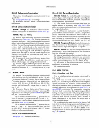
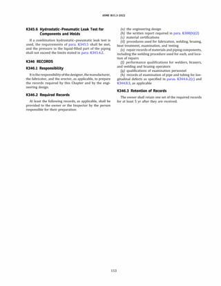
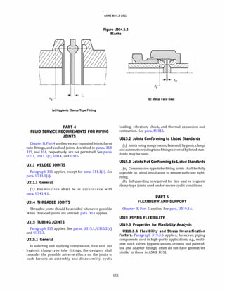
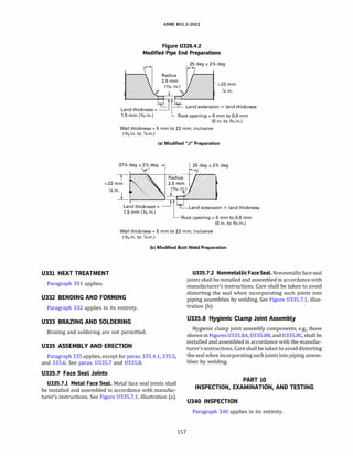
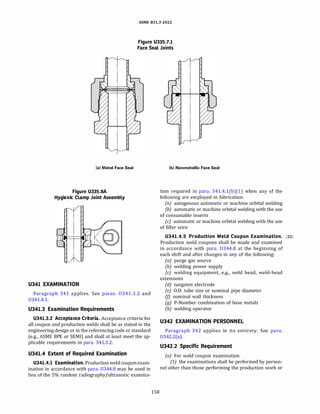
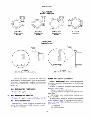
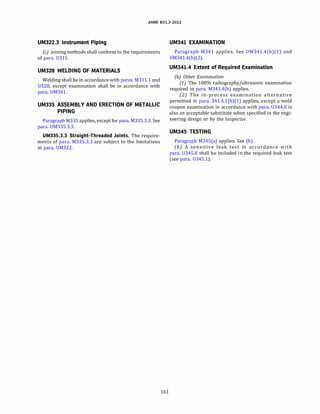
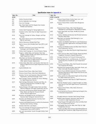
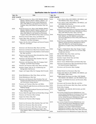
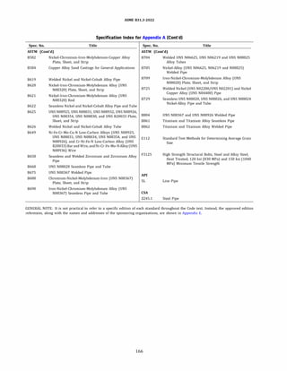
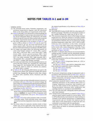
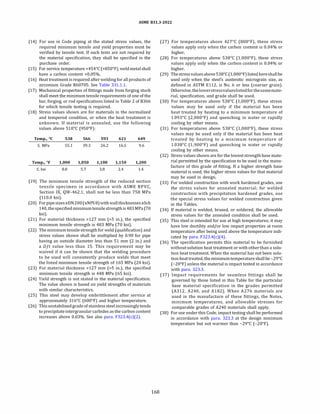
![ASME 831.3-2022
(39) This material when used below -29°
C (-20°
F) shall be
impact tested if the carbon content is above 0.10%.
(40) Stress values shown are 90% of those for the corre
sponding core material.
(41) The tension test specimen from plate 12.7 mm (1;2 in.) and
thicker is machined from the core and does not include the
cladding alloy; therefore, the stress values listed are those
for materials less than 12.7 mm.
(42) This material may be used only in nonpressure applica
tions.
(43) *The stress values given for this material are not applicable
when either welding or thermal cutting is employed [see
para. 323.4.2(c)].
(44) For stress relieved tempers (T351, T3510, T3511, T451,
T4510, T4511, T651, T6510, T6511), stress values for
material in the listed temper shall be used.
(45) Stress values shown are applicable for "die" forgings only.
(46) The minimum temperature shown is for the heaviest wall
meeting the specified mechanical property requirements
in the specification. The minimum temperature for lighter
walls shall be as shown in the following tabulation:
Impact Test Temperature (0
C) for Plate Thicknesses Shown
Spec. No. and Grade Max. 51 mm Over 51 mm to 76 mm
A203 A -68 -59
A203 B -68 -59
A203 D -101 -87
A203 E -101 -87
Impact Test Temperature (°
F) for Plate Thicknesses Shown
Spec. No. and Grade Max. 2 in. Over 2 in. to 3 in.
A203 A -90 -75
A203 B -90 -75
A203 D -150 -125
A203 E -150 -125
(47) If no welding is employed in fabrication of piping from
these materials, the stress values may be increased to
230 MPa (33.3 ksi).
(48) The stressvalue to be used for this gray ironmaterialat its
upper temperature limit of 232°
C (450°
F) is the same as
that shown in the 204°
C (400°
F) column.
(49) If the chemical composition of this Grade is such as to
render it hardenable, qualification under P-No. 6 is
required.
(50) This material is grouped in P-No. 7 because its harden
ability is low.
(51) This material may require special consideration for
welding qualification. See ASME BPVC, Section IX, Table
QW/QB-422. For use in this Code, a qualified WPS is
required for each strength level of material.
(52) These materials are normally microalloyed with Cb, V,
and/or Ti. Supplemental specifications agreed to by manu
facturer and purchaser commonly establish chemistry
more restrictive than the base specification, as well as
plate rolling specifications and requirements for weld
ability (i.e., C-equivalent) and toughness.
169
(53) Stress relief heat treatment is required for service above
232°
C (450°
F).
(54) The maximum operating temperature is arbitrarily set at
260°
C (500°
F) because hard temper adversely affects
design stress in the creep rupture temperature ranges.
(55) Pipe produced to this specification is not intended for high
temperature service. The stress values apply to any heat
treatment condition, delivery condition, and service condi
tion allowed for the applicable pipe strength level. Ther
momechanical rolled or thermomechanical formed pipe
shall not be heat treated at a temperature warmer than
580°
C (1,075°
F).
(56) Because of thermal instability, this material is not recom
mended for service above 427°
C (800°
F).
(57) Conversion of carbides to graphite may occur after
prolonged exposure to temperatures over 427°
C
(800°
F). See para. F323.4(b)(2).
(58) Conversion of carbides to graphite may occur after
prolonged exposure to temperatures over 468°
C
(875°
F). See para. F323.4(b)(3).
(59) For temperatures above 482°
C (900°
F), consider the
advantages of killed steel. See para. F323.4(b)(4).
(60) Alloy 625 (UNS N06625) in the annealed condition is
subject to severelossof impact strength atroomtempera
ture after exposure in the range of538°
Cto760°
C(1,000°
F
to 1,400°
F).
(61) Annealed at approximately 982°
C (1,800°
F).
(62) Annealed at approximately 1 121°
C (2,050°
F).
(63) The pipe grades listed below, marked as either or both
grades in accordance with API Specification SL, shall be
considered as equivalents and treated as listed materials.
API SL Grade Equivalents
X-Grade L-Grade
A25 L175
A L210
B L245
X42 L290
X46 L320
X52 L360
X56 L390
X60 L415
X65 L450
X70 L485
X80 L555
(64) For use under this Code, the heat treatment requirements
for pipe manufactured to A671, A672, and A691 shall be as
required by para. 331 for the particular material being
used.](https://image.slidesharecdn.com/26162943-231229160810-282cb07a/85/ASME-B31-3-2022-Procces-piping-code-for-b31-3-196-320.jpg)
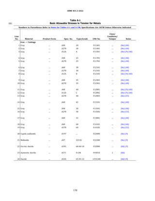
![ASME 831.3-2022
Table A-1
Basic Allowable Stresses in Tension for Metals
Numbers in Parentheses Refer to Notes for Tables A-1 and A-lM; Specifications Are ASTM Unless Otherwise Indicated
Min. Basic Allowable Stress, S, ksi, at Metal Temperature, 0
f [Notes (1), (2a)]
Min. Tensile Min. Yield Min.
Line Temp., 0
f Strength, Strength, Max. Temp. to
No. (6) ksi ksi Temp., 0
f 100 200 300 400 500 600 650
Iron - Castings
1 -20 20 400 2.0 2.0 2.0 2.0
2 -20 20 400 2.0 2.0 2.0 2.0
3 -20 21 400 2.0 2.0 2.0 2.0
4 -20 25 400 2.5 2.5 2.5 2.5
5 -20 25 400 2.5 2.5 2.5 2.5
6 -20 30 400 3.0 3.0 3.0 3.0
7 -20 30 400 3.0 3.0 3.0 3.0
8 -20 31 400 3.0 3.0 3.0 3.0
9 -20 35 400 3.5 3.5 3.5 3.5
10 -20 35 400 3.5 3.5 3.5 3.5
11 -20 40 400 4.0 4.0 4.0 4.0
12 -20 41 400 4.0 4.0 4.0 4.0
13 -20 40 650 4.0 4.0 4.0 4.0 4.0 4.0 4.0
14 -20 45 400 4.5 4.5 4.5 4.5
15 -20 50 400 5.0 5.0 5.0 5.0
16 -20 50 650 5.0 5.0 5.0 5.0 5.0 5.0 5.0
17 -20 55 400 5.5 5.5 5.5 5.5
18 -20 60 400 6.0 6.0 6.0 6.0
19 -20 60 650 6.0 6.0 6.0 6.0 6.0 6.0 6.0
20 -20 40 30 650 8.0 8.0 8.0 8.0 8.0 8.0 8.0
21 -20 50 32.5 650 10.0 10.0 10.0 10.0 10.0 10.0 10.0
22 -20 60 40 650 20.0 19.0 17.9 16.9 15.9 14.9 14.1
23 -20 65 30 100 20.0
24 -20 65 45 500 21.7 21.7 21.7 21.7 21.6
171](https://image.slidesharecdn.com/26162943-231229160810-282cb07a/85/ASME-B31-3-2022-Procces-piping-code-for-b31-3-198-320.jpg)
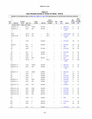
![ASME 831.3-2022
Table A-1
Basic Allowable Stresses in Tension for Metals (Cont'd)
Numbers in Parentheses Refer to Notes for Tables A-1 and A-lM; Specifications Are ASTM Unless Otherwise Indicated
Basic Allowable Stress, S, ksi, at Metal Temperature, 0
f [Notes (1), (2a)]
Min.Yield Max. Min.
Line Strength, Temp., Temp.
No. ksi Of to 100 200 300 400 500 600 650 700 750 800 850 900 950 1,000 1,050 1,100
Carbon Steel - Pipes and Tubes
1 24 900 15.0 14.7 14.2 13.7 13.0 12.3 11.9 11.5 10.7 9.2 7.9 5.9
2 24 1,100 15.0 14.7 14.2 13.7 13.0 12.3 11.9 11.5 10.7 9.2 7.9 5.9 4.0 2.5 1.6 1.0
3 25.4 400 15.0 15.0 14.7 14.2
4 25.4 400 15.0 15.0 14.7 14.2
5 26 1,100 15.7 15.7 15.3 14.8 14.1 13.3 12.8 12.4 10.7 9.2 7.9 5.9 4.0 2.5 1.6 1.0
6 30 400 16.0 16.0 16.0 16.0
7 30 300 16.0 16.0 16.0
8 30 850 16.0 16.0 16.0 16.0 16.0 15.3 14.6 12.5 10.7 9.2 7.9
9 30 1,100 16.0 16.0 16.0 16.0 16.0 15.3 14.6 12.5 10.7 9.2 7.9 5.9 4.0 2.5 1.6 1.0
10 30 1,100 16.0 16.0 16.0 16.0 16.0 15.3 14.6 12.5 10.7 9.2 7.9 5.9 4.0 2.5 1.6 1.0
11 30 1,100 16.0 16.0 16.0 16.0 16.0 15.3 14.6 12.5 10.7 9.2 7.9 5.9 4.0 2.5 1.6 1.0
12 30 1,100 16.0 16.0 16.0 16.0 16.0 15.3 14.6 12.5 10.7 9.2 7.9 5.9 4.0 2.5 1.6 1.0
13 30.5 1,100 16.0 16.0 16.0 16.0 16.0 15.3 14.6 12.5 10.7 9.2 7.9 5.9 4.0 2.5 1.6 1.0
14 27 900 16.7 16.5 15.9 15.4 14.7 13.8 13.3 12.5 10.7 9.2 7.9 5.9
15 27 1,100 16.7 16.5 15.9 15.4 14.7 13.8 13.3 12.5 10.7 9.2 7.9 5.9 4.0 2.5 1.6 1.0
16 30 900 18.3 18.3 17.7 17.1 16.3 15.3 14.8 14.3 13.0 10.8 8.7 5.9
17 30 1,000 18.3 18.3 17.7 17.1 16.3 15.3 14.8 14.3 13.0 10.8 8.7 5.9 4.0 2.5
18 30 1,100 18.3 18.3 17.7 17.1 16.3 15.3 14.8 14.3 13.0 10.8 8.7 5.9 4.0 2.5 1.6 1.0
19 30 1,100 18.3 18.3 17.7 17.1 16.3 15.3 14.8 14.3 13.0 10.8 8.7 5.9 4.0 2.5 1.6 1.0
20 30 1,100 18.3 18.3 17.7 17.1 16.3 15.3 14.8 14.3 13.0 10.8 8.7 5.9 4.0 2.5 1.6 1.0
21 30 1,100 18.3 18.3 17.7 17.1 16.3 15.3 14.8 14.3 13.0 10.8 8.7 5.9 4.0 2.5 1.6 1.0
22 30 1,100 18.3 18.3 17.7 17.1 16.3 15.3 14.8 14.3 13.0 10.8 8.7 5.9 4.0 2.5 1.6 1.0
23 32 1,000 20.0 19.5 18.9 18.2 17.4 16.4 15.8 15.3 13.0 10.8 8.7 5.9 4.0 2.5
24 32 1,100 20.0 19.5 18.9 18.2 17.4 16.4 15.8 15.3 13.0 10.8 8.7 5.9 4.0 2.5 1.6 1.0
25 32 1,100 20.0 19.5 18.9 18.2 17.4 16.4 15.8 15.3 13.0 10.8 8.7 5.9 4.0 2.5 1.6 1.0
26 32 1,100 20.0 19.5 18.9 18.2 17.4 16.4 15.8 15.3 13.0 10.8 8.7 5.9 4.0 2.5 1.6 1.0
27 35 300 20.0 20.0 20.0
28 35 1,000 20.0 20.0 20.0 19.9 19.0 17.9 17.3 16.7 13.9 11.4 8.7 5.9 4.0 2.5
29 35 1,000 20.0 20.0 20.0 19.9 19.0 17.9 17.3 16.7 13.9 11.4 8.7 5.9 4.0 2.5
30 35 1,100 20.0 20.0 20.0 19.9 19.0 17.9 17.3 16.7 13.9 11.4 8.7 5.9 4.0 2.5 1.6 1.0
173](https://image.slidesharecdn.com/26162943-231229160810-282cb07a/85/ASME-B31-3-2022-Procces-piping-code-for-b31-3-200-320.jpg)
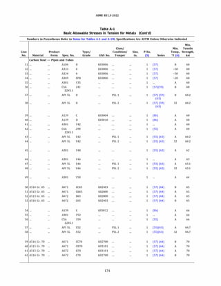
![ASME 831.3-2022
Table A-1
Basic Allowable Stresses in Tension for Metals (Cont'd)
Numbers in Parentheses Refer to Notes for Tables A-1 and A-lM; Specifications Are ASTM Unless Otherwise Indicated
Basic Allowable Stress, S, ksi, at Metal Temperature, 0
f [Notes (1), (2a)]
Min.Yield Max. Min.
Line Strength, Temp., Temp.
No. ksi Of to 100 200 300 400 500 600 650 700 750 800 850 900 950 1,000 1,050 1,100
Carbon Steel - Pipes and Tubes (Cont'd)
31 35 1,100 20.0 20.0 20.0 19.9 19.0 17.9 17.3 16.7 13.9 11.4 8.7 5.9 4.0 2.5 1.6 1.0
32 35 1,100 20.0 20.0 20.0 19.9 19.0 17.9 17.3 16.7 13.9 11.4 8.7 5.9 4.0 2.5 1.6 1.0
33 35 1,100 20.0 20.0 20.0 19.9 19.0 17.9 17.3 16.7 13.9 11.4 8.7 5.9 4.0 2.5 1.6 1.0
34 35 1,100 20.0 20.0 20.0 19.9 19.0 17.9 17.3 16.7 13.9 11.4 8.7 5.9 4.0 2.5 1.6 1.0
35 35 1,100 20.0 20.0 20.0 19.9 19.0 17.9 17.3 16.7 13.9 11.4 8.7 5.9 4.0 2.5 1.6 1.0
36 35 1,100 20.0 20.0 20.0 19.9 19.0 17.9 17.3 16.7 13.9 11.4 8.7 5.9 4.0 2.5 1.6 1.0
37 35.5 1,100 20.0 20.0 20.0 19.9 19.0 17.9 17.3 16.7 13.9 11.4 8.7 5.9 4.0 2.5 1.6 1.0
38 35.5 1,100 20.0 20.0 20.0 19.9 19.0 17.9 17.3 16.7 13.9 11.4 8.7 5.9 4.0 2.5 1.6 1.0
39 42 300 20.0 20.0 20.0
40 46 300 20.0 20.0 20.0
41 42 400 20.0 20.0 20.0 20.0
42 42 500 20.0 20.0 20.0 20.0 19.7
43 42.1 500 20.1 20.1 20.1 20.1 19.8
44 42.1 500 20.1 20.1 201 20.1 19.8
45 48 650 20.7 20.7 20.7 20.7 20.7 20.7 18.7
46 46 500 21.0 21.0 21.0 21.0
47 46.4 500 21.0 21.0 21.0 21.0 21.0
48 46.4 500 21.0 21.0 21.0 21.0 21.0
49 50 650 21.3 21.3 21.3 21.3 21.3 21.3 18.7
50 35 1,000 21.7 21.4 20.6 19.9 19.0 17.9 17.3 16.7 13.9 11.4 8.7 5.9 4.0 2.5
51 35 1,100 21.7 21.4 20.6 19.9 19.0 17.9 17.3 16.7 13.9 11.4 8.7 5.9 4.0 2.5 1.6 1.0
52 35 1,100 21.7 21.4 20.6 19.9 19.0 17.9 17.3 16.7 13.9 11.4 8.7 5.9 4.0 2.5 1.6 1.0
53 35 1,100 21.7 21.4 20.6 19.9 19.0 17.9 17.3 16.7 13.9 11.4 8.7 5.9 4.0 2.5 1.6 1.0
54 52 300 22.0 22.0 22.0
55 52 400 22.0 22.0 22.0 22.0
56 52 500 22.0 22.0 22.0 22.0 22.0
57 52.2 500 22.2 22.2 22.2 22.2 22.2
58 52.2 500 22.2 22.2 22.2 22.2 22.2
59 38 1,000 23.3 23.2 22.4 21.6 20.6 19.4 18.8 18.1 14.8 12.0 9.3 6.7 4.0 2.5
60 38 1,100 23.3 23.2 22.4 21.6 20.6 19.4 18.8 18.1 14.8 12.0 9.3 6.7 4.0 2.5 1.6 1.0
61 38 1,100 23.3 23.2 22.4 21.6 20.6 19.4 18.8 18.1 14.8 12.0 9.3 6.7 4.0 2.5 1.6 1.0
62 38 1,100 23.3 23.2 22.4 21.6 20.6 19.4 18.8 18.1 14.8 12.0 9.3 6.7 4.0 2.5 1.6 1.0
175](https://image.slidesharecdn.com/26162943-231229160810-282cb07a/85/ASME-B31-3-2022-Procces-piping-code-for-b31-3-202-320.jpg)
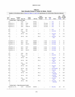
![ASME 831.3-2022
Table A-1
Basic Allowable Stresses in Tension for Metals (Cont'd)
Numbers in Parentheses Refer to Notes for Tables A-1 and A-lM; Specifications Are ASTM Unless Otherwise Indicated
Basic Allowable Stress, S, ksi, at Metal Temperature, 0
f [Notes (1), (2a)]
Min.Yield Max. Min.
Line Strength, Temp., Temp.
No. ksi Of to 100 200 300 400 500 600 650 700 750 800 850 900 950 1,000 1,050 1,100
Carbon Steel - Pipes and Tubes (Cont'd)
63 40 800 23.3 23.3 23.3 22.8 21.7 20.4 19.8 18.3 14.8 12.0 ...
64 50 700 23.3 23.3 22.8 22.7 22.7 22.4 21.9 18.3
65 50 700 23.3 23.3 22.8 22.7 22.7 22.4 21.9 18.3
66 50 700 23.3 23.3 22.8 22.7 22.7 22.4 21.9 18.3
67 56 400 23.7 23.7 23.7 23.7
68 56 500 23.7 23.7 23.7 23.7 23.7
69 56.6 500 23.7 23.7 23.7 23.7 23.7
70 56.6 500 23.7 23.7 23.7 23.7 23.7
71 40 1,100 25.0 24.4 23.6 22.8 21.7 20.4 19.8 19.1 15.7 12.6 9.3 6.7 4.0 2.5 1.6 1.0
72 40 1,100 25.0 24.4 23.6 22.8 21.7 20.4 19.8 19.1 15.7 12.6 9.3 6.7 4.0 2.5 1.6 1.0
73 40 1,100 25.0 24.4 23.6 22.8 21.7 20.4 19.8 19.1 15.7 12.6 9.3 6.7 4.0 2.5 1.6 1.0
74 42 700 25.0 25.0 24.8 23.9 22.8 21.5 20.8 19.6
75 42 700 25.0 25.0 24.8 23.9 22.8 21.5 20.8 19.6
76 42 700 25.0 25.0 24.8 23.9 22.8 21.5 20.8 19.6
77 60 400 25.0 25.0 25.0 25.0
78 60 500 25.0 25.0 25.0 25.0 25.0
79 60.2 500 25.1 25.1 25.1 25.1 25.1
80 60.2 500 25.1 25.1 25.1 25.1 25.1
81 65 500 25.7 25.7 25.7 25.7 25.7
82 65.3 500 25.9 25.9 25.9 25.9 25.9
83 65.3 500 25.9 25.9 25.9 25.9 25.9
84 70 400 27.3 27.3 27.3 27.3
85 70.3 400 27.6 27.6 27.6 27.6
86 70.3 400 27.6 27.6 27.6 27.6
87 80 400 30.0 30.0 30.0 30.0
88 80.5 400 30.2 30.2 30.2 30.2
Carbon Steel - Pipes (Structural Grade)
89 30 400 15.0 15.0 15.0 15.0
177](https://image.slidesharecdn.com/26162943-231229160810-282cb07a/85/ASME-B31-3-2022-Procces-piping-code-for-b31-3-204-320.jpg)
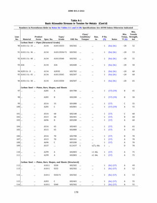
![ASME 831.3-2022
Table A-1
Basic Allowable Stresses in Tension for Metals (Cont'd)
Numbers in Parentheses Refer to Notes for Tables A-1 and A-lM; Specifications Are ASTM Unless Otherwise Indicated
Basic Allowable Stress, S, ksi, at Metal Temperature, 0
f [Notes (1), (2a)]
Min.Yield Max. Min.
Line Strength, Temp., Temp.
No. ksi Of to 100 200 300 400 500 600 650 700 750 800 850 900 950 1,000 1,050 1,100
Carbon Steel - Pipes (Structural Grade) (Cont'd)
90 33 400 15.9 15.9 15.9 15.9
91 36 400 16.3 16.3 16.3 16.3
92 40 400 16.9 16.9 16.9 16.9
93 36 400 17.8 17.8 17.8 17.8
94 33 300 18.4 18.4 17.9
95 45 400 18.4 18.4 18.4 18.4
96 so 400 19.9 19.9 19.9 19.9
Carbon Steel - Plates, Bars, Shapes, and Sheets
97 24 1,100 15.0 14.7 14.2 13.7 13.0 12.3 11.9 11.5 10.7 9.2 7.9 5.9 4.0 2.5 1.6 1.0
98 27 1,100 16.7 16.5 15.9 15.4 14.7 13.8 13.3 12.5 10.7 9.2 7.9 5.9 4.0 2.5 1.6 1.0
99 30 1,000 18.3 18.3 17.7 17.1 16.3 15.3 14.8 14.3 13.0 10.8 8.7 5.9 4.0 2.5
100 30 1,100 18.3 18.3 17.7 17.1 16.3 15.3 14.8 14.3 13.0 10.8 8.7 5.9 4.0 2.5 1.6 1.0
101 32 1,000 20.0 19.5 18.9 18.2 17.4 16.4 15.8 15.3 13.0 10.8 8.7 5.9 4.0 2.5
102 32 1,000 20.0 19.5 18.9 18.2 17.4 16.4 15.8 15.3 13.0 10.8 8.7 5.9 4.0 2.5
103 35 700 20.0 20.0 20.0 19.9 19.0 17.9 17.3 15.6
104 35 1,000 21.7 21.4 20.6 19.9 19.0 17.9 17.3 16.7 13.9 11.4 8.7 5.9 4.0 2.5
105 35 1,000 21.7 21.4 20.6 19.9 19.0 17.9 17.3 16.7 13.9 11.4 8.7 5.9 4.0 2.5
106 38 1,000 23.3 23.2 22.4 21.6 20.6 19.4 18.8 18.1 14.8 12.0 9.3 6.7 4.0 2.5
107 38 1,000 23.3 23.2 22.4 21.6 20.6 19.4 18.8 18.1 14.8 12.0 9.3 6.7 4.0 2.5
108 40 700 23.3 23.3 23.3 22.8 21.7 20.5 19.7 18.3
109 so 700 23.3 23.3 22.8 22.7 22.7 22.4 21.9 18.3
110 40 1,100 25.0 24.4 23.6 22.8 21.7 20.4 19.8 19.1 15.7 12.6 9.3 6.7 4.0 2.5 1.6 1.0
111 42 1,100 25.0 25.0 24.8 23.9 22.8 21.5 20.8 19.6 15.7 12.6 9.3 6.7 4.0 2.5 1.6 1.0
Carbon Steel - Plates, Bars, Shapes, and Sheets (Structural)
112 30 750 15.0 15.0 15.0 15.0 15.0 14.1 13.4 11.5 9.8
113 33 750 15.9 15.9 15.9 15.9 15.9 15.5 13.4 11.5 9.8
114 36 750 16.3 16.3 16.3 16.3 16.3 16.3 13.4 11.5 9.8
115 30 750 16.8 16.8 16.3 15.7 15.0 14.1 13.6 13.2 12.0
116 40 750 16.8 16.8 16.8 16.8 16.8 16.8 16.8 14.4 12.0
179](https://image.slidesharecdn.com/26162943-231229160810-282cb07a/85/ASME-B31-3-2022-Procces-piping-code-for-b31-3-206-320.jpg)
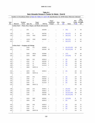
![ASME 831.3-2022
Table A-1
Basic Allowable Stresses in Tension for Metals (Cont'd)
Numbers in Parentheses Refer to Notes for Tables A-1 and A-lM; Specifications Are ASTM Unless Otherwise Indicated
Basic Allowable Stress, S, ksi, at Metal Temperature, °F [Notes (1), (2a)]
Min.Yield Max. Min.
Line Strength, Temp., Temp.
No. ksi Of to 100 200 300 400 500 600 650 700 750 800 850 900 950 1,000 1,050 1,100
Carbon Steel - Plates, Bars, Shapes, and Sheets (Structural) (Cont'd)
117 36 700 17.8 17.8 17.8 17.8 17.8 16.9 16.4 14.4
118 33 750 18.4 18.4 17.9 17.3 16.5 15.5 15.0 14.5 12.8
119 45 750 18.4 18.4 18.4 18.4 18.4 18.4 18.4 15.5 12.8
120 50 750 19.9 19.9 19.9 19.9 19.9 19.9 18.9 15.5 12.8
121 50 800 19.9 19.9 19.9 19.9 19.9 19.9 18.9 15.5 12.8 10.5 ...
Carbon Steel - Forgings and Fittings
122 30 1,000 20.0 18.3 17.7 17.1 16.3 15.3 14.8 14.3 13.8 11.4 8.7 5.9 4.0 2.5
123 30 1,100 20.0 18.3 17.7 17.1 16.3 15.3 14.8 14.3 13.8 11.4 8.7 5.9 4.0 2.5 1.6 1.0
124 35 1,000 20.0 20.0 20.0 19.9 19.0 17.9 17.3 16.7 13.9 11.4 8.7 5.9 4.0 2.5
125 35 1,100 20.0 20.0 20.0 19.9 19.0 17.9 17.3 16.7 13.9 11.4 8.7 5.9 4.0 2.5 1.6 1.0
126 42 500 20.0 20.0 20.0 20.0 19.7
127 42 500 20.0 20.0 20.0 20.0 19.7
128 42 500 20.0 20.0 20.0 20.0 19.7
129 42 500 20.0 20.0 20.0 20.0 19.7
130 42 500 20.0 20.0 20.0 20.0 19.7
131 46 500 21.0 21.0 21.0 21.0 21.0
132 46 500 21.0 21.0 21.0 21.0 21.0
133 52 500 22.0 22.0 22.0 22.0 22.0
134 52 500 22.0 22.0 22.0 22.0 22.0
135 52 500 22.0 22.0 22.0 22.0 22.0
136 52 500 22.0 22.0 22.0 22.0 22.0
137 52 500 22.0 22.0 22.0 22.0 22.0
138 36 1,000 23.3 22.0 21.2 20.5 19.6 18.4 17.8 17.2 14.8 12.0 9.3 6.7 4.0 2.5
139 36 1,000 23.3 22.0 21.2 20.5 19.6 18.4 17.8 17.2 14.8 12.0 9.3 6.7 4.0 2.5
140 36 1,100 23.3 22.0 21.2 20.5 19.6 18.4 17.8 17.2 14.8 12.0 9.3 6.7 4.0 2.5 1.6 1.0
141 36 1,100 23.3 22.0 21.2 20.5 19.6 18.4 17.8 17.2 14.8 12.0 9.3 6.7 4.0 2.5 1.6 1.0
142 40 800 23.3 23.3 23.3 22.8 21.7 20.4 19.8 18.3 14.8 12.0 ...
143 56 500 23.7 23.7 23.7 23.7 23.7
144 60 500 25.0 25.0 25.0 25.0 25.0
145 60 500 25.0 25.0 25.0 25.0 25.0
146 60 500 25.0 25.0 25.0 25.0 25.0
147 60 500 25.0 25.0 25.0 25.0 25.0
181](https://image.slidesharecdn.com/26162943-231229160810-282cb07a/85/ASME-B31-3-2022-Procces-piping-code-for-b31-3-208-320.jpg)
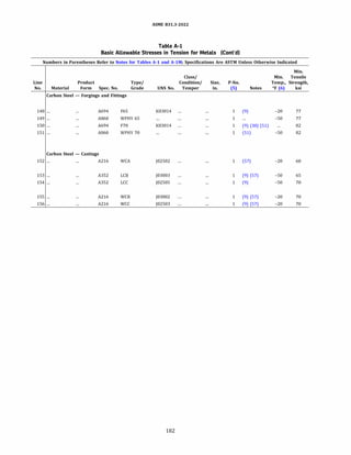
![ASME 831.3-2022
Table A-1
Basic Allowable Stresses in Tension for Metals (Cont'd)
Numbers in Parentheses Refer to Notes for Tables A-1 and A-lM; Specifications Are ASTM Unless Otherwise Indicated
Basic Allowable Stress, S, ksi, at Metal Temperature, °F [Notes (1), (2a)]
Min.Yield Max. Min.
Line Strength, Temp., Temp.
No. ksi Of to 100 200 300 400 500 600 650 700 750 800 850 900 950 1,000 1,050 1,100
Carbon Steel - Forgings and Fittings (Cont'd)
148 65 500 25.7 25.7 25.7 25.7 25.7
149 65 500 25.7 25.7 25.7 25.7 25.7
150 70 400 27.3 27.3 27.3 27.3
151 70 400 27.3 27.3 27.3 27.3
Carbon Steel - Castings
152 30 1,100 20.0 18.3 17.7 17.1 16.3 15.3 14.8 14.3 13.8 11.4 8.7 5.9 4.0 2.5 1.6 1.0
153 35 1,100 21.7 21.4 20.6 19.9 19.0 17.9 17.3 16.7 13.9 11.4 9.0 6.3 4.0 2.5 1.6 1.0
154 40 700 23.3 23.3 23.3 22.8 21.7 20.4 19.8 19.2
155 36 1,100 23.3 22.0 21.2 20.5 19.6 18.4 17.8 17.2 14.8 12.0 9.3 6.7 4.0 2.5 1.6 1.0
156 40 1,000 23.3 23.3 23.3 22.8 21.7 20.4 19.8 18.3 14.8 12.0 9.3 6.7 4.0 2.5
183](https://image.slidesharecdn.com/26162943-231229160810-282cb07a/85/ASME-B31-3-2022-Procces-piping-code-for-b31-3-210-320.jpg)
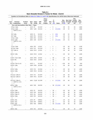
![ASME 831.3-2022
Table A-1
Basic Allowable Stresses in Tension for Metals (Cont'd)
Numbers in Parentheses Refer to Notes for Tables A-1 and A-lM; Specifications Are ASTM Unless Otherwise Indicated
Basic Allowable Stress, S, ksi, at Metal Temperature, °F [Notes (1), (2a)]
Min.
Line Temp.
No. to 100 200 300 400 500 600 650 700 750 800 850 900 950 1,000 1,050 1,100 1,150 1,200
Low and Intermediate Alloy Steel - Pipes
1 18.3 18.3 18.0 17.4 16.9 16.4 16.1 15.7 15.4 14.9 14.5 13.9 9.2 5.9
2 18.3 18.3 18.3 18.3 18.3 18.0 17.7 17.3 16.9 16.4 15.9 14.3 9.2 5.9
3 18.3 18.3 18.0 17.4 16.9 16.4 16.1 15.7 15.4 14.9 14.5 13.7 8.2 4.8 4.0 2.4
4 18.3 18.3 18.0 17.4 16.9 16.4 16.1 15.7 15.4 14.9 14.5 13.7 8.2 4.8 4.0 2.4
5 18.3 18.3 18.0 17.4 16.9 16.4 16.1 15.7 15.4 14.9 14.5 13.9 9.2 5.9 4.1 2.5
6 18.3 18.3 17.6 17.6 17.2 16.8 16.5 16.3 16.0 15.7 15.4 15.0 11.3 7.2 4.5 2.8 1.8 1.1
7 20.0 18.8 18.0 17.4 16.9 16.4 16.1 15.7 15.4 14.9 14.5 13.9 9.2 5.9 4.0 2.4
8 20.0 18.8 18.2 17.7 17.3 16.8 16.6 16.3 15.9 15.4 13.8 12.5 10.0 6.3 4.0 2.4
9 20.0 18.8 18.2 17.7 17.3 16.8 16.6 16.3 15.9 15.4 13.8 12.5 10.0 6.3 4.0 2.4
10 20.0 18.1 17.0 16.2 15.7 15.2 15.0 14.8 14.6 14.3 14.0 13.6 11.3 7.2 4.5 2.8 1.8 1.1
11 20.0 18.1 17.4 17.2 17.1 16.8 16.6 16.3 15.9 15.4 14.3 10.9 8.0 5.8 4.2 2.9 1.8 1.0
12 20.0 18.7 18.2 18.0 17.9 17.9 17.9 17.9 17.9 17.7 16.0 12.0 9.0 7.0 5.5 4.0 2.7 1.5
13 20.0 19.1 18.2 17.3 16.4 15.5 15.0
14 20.0 18.7 18.2 18.0 17.9 17.9 17.9 17.9 17.9 17.7 17.5 12.5 10.0 6.2 4.2 2.6 1.4 1.0
15 20.0 19.3 18.1 17.3 16.7 16.3 16.0 15.8 15.5 15.3 14.9 14.5 11.3 7.2 4.5 2.8 1.8 1.1
16 20.0 19.3 18.1 17.3 16.7 16.3 16.0 15.8 15.5 15.3 14.9 14.5 11.3 7.2 4.5 2.8 1.8 1.1
17 20.0 18.5 17.6 16.8 16.2 15.7 15.4 15.1 14.8 14.4 14.0 13.6 9.3 6.3 4.2 2.8 1.9 1.2
18 20.0 18.5 17.6 16.8 16.2 15.7 15.4 15.1 14.8 14.4 14.0 13.6 9.3 6.3 4.2 2.8 1.9 1.2
19 20.0 20.0 20.0 19.6 18.9 18.3 18.0 17.6 17.2 16.8 16.4 13.7 9.3 6.3 4.2 2.8 1.9 1.2
20 20.0 18.1 17.4 17.2 17.1 16.8 16.6 16.3 15.9 15.4 14.3 10.9 8.0 5.8 4.2 2.9 1.8 1.0
21 20.0 18.1 17.4 17.2 17.1 16.8 16.6 16.3 15.9 15.4 14.3 10.9 8.0 5.8 4.2 2.9 1.8 1.0
22 20.0 18.1 17.4 17.2 17.1 16.8 16.6 16.3 15.9 15.4 14.3 10.9 8.0 5.8 4.2 2.9 1.8 1.0
23 20.0 18.1 17.4 17.2 17.1 16.8 16.6 16.3 15.9 15.4 14.3 10.9 8.0 5.8 4.2 2.9 1.8 1.0
24 20.0 18.1 17.4 17.2 17.1 16.8 16.6 16.3 15.9 15.4 14.3 10.9 8.0 5.8 4.2 2.9 1.8 1.0
25 20.0 18.1 17.4 17.2 17.1 16.8 16.6 16.3 15.9 15.4 14.8 14.1 10.6 7.4 5.0 3.3 2.2 1.5
26 20.0 18.1 17.4 17.2 17.1 16.8 16.6 16.3 15.9 15.4 14.8 14.1 10.6 7.4 5.0 3.3 2.2 1.5
27 20.0 18.1 17.4 17.2 17.1 16.8 16.6 16.3 15.9 15.4 14.8 14.1 10.6 7.4 5.0 3.3 2.2 1.5
28 20.0 18.7 18.2 18.0 17.9 17.9 17.9 17.9 17.9 17.7 16.0 12.0 9.0 7.0 5.5 4.0 2.7 1.5
185](https://image.slidesharecdn.com/26162943-231229160810-282cb07a/85/ASME-B31-3-2022-Procces-piping-code-for-b31-3-212-320.jpg)
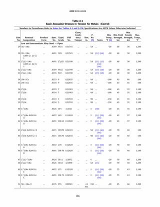
![ASME 831.3-2022
Table A-1
Basic Allowable Stresses in Tension for Metals (Cont'd)
Numbers in Parentheses Refer to Notes for Tables A-1 and A-lM; Specifications Are ASTM Unless Otherwise Indicated
Basic Allowable Stress, S, ksi, at Metal Temperature, °F [Notes (1), (2a)]
Min.
Line Temp.
No. to 100 200 300 400 500 600 650 700 750 800 850 900 950 1,000 1,050 1,100 1,150 1,200
Low and Intermediate Alloy Steel - Pipes (Cont'd)
29 20.0 18.7 18.2 18.0 17.9 17.9 17.9 17.9 17.9 17.7 16.0 12.0 9.0 7.0 5.5 4.0 2.7 1.5
30 20.0 18.5 18.2 18.0 17.9 17.9 17.9 17.9 17.9 17.7 16.0 12.0 9.0 7.0 5.5 4.0 2.7 1.5
31 20.0 18.7 18.2 18.0 17.9 17.9 17.9 17.9 17.9 17.7 17.1 13.6 10.8 8.0 5.7 3.8 2.4 1.4
32 20.0 18.7 18.2 18.0 17.9 17.9 17.9 17.9 17.9 17.7 17.1 13.6 10.8 8.0 5.7 3.8 2.4 1.4
33 20.0 18.7 18.2 18.0 17.9 17.9 17.9 17.9 17.9 17.7 17.1 13.6 10.8 8.0 5.7 3.8 2.4 1.4
34 21.0
35 21.0
36 21.7 21.4 20.6 19.9 18.9 17.5 16.7 15.7 13.9 11.4 9.0 6.5 4.5 2.5 1.6 1.0
37 21.7 21.4 20.6 19.9 18.9 17.5 16.7 15.7 13.9 11.4 9.0 6.5 4.5 2.5 1.6 1.0
38 21.7 21.4 20.6 19.9 18.9 17.5 16.7 15.7 13.9 11.4 9.0 6.5 4.5 2.5 1.6 1.0
39 21.7 21.4 20.6 19.9 18.9 17.5 16.7 15.7 13.9 11.4 9.0 6.5 4.5 2.5 1.6 1.0
40 21.7 21.7 21.0 20.3 19.7 19.1 18.7 18.4 17.9 17.4 16.9 13.7 8.2 4.8 4.0 2.4
41 21.7 21.7 21.7 21.5 20.8 20.2 19.8 19.4 19.0 18.4 17.9 13.7 8.2 4.8 4.0 2.4
42 21.7 21.7 21.7 21.5 20.8 20.2 19.8 19.4 19.0 18.4 17.9 13.7 8.2 4.8 4.0 2.4
43 23.3
44 23.3
45 23.3 23.3 23.3 23.2 22.5 21.8 21.4 21.0 20.5 19.9 19.3 13.7 8.2 4.8 4.0 2.4
46 23.3 23.3 23.3 23.2 22.5 21.8 21.4 21.0 20.5 19.9 19.3 13.7 8.2 4.8 4.0 2.4
47 23.3 23.3 23.3 22.5 21.7 20.9 20.5 20.1 19.7 19.2 18.7 13.7 9.3 6.3 4.2 2.8 1.9 1.2
48 23.3 23.3 22.6 22.6 22.6 22.6 22.6 22.6 22.6 22.6 21.9 15.8 11.4 7.8 5.1 3.2 2.0 1.2
49 25.0 25.0 25.0 25.0 24.2 23.4 23.0 22.6 22.0 21.4 20.7 13.7 8.2 4.8 4.0 2.4
50 25.0 25.0 25.0 25.0 24.2 23.4 23.0 22.6 22.0 21.4 20.7 13.7 8.2 4.8 4.0 2.4
51 28.3 28.3 28.3 28.2 28.1 27.7 27.3 26.7 25.9 24.9 23.7 22.3 20.7 18.0 14.0 10.3 7.0 4.3
187](https://image.slidesharecdn.com/26162943-231229160810-282cb07a/85/ASME-B31-3-2022-Procces-piping-code-for-b31-3-214-320.jpg)
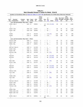
![ASME 831.3-2022
Table A-1
Basic Allowable Stresses in Tension for Metals (Cont'd)
Numbers in Parentheses Refer to Notes for Tables A-1 and A-lM; Specifications Are ASTM Unless Otherwise Indicated
Basic Allowable Stress, S, ksi, at Metal Temperature, °F [Notes (1), (2a)]
Min.
Line Temp.
No. to 100 200 300 400 500 600 650 700 750 800 850 900 950 1,000 1,050 1,100 1,150 1,200
Low and Intermediate Alloy Steel - Pipes (Cont'd)
52 28.3 28.3 28.3 28.2 28.1 27.7 27.3 26.7 25.9 24.9 23.7 22.3 20.7 18.0 14.0 10.3 7.0 4.3
53 30.0 29.9 29.1 28.8 28.7 28.3 27.9 27.3 26.5 25.5 24.2 16.4 11.0 7.4 5.0 3.3 2.2 1.5
54 30.0 29.9 29.1 28.8 28.7 28.3 27.9 27.3 26.5 25.5 24.2 16.4 11.0 7.4 5.0 3.8 2.2 1.5
55 33.3 33.3
56 33.3 33.3
Low and Intermediate Alloy Steel - Plates
57 18.3 18.3 18.3 18.3 18.3 18.0 17.7 17.3 16.9 16.4 15.9 14.3 9.2 5.9
58 18.3 18.0 17.6 17.6 17.2 16.8 16.5 16.3 16.0 15.7 15.4 15.0 11.3 7.2 4.5 2.8 1.8 1.1
59 20.0 18.1 17.4 17.2 17.1 16.8 16.6 16.3 15.9 15.4 14.8 14.1 10.6 7.4 5.0 3.3 2.2 1.5
60 20.0 20.0 20.0 19.6 18.9 18.3 18.0 17.6 17.2 16.8 16.4 13.7 9.3 6.3 4.2 2.8 1.9 1.2
61 20.0 18.1 17.4 17.2 17.1 16.8 16.6 16.3 15.9 15.4 14.3 10.9 8.0 5.8 4.2 2.9 1.8 1.0
62 20.0 18.3 17.5 17.0 16.6 16.2 16.0 15.8 15.5 15.2 14.9 12.0 9.0 7.0 5.5 4.0 2.7 1.5
63 20.0 18.7 18.2 18.0 17.9 17.9 17.9 17.9 17.9 17.7 17.1 13.6 10.8 8.0 5.7 3.8 2.4 1.4
64 21.7 21.7 21.7 21.1 20.0 18.5 17.6 16.6 13.9 11.4 9.0 6.5 4.5 2.5
65 21.7 21.7 21.7 21.1 20.0 18.5 17.6 16.6 13.9 11.4 9.0 6.5 4.5 2.5
66 21.7 21.7 21.7 21.5 20.8 20.2 19.8 19.4 19.0 18.4 17.9 13.7 8.2 4.8 4.0 2.4
67 21.7 21.3 20.8 20.8 20.8 20.3 20.0 19.7 19.4 19.1 18.6 18.0 11.3 7.2 4.5 2.8 1.8 1.1
68 23.3 23.3 23.3 22.8 21.6 20.0 19.0 16.9 13.9 11.4 9.0 6.5 4.5 2.5
69 23.3 23.3 23.3 22.8 21.6 20.0 19.0 18.0 14.8 12.0 9.3 6.5 4.5 2.5
70 23.3 23.3 23.3 23.3 23.3 23.3 23.3 23.3 23.1 22.4 21.7 20.9 9.2 5.9
71 23.3 23.3 23.3 23.2 22.5 21.8 21.4 21.0 20.5 19.9 19.3 13.7 8.2 4.8 4.0 2.4
72 25.0 25.0 25.0 25.0 25.0 25.0 24.9 24.4 23.9 23.2 20.0 13.7 8.2 4.8
73 25.0 25.0 25.0 25.0 24.2 23.4 23.0 22.6 22.0 21.4 20.7 13.7 8.2 4.8 4.0 2.4
74 25.0 25.0 25.0 25.0 24.4 23.5 23.1 22.6 22.2 21.6 20.2 13.7 9.3 6.3 4.2 2.8 1.9 1.2
75 25.0 24.9 24.2 24.0 24.0 23.6 23.2 22.7 16.5 16.0 15.1 10.9 8.0 5.8 4.2 2.9 1.8 1.0
76 25.0 25.0 24.2 24.2 24.2 24.2 24.2 24.2 24.2 24.2 18.1 13.1 9.5 6.8 4.9 3.2 2.4 1.3
77 25.0 25.0 24.3 24.1 24.0 23.8 23.6 23.4 23.0 22.5 21.9 15.8 11.4 7.8 5.1 3.2 2.0 1.2
78 26.7 26.7 26.7 26.7 26.7 26.7 26.7 26.7 26.5 25.7 20.0 13.7 8.2 4.8
79 26.7 26.7 26.7 26.7 26.7 26.7 26.7 26.7 26.5 25.7 20.0 13.7 8.2 4.8
80 26.7 26.7 26.7 26.7 26.7 26.7 26.7 26.7 26.5 25.7 20.0 13.7 8.2 4.8
81 28.3 28.3 28.3 28.2 28.1 27.7 27.3 26.7 25.9 24.9 23.7 22.3 20.7 18.0 14.0 10.3 7.0 4.3
189](https://image.slidesharecdn.com/26162943-231229160810-282cb07a/85/ASME-B31-3-2022-Procces-piping-code-for-b31-3-216-320.jpg)
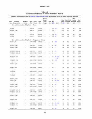
![ASME 831.3-2022
Table A-1
Basic Allowable Stresses in Tension for Metals (Cont'd)
Numbers in Parentheses Refer to Notes for Tables A-1 and A-lM; Specifications Are ASTM Unless Otherwise Indicated
Basic Allowable Stress, S, ksi, at Metal Temperature, °F [Notes (1), (2a)]
Min.
Line Temp.
No. to 100 200 300 400 500 600 650 700 750 800 850 900 950 1,000 1,050 1,100 1,150 1,200
Low and Intermediate Alloy Steel - Plates (Cont'd)
82 33.3
83 31.7 31.7
84 33.3 33.3
85 33.3 33.3
Low and Intermediate Alloy Steel - Forgings and Fittings
86 18.3 18.3 18.0 17.4 16.9 16.4 16.1 15.7 15.4 14.9 14.5 13.7 8.2 4.8 4.0 2.4
87 20.0 19.3 18.1 17.3 16.7 16.3 16.0 15.8 15.5 15.3 14.9 14.5 11.3 7.2 4.5 2.8 1.8 1.1
88 20.0 19.3 18.1 17.3 16.7 16.3 16.0 15.8 15.5 15.3 14.9 14.5 11.3 7.2 4.5 2.8 1.8 1.1
89 20.0 18.5 17.6 16.8 16.2 15.7 15.4 15.1 14.8 14.4 14.0 13.6 9.3 6.3 4.2 2.8 1.9 1.2
90 20.0 18.5 17.6 16.8 16.2 15.7 15.4 15.1 14.8 14.4 14.0 13.6 9.3 6.3 4.2 2.8 1.9 1.2
91 20.0 18.7 18.2 18.0 17.9 17.9 17.9 17.9 17.9 17.7 17.1 13.6 10.8 8.0 5.7 3.8 2.4 1.4
92 20.0 18.7 18.2 18.0 17.9 17.9 17.9 17.9 17.9 17.7 17.1 13.6 10.8 8.0 5.7 3.8 2.4 1.4
93 20.0 18.1 17.4 17.2 17.1 16.8 16.6 16.3 15.9 15.4 14.3 10.9 8.0 5.8 4.2 2.9 1.8 1.0
94 20.0 18.1 17.4 17.2 17.1 16.8 16.6 16.3 15.9 15.4 14.8 14.1 11.0 7.4 5.0 3.3 2.2 1.5
95 21.7 21.4 20.6 19.9 18.9 17.5 16.7
96 23.3 22.9 22.1 21.4 20.3 18.8 17.9
97 23.3 23.3 23.3 23.2 22.5 21.8 21.4 21.0 20.5 19.9 19.3 18.6 9.2 5.9
98 23.3 23.3 23.3 23.2 22.5 21.8 21.4 21.0 20.5 19.9 19.3 13.7 8.2 4.8 4.0 2.4
99 23.3 22.9 22.4 21.7 20.9 20.3 20.0 19.7 19.4 19.1 18.6 18.0 11.3 7.2 4.5 2.8 1.8 1.1
100 23.3 22.9 22.4 21.7 20.9 20.3 20.0 19.7 19.4 19.1 18.6 18.0 11.3 7.2 4.5 2.8 1.8 1.1
101 23.3 23.3 23.3 22.5 21.7 20.9 20.5 20.1 19.7 19.2 18.7 13.7 9.3 6.3 4.2 2.8 1.9 1.2
102 23.3 23.3 23.3 22.5 21.7 20.9 20.5 20.1 19.7 19.2 18.7 13.7 9.3 6.3 4.2 2.8 1.9 1.2
103 23.3 23.3 22.6 22.4 22.4 22.0 21.7 21.2 20.6 19.8 14.3 10.9 8.0 5.8 4.2 2.9 1.8 1.0
104 25.0 25.0 24.3 24.1 24.0 23.8 23.6 23.4 23.0 22.5 18.1 13.1 9.5 6.8 4.9 3.2 2.4 1.3
105 25.0 25.0 24.2 24.2 24.2 24.2 24.2 24.2 24.2 24.2 21.9 15.8 11.4 7.8 5.1 3.2 2.0 1.2
106 25.0 25.0 24.2 24.2 24.2 24.2 24.2 24.2 24.2 24.2 21.9 15.8 11.4 7.8 5.1 3.2 2.0 1.2
107 28.3 28.3 27.4 27.2 27.1 26.8 26.3 25.8 25.0 24.0 22.9 15.2 10.6 7.4 5.0 3.3 2.2 1.5
191](https://image.slidesharecdn.com/26162943-231229160810-282cb07a/85/ASME-B31-3-2022-Procces-piping-code-for-b31-3-218-320.jpg)
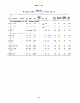
![ASME 831.3-2022
Table A-1
Basic Allowable Stresses in Tension for Metals (Cont'd)
Numbers in Parentheses Refer to Notes for Tables A-1 and A-lM; Specifications Are ASTM Unless Otherwise Indicated
Basic Allowable Stress, S, ksi, at Metal Temperature, °F [Notes (1), (2a)]
Min.
Line Temp.
No. to 100 200 300 400 500 600 650 700 750 800 850 900 950 1,000 1,050 1,100 1,150 1,200
Low and Intermediate Alloy Steel - Forgings and Fittings (Cont'd)
108 28.3 28.3 28.3 28.2 28.1 27.7 27.3 26.7 25.9 24.9 23.7 22.3 20.7 18.0 14.0 10.3 7.0 4.3
109 28.3 28.3 28.3 28.2 28.1 27.7 27.3 26.7 25.9 24.9 23.7 22.3 20.7 18.0 14.0 10.3 7.0 4.3
110 30.0 29.9 29.1 28.8 28.7 28.3 27.9 27.3 26.5 25.5 14.3 10.9 8.0 5.8 4.2 2.9 1.8 1.0
111 33.3 33.3
Low and Intermediate Alloy Steel - Castings
112 21.7 21.7 21.0 20.3 19.7 19.1 18.7 18.4
113 21.7 21.7 21.0 20.3 19.7 19.1 18.7 18.4 17.9 17.4 16.9 13.7 8.2 4.8 4.0 2.4
114 23.3 23.3 23.3 22.8 21.6 20.0 19.0
115 23.3 23.3 23.3 22.8 21.6 20.0 19.0
116 23.3 23.3 23.3 23.3 23.0 22.4 22.1 21.7 21.2 20.6 19.8 14.3 9.2 5.9
117 23.3 23.3 23.3 23.3 23.0 22.4 22.1 21.7 21.2 20.6 19.8 14.3 9.2 5.9 4.0 2.4
118 23.3 23.3 23.3 22.5 21.7 20.9 20.5 20.1 19.7 19.2 18.7 13.7 9.3 6.3 4.2 2.8 1.9 1.2
119 23.3 23.3 22.6 22.6 22.6 22.6 22.6 22.6 22.6 22.6 21.9 15.8 11.4 7.8 5.1 3.2 2.0 1.2
120 30.0 29.9 29.1 28.8 28.7 28.3 27.9 27.3 26.5 25.5 14.3 10.9 8.0 5.8 4.2 2.9 1.8 1.0
121 30.0 29.9 29.1 28.8 28.7 28.3 27.9 27.3 26.5 25.5 24.2 15.2 10.6 7.4 5.0 3.3 2.2 1.5
193](https://image.slidesharecdn.com/26162943-231229160810-282cb07a/85/ASME-B31-3-2022-Procces-piping-code-for-b31-3-220-320.jpg)
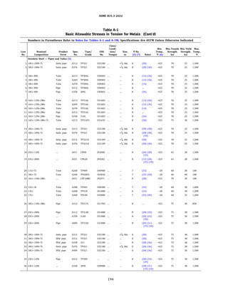
![ASME 831.3-2022
Table A-1
Basic Allowable Stresses in Tension for Metals (Cont'd)
Numbers in Parentheses Refer to Notes for Tables A-1 and A-lM; Specifications Are ASTM Unless Otherwise Indicated
Min.
Line Temp.
Basic Allowable Stress, S, ksi, at Metal Temperature, °F [Notes (1). (2a)]
No. to 100 200 300 400 500 600 650 700 750 800 850 900 950 1,000 1,050 1,100 1,150 1,200 1,250 1,300 1,350 1,400 1,450 1,500
16.7 16.7 16.7 16.7 16.1 15.2 14.9 14.6 14.3 14.1 13.9 13.8 13.6 13.5 9.6
16.7 16.7 16.7 16.7 16.1 15.2 14.9 14.6 14.3 14.1 13.9 13.8 13.6 13.5 9.6
16.7 16.7 16.7 15.8 14.7 14.0 13.7 13.5 13.3 13.0 12.8 12.6 12.3 12.0 6.3
6.9
6.9
5.1
4 16.7 16.7 16.7 15.8 14.7 14.0 13.7 13.5 13.3 13.0 12.8 12.6 12.3 12.0 6.3 5.1
5 16.7 16.7 16.7 15.8 14.7 14.0 13.7 13.5 13.3 13.0 12.8 12.6 12.3 12.0 6.3 5.1
6 16.7 16.7 16.7 15.8 14.7 14.0 13.7 13.5 13.3 13.0 12.8 12.6 12.3 12.0 6.3 5.1
7 16.7 16.7 16.7 15.8 14.7 14.0 13.7 13.5 13.3 13.0 12.8 12.6 12.3 12.0 6.3 5.1
8 16.7 16.7 16.7 15.7 14.8 14.0 13.7 13.5 13.2 12.9 12.7 12.4 12.1 11.8 11.6 11.4
9 16.7 16.7 16.7 15.7 14.8 14.0 13.7 13.5 13.2 12.9 12.7 12.4 12.1 11.8 11.6 11.4
10 16.7 16.7 16.7 15.7 14.8 14.0 13.7 13.5 13.2 12.9 12.7 12.4 12.1 11.8 11.6 11.4
11 16.7 16.7 16.7 15.7 14.8 14.0 13.7 13.5 13.2 12.9 12.7 12.4 12.1 11.8 11.6 11.4
12 16.7 16.7 16.7 15.7 14.8 14.0 13.7 13.5 13.2 12.9 12.7 12.4 12.1 11.8 11.6 11.4
13 20.0 20.0 20.0 19.3 17.8 16.8 16.5 16.2 16.1 15.9 15.8 15.7 15.5 15.3 15.1 12.3
14 16.7 16.7 16.7 16.7 16.1 15.2 14.9 14.6 14.3 14.1 13.9 13.8 13.6 13.5 12.3 9.1
15 16.7 16.7 16.7 16.7 16.1 15.2 14.9 14.6 14.3 14.1 13.9 13.8 13.6 13.5 12.3 9.1
16 16.7 16.7 16.7 16.7 16.1 15.2 14.9 14.6 14.3 14.1 13.9 13.8 13.6 13.5 12.3 9.1
17 16.7 16.7 16.7 16.7 16.1 15.2 14.9 14.6 14.3 14.1 13.9 13.8 13.6 13.5 12.3 9.1
18 18.7 18.7 18.5 18.0 17.7 17.1 16.7 16.3 15.9 15.4 14.9 14.4 13.9 11.1 8.5 6.5
19 18.7 18.7 18.5 18.0 17.7 17.1 16.7 16.3 15.9 15.4 14.9 14.4 13.9 11.3 9.8 8.5
20 20.0
21 20.0
22 20.0
23 20.0 20.0 19.6 19.3 19.0 18.5 18.1 17.7 17.1 16.4 15.6 14.3 8.4 4.0
24 20.0 20.0 19.6 19.3 19.0 18.5 18.1 17.7 17.1 16.4 15.6 12.3 8.8 6.4 4.4
25 20.0 20.0 19.6 19.3 19.0 18.5 18.1 17.7 17.1 16.4 15.6 12.0 9.2 6.5 4.5
26 20.0 20.0 20.0 18.9 17.7 16.9 16.5 16.2 15.8 15.5 15.2 ...
27 20.0 20.0 20.0 20.0 19.3 18.5 18.2 17.9 17.7 17.4 17.2 16.9 15.9 9.9
28 20.0 20.0 20.0 20.0 19.3 18.5 18.2 17.9 17.7 17.4 17.2 16.9 15.9 9.9
29 20.0 20.0 20.0 20.0 19.3 18.5 18.2 17.9 17.7 17.4 17.2 16.9 15.9 9.9
7.1
7.1
7.1
30 20.0 20.0 20.0 20.0 19.3 18.3 17.8 17.5 17.2 16.9 16.7 16.5 16.4 16.2 9.6
31 20.0 20.0 20.0 20.0 19.3 18.3 17.8 17.5 17.2 16.9 16.7 16.5 16.4 16.2 9.6
32 20.0 20.0 20.0 20.0 19.3 18.3 17.8 17.5 17.2 16.9 16.7 16.5 16.4 16.2 9.6
33 20.0 20.0 20.0 20.0 19.3 18.3 17.8 17.5 17.2 16.9 16.7 16.5 16.4 16.2 9.6
34 20.0 20.0 20.0 20.0 19.3 18.3 17.8 17.5 17.2 16.9 16.7 16.5 16.4 16.2 9.6
35 20.0 20.0 20.0 20.0 19.4 18.8 18.5 18.2 18.0 17.7 17.5 17.2 16.9 13.8 10.3
36 20.0 20.0 20.0 20.0 19.4 18.8 18.5 18.2 18.0 17.7 17.5 17.2 16.9 13.8 10.3
195
2.9
3.2
5.0
5.0
5.0
6.9
6.9
6.9
6.9
6.9
7.6
7.6
5.0 3.6
5.0 3.6
4.0 3.2
4.0 3.2
4.0 3.2
4.0 3.2
4.0 3.2
8.8 6.4
8.8 6.4
8.8 6.4
8.8 6.4
8.8 6.4
9.8 7.4
6.9 5.4
6.9 5.4
6.9 5.4
6.9 5.4
5.0 3.8
7.3 6.0
1.8 1.0
2.4 1.8
3.6 2.5
3.6 2.5
3.6 2.5
5.0 3.6
5.0 3.6
5.0 3.6
5.0 3.6
5.0 3.6
5.5 4.0
5.5 4.0
Stainless Steel - Pipes and Tubes (3)
2.6
2.6
2.6
2.6
2.6
2.6
2.6
4.7
4.7
4.7
4.7
4.7
5.5
4.1
4.1
4.1
4.1
2.9
4.8
1.5
1.5
1.5
2.6
2.6
2.6
2.6
2.6
3.0
3.0
1.7
1.7
2.1
2.1
2.1
2.1
2.1
3.5
3.5
3.5
3.5
3.5
4.1
3.2
3.2
3.2
3.2
2.3
3.5
0.8
0.8
0.8
1.7
1.7
1.7
1.7
1.7
2.2
2.2
1.1
1.1
1.7
1.7
1.7
1.7
1.7
2.5
2.5
2.5
2.5
2.5
3.1
2.5
2.5
2.5
2.5
1.8
2.4
0.5
0.5
0.5
1.1
1.1
1.1
1.1
1.1
1.7
1.7
0.8
0.8
1.1
1.1
1.1
1.1
1.1
1.8
1.8
1.8
1.8
1.8
2.3
1.9
1.9
1.9
1.9
1.3
1.6
0.4
0.4
0.4
0.8
0.8
0.8
0.8
0.8
1.3
1.3
0.5
0.5
1.0
1.0
1.0
1.0
1.0
1.3
1.3
1.3
1.3
1.3
1.7
1.5
1.5
1.5
1.5
0.9
1.1
0.3
0.3
0.3
0.5
0.5
0.5
0.5
0.5
1.0
1.0
0.3
0.3
0.9
0.9
0.9
0.9
0.9
1.0
1.0
1.0
1.0
1.0
1.3
1.1
1.1
1.1
1.1
0.8
0.8
0.2
0.2
0.2
0.3
0.3
0.3
0.3
0.3
0.8
0.8](https://image.slidesharecdn.com/26162943-231229160810-282cb07a/85/ASME-B31-3-2022-Procces-piping-code-for-b31-3-222-320.jpg)
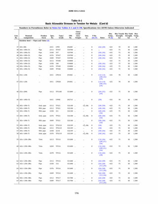
![ASME 831.3-2022
Table A-1
Basic Allowable Stresses in Tension for Metals (Cont'd)
Numbers in Parentheses Refer to Notes for Tables A-1 and A-lM; Specifications Are ASTM Unless Otherwise Indicated
Min.
Line Temp.
Basic Allowable Stress, S, ksi, at Metal Temperature, °F [Notes (1). (2a)]
No. to 100 200 300 400 500 600 650 700 750 800 850 900 950 1,000 1,050 1,100 1,150 1,200 1,250 1,300 1,350 1,400 1,450 1,500
37 20.0 20.0 20.0 18.6 17.5 16.6 16.2 15.8 15.5 15.2 14.9 14.6 14.3 12.2 9.5
38 20.0 20.0 20.0 20.0 20.0 19.3 19.0 18.7 18.5 18.3 18.2 18.1 18.1 16.0 12.1
39 20.0 20.0 20.0 20.0 20.0 19.3 19.0 18.7 18.5 18.3 18.2 18.1 18.1 16.0 12.1
40 20.0 20.0 20.0 20.0 20.0 19.3 19.0 18.7 18.5 18.3 18.2 18.1 18.1 16.0 12.1
41 20.0 20.0 20.0 20.0 20.0 19.3 19.0 18.7 18.5 18.3 18.2 18.1 18.1 16.0 12.1
42 20.0 20.0 20.0 20.0 20.0 19.3 19.0 18.7 18.5 18.3 18.2 18.1 18.1 16.0 12.1
43 20.0 20.0 20.0 20.0 20.0 19.3 19.0 18.7 18.5 18.3 18.2 18.1 18.1 16.0 12.1
44 20.0 20.0 20.0 20.0 20.0 19.3 19.0 18.7 18.5 18.3 18.2 18.1 18.1 16.0 12.1
45 20.0 20.0 20.0 20.0 20.0 19.3 19.0 18.7 18.5 18.3 18.2 18.1 18.1 16.0 12.1
7.5
9.1
9.1
9.1
9.1
9.1
9.1
9.1
9.1
46 20.0 20.0 19.9 19.4 18.9 18.3 17.9 17.5 17.0 16.5 16.0 15.4 14.9 11.1 8.5 6.5
47 20.0 20.0 19.9 19.4 18.9 18.3 17.9 17.5 17.0 16.5 16.0 15.4 14.9 11.1 8.5 6.5
48 20.0 20.0 20.0 20.0 19.3 18.5 18.2 17.9 17.7 17.4 17.2 16.9 16.7 13.8 10.3 7.6
49 20.0 20.0 20.0 18.6 17.5 16.6 16.2 15.8 15.5 15.2 14.9 14.6 14.3 14.0 12.1 9.1
so 20.0 20.0 20.0 20.0 19.3 18.3 17.8 17.5 17.2 16.9 16.7 16.5 16.4 16.2 12.3 9.1
51 20.0 20.0 20.0 20.0 19.3 18.3 17.8 17.5 17.2 16.9 16.7 16.5 16.4 16.2 12.3 9.1
52 20.0 20.0 20.0 20.0 19.3 18.3 17.8 17.5 17.2 16.9 16.7 16.5 16.4 16.2 12.3 9.1
53 20.0 20.0 20.0 20.0 19.3 18.3 17.8 17.5 17.2 16.9 16.7 16.5 16.4 16.2 12.3 9.1
54 20.0 20.0 20.0 20.0 19.3 18.3 17.8 17.5 17.2 16.9 16.7 16.5 16.4 16.2 12.3 9.1
55 20.0 20.0 20.0 20.0 19.3 18.3 17.8 17.5 17.2 16.9 16.7 16.5 16.4 16.2 12.3 9.1
56 20.0 20.0 20.0 20.0 19.3 18.3 17.8 17.5 17.2 16.9 16.7 16.5 16.4 16.2 12.3 9.1
57 20.0 20.0 20.0 20.0 19.3 18.3 17.8 17.5 17.2 16.9 16.7 16.5 16.4 16.2 12.3 9.1
58 20.0 20.0 20.0 20.0 19.3 18.3 17.8 17.5 17.2 16.9 16.7 16.5 16.4 16.2 12.3 9.1
59 20.0 20.0 20.0 19.3 18.0 17.0 16.6 16.3 16.1 15.9 15.7 15.6 15.4 15.3 15.1 12.4
60 20.0 20.0 20.0 19.3 18.0 17.0 16.6 16.3 16.1 15.9 15.7 15.6 15.4 15.3 15.1 12.4
61 20.0 20.0 20.0 19.3 18.0 17.0 16.6 16.3 16.1 15.9 15.7 15.6 15.4 15.3 15.1 12.4
62 20.0 20.0 20.0 19.3 18.0 17.0 16.6 16.3 16.1 15.9 15.7 15.6 15.4 15.3 15.1 12.4
63 20.0 20.0 20.0 19.3 18.0 17.0 16.6 16.3 16.1 15.9 15.7 15.6 15.4 15.3 15.1 12.4
64 20.0 20.0 20.0 19.3 18.0 17.0 16.6 16.3 16.1 15.9 15.7 15.6 15.4 15.3 15.1 12.4
65 20.0 20.0 20.0 19.3 18.0 17.0 16.6 16.3 16.1 15.9 15.7 15.6 15.4 15.3 15.1 12.4
66 20.0 20.0 20.0 19.3 18.0 17.0 16.6 16.3 16.1 15.9 15.7 15.6 15.4 15.3 15.1 12.4
67 20.0 20.0 20.0 19.3 18.0 17.0 16.6 16.3 16.1 15.9 15.7 15.6 15.4 15.3 15.1 12.4
197
Stainless Steel - Pipes and Tubes (3) (Cont'd)
6.0 4.8
6.1 4.4
6.1 4.4
6.1 4.4
6.1 4.4
6.1 4.4
6.1 4.4
6.1 4.4
6.1 4.4
5.0 3.8
5.0 3.8
5.5 4.0
6.1 4.4
6.9 5.4
6.9 5.4
6.9 5.4
6.9 5.4
6.9 5.4
6.9 5.4
6.9 5.4
6.9 5.4
6.9 5.4
9.8 7.4
9.8 7.4
9.8 7.4
9.8 7.4
9.8 7.4
9.8 7.4
9.8 7.4
9.8 7.4
9.8 7.4
3.9
3.3
3.3
3.3
3.3
3.3
3.3
3.3
3.3
2.9
2.9
3.0
3.3
4.1
4.1
4.1
4.1
4.1
4.1
4.1
4.1
4.1
5.5
5.5
5.5
5.5
5.5
5.5
5.5
5.5
5.5
3.3
2.2
2.2
2.2
2.2
2.2
2.2
2.2
2.2
2.3
2.3
2.2
2.2
3.2
3.2
3.2
3.2
3.2
3.2
3.2
3.2
3.2
4.1
4.1
4.1
4.1
4.1
4.1
4.1
4.1
4.1
2.7
1.5
1.5
1.5
1.5
1.5
1.5
1.5
1.5
1.8
1.8
1.7
1.5
2.5
2.5
2.5
2.5
2.5
2.5
2.5
2.5
2.5
3.1
3.1
3.1
3.1
3.1
3.1
3.1
3.1
3.1
2.3
1.2
1.2
1.2
1.2
1.2
1.2
1.2
1.2
1.3
1.3
1.3
1.2
1.9
1.9
1.9
1.9
1.9
1.9
1.9
1.9
1.9
2.3
2.3
2.3
2.3
2.3
2.3
2.3
2.3
2.3
2.0
0.9
0.9
0.9
0.9
0.9
0.9
0.9
0.9
0.9
0.9
1.0
0.9
1.5
1.5
1.5
1.5
1.5
1.5
1.5
1.5
1.5
1.7
1.7
1.7
1.7
1.7
1.7
1.7
1.7
1.7
1.7
0.8
0.8
0.8
0.8
0.8
0.8
0.8
0.8
0.8
0.8
0.8
0.8
1.1
1.1
1.1
1.1
1.1
1.1
1.1
1.1
1.1
1.3
1.3
1.3
1.3
1.3
1.3
1.3
1.3
1.3](https://image.slidesharecdn.com/26162943-231229160810-282cb07a/85/ASME-B31-3-2022-Procces-piping-code-for-b31-3-224-320.jpg)
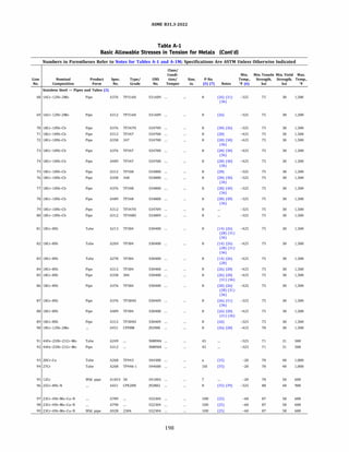
![ASME 831.3-2022
Table A-1
Basic Allowable Stresses in Tension for Metals (Cont'd)
Numbers in Parentheses Refer to Notes for Tables A-1 and A-lM; Specifications Are ASTM Unless Otherwise Indicated
Min.
Line Temp.
Basic Allowable Stress, S, ksi, at Metal Temperature, °F [Notes (1). (2a)]
No. to 100 200 300 400 500 600 650 700 750 800 850 900 950 1,000 1,050 1,100 1,150 1,200 1,250 1,300 1,350 1,400 1,450 1,500
Stainless Steel - Pipes and Tubes (3) (Cont'd)
68 20.0 20.0 20.0 19.3 18.0 17.0 16.6 16.3 16.1 15.9 15.7 15.6 15.4 15.3 15.1 12.4 9.8 7.4
69 20.0 20.0 20.0 19.3 18.0 17.0 16.6 16.3 16.1 15.9 15.7 15.6 15.4 15.3 15.1 12.4 9.8 7.4
70 20.0 20.0 20.0 20.0 20.0 19.3 19.0 18.7 18.5 18.3 18.2 18.1 18.1 18.1 17.4 14.1 10.5 7.9
71 20.0 20.0 20.0 20.0 20.0 19.3 19.0 18.7 18.5 18.3 18.2 18.1 18.1 18.1 17.4 14.1 10.5 7.9
72 20.0 20.0 20.0 20.0 20.0 19.3 19.0 18.7 18.5 18.3 18.2 18.1 18.1 18.1 17.4 14.1 10.5 7.9
73 20.0 20.0 20.0 20.0 20.0 19.3 19.0 18.7 18.5 18.3 18.2 18.1 18.1 18.1 17.4 14.1 10.5 7.9
74 20.0 20.0 20.0 20.0 20.0 19.3 19.0 18.7 18.5 18.3 18.2 18.1 18.1 18.1 17.4 14.1 10.5 7.9
75 20.0 20.0 20.0 20.0 20.0 19.3 19.0 18.7 18.5 18.3 18.2 18.1 18.1 18.1 17.4 14.1 10.5 7.9
76 20.0 20.0 20.0 20.0 20.0 19.3 19.0 18.7 18.5 18.3 18.2 18.1 18.1 18.1 17.4 14.1 10.5 7.9
77 20.0 20.0 20.0 20.0 20.0 19.3 19.0 18.7 18.5 18.3 18.2 18.1 18.1 18.1 17.4 14.1 10.5 7.9
78 20.0 20.0 20.0 20.0 20.0 19.3 19.0 18.7 18.5 18.3 18.2 18.1 18.1 18.1 17.4 14.1 10.5 7.9
79 20.0 20.0 20.0 20.0 20.0 19.3 19.0 18.7 18.5 18.3 18.2 18.1 18.1 18.1 17.4 14.1 10.5 7.9
80 20.0 20.0 20.0 20.0 20.0 19.3 19.0 18.7 18.5 18.3 18.2 18.1 18.1 18.1 17.4 14.1 10.5 7.9
81 20.0 20.0 20.0 18.6 17.5 16.6 16.2 15.8 15.5 15.2 14.9 14.6 14.3 14.0 12.4 9.8 7.7 6.1
82 20.0 20.0 20.0 18.6 17.5 16.6 16.2 15.8 15.5 15.2 14.9 14.6 14.3 14.0 12.4 9.8 7.7 6.1
83 20.0 20.0 20.0 18.6 17.5 16.6 16.2 15.8 15.5 15.2 14.9 14.6 14.3 14.0 12.4 9.8 7.7 6.1
84 20.0 20.0 20.0 18.6 17.5 16.6 16.2 15.8 15.5 15.2 14.9 14.6 14.3 14.0 12.4 9.8 7.7 6.1
85 20.0 20.0 20.0 18.6 17.5 16.6 16.2 15.8 15.5 15.2 14.9 14.6 14.3 14.0 12.4 9.8 7.7 6.1
86 20.0 20.0 20.0 18.6 17.5 16.6 16.2 15.8 15.5 15.2 14.9 14.6 14.3 14.0 12.4 9.8 7.7 6.1
87 20.0 20.0 20.0 18.6 17.5 16.6 16.2 15.8 15.5 15.2 14.9 14.6 14.3 14.0 12.4 9.8 7.7 6.1
88 20.0 20.0 20.0 18.6 17.5 16.6 16.2 15.8 15.5 15.2 14.9 14.6 14.3 14.0 12.4 9.8 7.7 6.1
89 20.0 20.0 20.0 18.6 17.5 16.6 16.2 15.8 15.5 15.2 14.9 14.6 14.3 14.0 12.4 9.8 7.7 6.1
90 20.0 20.0 18.9 17.0 15.8 15.0 14.7 14.4 14.2 14.1 13.9 13.7 13.4 13.1 11.5 8.9 6.9 5.4
91 20.7 20.7 20.4 18.7 17.1
92 20.7 20.7 20.4 18.7 17.1
93 23.3 23.3 23.3 23.3 23.3 23.3 14.6 12.5 10.7 9.2 7.9 5.9 4.0 2.5
94 23.3 23.3 22.5 21.9 21.5 20.9 20.6 20.2 19.7 19.1 18.4 17.5 16.4 15.1
95 23.3 23.3 23.3 22.8 22.1 21.2
96 26.7 26.7 26.7 26.7 26.7 26.7 26.7 26.7 26.7 26.7 26.7 26.7
97 29.0 27.9 26.1 24.7 22.9 19.2
98 29.0 27.9 26.1 24.7 22.9 19.2
99 29.0 27.9 26.1 24.7 22.9 19.2
199
5.5
5.5
5.9
5.9
5.9
5.9
5.9
5.9
5.9
5.9
5.9
5.9
5.9
4.7
4.7
4.7
4.7
4.7
4.7
4.7
4.7
4.7
4.3
4.1
4.1
4.4
4.4
4.4
4.4
4.4
4.4
4.4
4.4
4.4
4.4
4.4
3.7
3.7
3.7
3.7
3.7
3.7
3.7
3.7
3.7
3.4
3.1
3.1
3.2
3.2
3.2
3.2
3.2
3.2
3.2
3.2
3.2
3.2
3.2
2.9
2.9
2.9
2.9
2.9
2.9
2.9
2.9
2.9
2.8
2.3
2.3
2.5
2.5
2.5
2.5
2.5
2.5
2.5
2.5
2.5
2.5
2.5
2.3
2.3
2.3
2.3
2.3
2.3
2.3
2.3
2.3
2.3
1.7
1.7
1.8
1.8
1.8
1.8
1.8
1.8
1.8
1.8
1.8
1.8
1.8
1.8
1.8
1.8
1.8
1.8
1.8
1.8
1.8
1.8
1.9
1.3
1.3
1.3
1.3
1.3
1.3
1.3
1.3
1.3
1.3
1.3
1.3
1.3
1.4
1.4
1.4
1.4
1.4
1.4
1.4
1.4
1.4
1.6](https://image.slidesharecdn.com/26162943-231229160810-282cb07a/85/ASME-B31-3-2022-Procces-piping-code-for-b31-3-226-320.jpg)
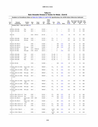
![ASME 831.3-2022
Table A-1
Basic Allowable Stresses in Tension for Metals (Cont'd)
Numbers in Parentheses Refer to Notes for Tables A-1 and A-lM; Specifications Are ASTM Unless Otherwise Indicated
Basic Allowable Stress, S, ksi, at Metal Temperature, °F [Notes (1). (2a)]
Min.
Line Temp.
No. to 100 200 300 400 500 600 650 700 750 800 850 900 950 1,000 1,050 1,100 1,150 1,200 1,250 1,300 1,350 1,400 1,450 1,500
Stainless Steel - Pipes and Tubes (3) (Cont'd)
100 29.3 29.3 28.9 26.7 25.8 24.7 24.3 24.1 23.9 23.8 23.6
101 29.3 29.3 28.9 26.7 25.8 24.7 24.3 24.1 23.9 23.8 23.6
102 30.0
103 30.0 30.0 29.6 27.3 25.8 24.7 24.3 24.1 23.9 23.7 22.8
104 30.0 30.0 29.6 27.3 25.8 24.7 24.3 24.1 23.9 23.7 22.8
105 30.0 30.0 28.9 27.8 27.2 26.9
106 30.0 30.0 28.9 27.8 27.2 26.9
107 30.0 30.0 28.9 27.8 27.2 26.9
108 30.0 27.6 24.7 23.4 23.0 22.9 22.8 22.6 22.3 21.8 21.5
109 30.0 27.6 24.7 23.4 23.0 22.9 22.8 22.6 22.3 21.8 21.5
110 30.0 30.0 29.5 27.3 25.8 24.7 24.3 24.1 23.9 23.7 23.6
111 30.0 30.0 29.5 27.3 25.8 24.7 24.3 24.1 23.9 23.7 23.6
112 30.0 30.0 29.5 27.3 25.8 24.7 24.3 24.1 23.9 23.7 23.6
113 30.0 30.0 29.5 27.3 25.8 24.7 24.3 24.1 23.9 23.7 23.6
114 30.0
115 30.0 30.0 29.9 28.6 27.7 26.2 25.7 25.1 24.7 24.3
116 30.0 30.0 29.9 28.6 27.7 26.2 25.7 25.1 24.7 24.3
117 30.0 30.0 29.9 28.6 27.7 26.2 25.7 25.1 24.7 24.3
118 30.0 30.0 29.9 28.6 27.7 26.2 25.7 25.1 24.7 24.3
119 30.0 30.0 30.0 29.6 27.7 26.2 25.7 25.1 24.7 24.3
120 30.0 30.0 30.0 29.6 27.7 26.2 25.7 25.1 24.7 24.3
121 30.0 30.0 30.0 29.6 27.7 26.2 25.7 25.1 24.7 24.3
122 30.0 30.0 30.0 29.6 27.7 26.2 25.7 25.1 24.7 24.3
123 31.3 31.3 29.8 28.5 28.5 28.5
124 31.3 31.3 29.8 28.5 28.5 28.5
125 31.7 31.7 30.6 29.4 28.7 28.4
126 31.7 31.7 30.6 29.4 28.7 28.4
127 33.7 33.7 32.1 31.0 30.9 30.9
128 33.7 33.7 32.1 31.0 30.9 30.9
129 31.7 30.7 28.9 28.6 28.6 28.6 28.6
130 31.7 30.7 28.9 28.6 28.6 28.6 28.6
201](https://image.slidesharecdn.com/26162943-231229160810-282cb07a/85/ASME-B31-3-2022-Procces-piping-code-for-b31-3-228-320.jpg)
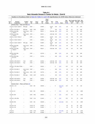
![ASME 831.3-2022
Table A-1
Basic Allowable Stresses in Tension for Metals (Cont'd)
Numbers in Parentheses Refer to Notes for Tables A-1 and A-lM; Specifications Are ASTM Unless Otherwise Indicated
Min.
Line Temp.
Basic Allowable Stress, S, ksi, at Metal Temperature, °F [Notes (1). (2a)]
No. to 100 200 300 400 500 600 650 700 750 800 850 900 950 1,000 1,050 1,100 1,150 1,200 1,250 1,300 1,350 1,400 1,450 1,500
Stainless Steel - Pipes and Tubes (3) (Cont'd)
131 31.7 30.7 28.9 28.6 28.6 28.6 28.6
132 31.7 31.7 30.6 29.4 28.7 28.4
133 32.9 32.9 32.9 32.9 32.9 32.8
134 32.9 32.9 32.9 32.9 32.9 32.8
135 33.3 32.3 30.4 30.1 30.1 30.1 30.1
136 33.3 32.3 30.4 30.1 30.1 30.1 30.1
137 33.3 32.3 30.4 30.1 30.1 30.1 30.1
138 35.8 35.8 35.8 35.8 35.8 35.7
139 35.8 35.8 35.8 35.8 35.8 35.7
140 36.3 35.9 34.4 34.0 34.0 34.0
141 36.3 35.9 34.4 34.0 34.0 34.0
142 36.3 36.3 34.0 33.5 33.0 33.0
143 36.3 36.3 34.0 33.5 33.0 33.0
144 38.3 38.1 35.8 34.5 33.8 33.2 33.1 32.7 32.4 32.0
145 38.7 38.5 36.4 35.1 34.5 34.3
146 38.7 38.5 36.4 35.1 34.5 34.3
147 38.7 38.5 36.4 35.1 34.5 34.3
148 38.7 38.6 36.8 35.6 35.2 35.2
149 38.7 38.6 36.8 35.6 35.2 35.2
Stainless Steel - Plates and Sheets (3)
150 16.7
151 16.7 15.3 14.8 14.5 14.3 14.0 13.8 13.5 13.1 12.6 12.0 11.3 8.4 4.0
152 16.7 16.7 16.7 15.8 14.7 14.0 13.7 13.5 13.3 13.0 12.8 12.6 12.3 12.0 6.3 5.1 4.0 3.2 2.6 2.1 1.7 1.1 1.0 0.9
153 16.7 16.7 16.7 15.7 14.8 14.0 13.7 13.5 13.2 12.9 12.7 12.4 12.1 11.8 10.8 10.2 8.8 6.4 4.7 3.5 2.5 1.8 1.3 1.0
154 20.0 20.0 20.0 18.6 17.5 16.6 16.2 15.8 15.5 15.2 14.9 14.6 14.3 14.0
155 22.0 22.0 22.0 21.5 20.8 20.0
156 23.3 23.3 23.3 22.8 22.1 21.2
157 20.0 18.4 17.8 17.4 17.2 16.8 16.6 16.2 15.7 15.1 14.4 12.3 8.8 6.4 4.4 2.9 1.8 1.0
158 20.0 18.4 17.8 17.4 17.2 16.8 16.6 16.2 15.7 15.1 14.4 12.3 8.8 6.4 4.4 2.9 1.8 1.0
203](https://image.slidesharecdn.com/26162943-231229160810-282cb07a/85/ASME-B31-3-2022-Procces-piping-code-for-b31-3-230-320.jpg)
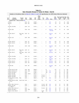
![ASME 831.3-2022
Table A-1
Basic Allowable Stresses in Tension for Metals (Cont'd)
Numbers in Parentheses Refer to Notes for Tables A-1 and A-lM; Specifications Are ASTM Unless Otherwise Indicated
Basic Allowable Stress, S, ksi, at Metal Temperature, °F [Notes (1). (2a)]
Min.
Line Temp.
No. to 100 200 300 400 500 600 650 700 750 800 850 900 950 1,000 1,050 1,100 1,150 1,200 1,250 1,300 1,350 1,400 1,450 1,500
Stainless Steel - Plates and Sheets (3) (Cont'd)
159 20.0 18.4 17.8 17.4 17.2 16.8 16.6 16.2 15.7 15.1 14.4 12.0 9.2 6.5 4.5 3.2 2.4 1.8
160 20.0 18.4 17.8 17.4 17.2 16.8 16.6 16.2 15.7 15.1 14.4 12.0 9.2 6.5 4.5 3.2 2.4 1.8
161 20.0 20.0 20.0 18.9 17.7 16.9 16.5 16.2 15.8 15.5 15.2
162 20.0 20.0 20.0 20.0 19.3 18.5 18.2 17.9 17.7 17.4 17.2 16.9 15.9 9.9 7.1 5.0 3.6 2.5 1.5 0.8 0.5 0.4 0.3 0.2
163 20.0 20.0 20.0 20.0 19.3 18.3 17.8 17.5 17.2 16.9 16.7 16.5 16.4 16.2 9.6 6.9 5.0 3.6 2.6 1.7 1.1 0.8 0.5 0.3
164 20.0 20.0 20.0 20.0 19.4 18.8 18.5 18.2 18.0 17.7 17.5 17.2 16.9 13.8 10.3 7.6 5.5 4.0 3.0 2.2 1.7 1.3 1.0 0.8
165 20.0 20.0 20.0 20.0 20.0 19.3 19.0 18.7 18.5 18.3 18.2 18.1 18.1 16.0 12.1 9.1 6.1 4.4 3.3 2.2 1.5 1.2 0.9 0.8
166 20.0 20.0 20.0 20.0 20.0 19.3 19.0 18.7 18.5 18.3 18.2 18.1 18.1 16.0 12.1 9.1 6.1 4.4 3.3 2.2 1.5 1.2 0.9 0.8
167 20.0 20.0 20.0 20.0 19.3 18.5 18.2 17.9 17.7 17.4 17.2 16.9 16.7 13.8 10.3 7.6 5.5 4.0 3.0 2.2 1.7 1.3 1.0 0.8
168 20.0 20.0 20.0 20.0 19.3 18.3 17.8 17.5 17.2 16.9 16.7 16.5 16.4 16.2 12.3 9.1 6.9 5.4 4.1 3.2 2.5 1.9 1.5 1.1
169 20.0 20.0 20.0 20.0 19.3 18.3 17.8 17.5 17.2 16.9 16.7 16.5 16.4 16.2 12.3 9.1 6.9 5.4 4.1 3.2 2.5 1.9 1.5 1.1
170 20.0 20.0 20.0 19.3 18.0 17.0 16.6 16.3 16.1 15.9 15.7 15.6 15.4 15.3 15.1 12.4 9.8 7.4 5.5 4.1 3.1 2.3 1.7 1.3
171 20.0 20.0 20.0 19.3 18.0 17.0 16.6 16.3 16.1 15.9 15.7 15.6 15.4 15.3 15.1 12.4 9.8 7.4 5.5 4.1 3.1 2.3 1.7 1.3
172 20.0 20.0 20.0 20.0 20.0 19.3 19.0 18.7 18.5 18.3 18.2 18.1 18.1 18.1 17.4 14.1 10.5 7.9 5.9 4.4 3.2 2.5 1.8 1.3
173 20.0 20.0 20.0 20.0 20.0 19.3 19.0 18.7 18.5 18.3 18.2 18.1 18.1 18.1 17.4 14.1 10.5 7.9 5.9 4.4 3.2 2.5 1.8 1.3
174 20.0 20.0 20.0 18.6 17.5 16.6 16.2 15.8 15.5 15.2 14.9 14.6 14.3 14.0 12.4 9.8 7.7 6.1 4.7 3.7 2.9 2.3 1.8 1.4
175 20.7 20.7 20.4 18.7 17.1
176 29.0 27.9 26.1 24.7 22.9 19.2
177 30.0 30.0 28.9 27.8 27.2 26.9
178 30.0 27.6 24.7 23.4 23.0 22.9 22.8 22.6 22.3 21.8 21.5
179 30.0 30.0 29.6 27.4 25.8 24.7 24.3 24.1 23.9 23.7 23.6
180 30.0 30.0 29.6 27.4 25.8 24.7 24.3 24.1 23.9 23.7 23.6
181 30.0 30.0 29.9 28.6 27.7 26.2 25.7 25.1 24.7 24.3
182 30.0 30.0 30.0 29.6 27.7 26.2 25.7 25.1 24.7 24.3
183 31.3 31.3 29.8 28.5 28.5 28.5
184 32.9 32.9 32.9 32.9 32.9 32.8
185 33.7 33.7 32.1 31.0 30.9 30.9
186 31.7 31.7 30.6 29.4 28.7 28.4
187 31.7 30.7 28.9 28.6 28.6 28.6 28.6
205](https://image.slidesharecdn.com/26162943-231229160810-282cb07a/85/ASME-B31-3-2022-Procces-piping-code-for-b31-3-232-320.jpg)
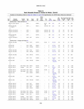
![ASME 831.3-2022
Table A-1
Basic Allowable Stresses in Tension for Metals (Cont'd)
Numbers in Parentheses Refer to Notes for Tables A-1 and A-lM; Specifications Are ASTM Unless Otherwise Indicated
Min.
Line Temp.
Basic Allowable Stress, S, ksi, at Metal Temperature, °F [Notes (1). (2a)]
No. to 100 200 300 400 500 600 650 700 750 800 850 900 950 1,000 1,050 1,100 1,150 1,200 1,250 1,300 1,350 1,400 1,450 1,500
188 33.3 32.3 30.4 30.1 30.1 30.1 30.1
189 35.8 35.8 35.8 35.8 35.8 35.7
190 36.3 36.3 34.5 33.5 33.0 33.0
191 38.7 38.6 36.8 35.6 35.2 35.2
192 36.3 36.3 34.8 34.0 33.9 33.9
193 38.7 38.5 36.4 35.1 34.5 34.3
194 16.7 16.7 16.7 15.7 14.8 14.0 13.7 13.5 13.2 12.9 12.7
195 16.7
196 16.7
16.7 16.7 15.8 14.7 14.0 13.7 13.5 13.3 13.0 12.8 12.6 12.3 12.0 6.3 5.1
16.7 16.7 15.8 14.7 14.0 13.7 13.5 13.3 13.0 12.8 12.6 12.3 12.0 6.3 5.1
197 16.7
198 16.7
16.7 16.7 15.7 14.8 14.0 13.7 13.5 13.2 12.9 12.7 12.4 12.1 11.8 10.8 10.2
16.7 16.7 15.7 14.8 14.0 13.7 13.5 13.2 12.9 12.7 12.4 12.1 11.8 10.8 10.2
199 20.0 20.0 20.0 18.9 17.7 16.9 16.5 16.2 15.8 15.5 15.2
200 20.0 20.0 20.0 20.0 19.3 18.5 18.2 17.9 17.7 17.4 17.2 16.9 15.9 9.9 7.1
201 20.0 20.0 20.0 20.0 19.3 18.5 18.2 17.9 17.7 17.4 17.2 16.9 15.9 9.9 7.1
202 16.7 16.7 16.7 16.7 16.1 15.2 14.9 14.6 14.3 14.1 13.9 13.8 13.6 13.5 9.6
203 20.0 20.0 20.0 20.0 19.3 18.3 17.8 17.5 17.2 16.9 16.7 16.5 16.4 16.2 9.6
204 20.0 20.0 20.0 20.0 19.3 18.3 17.8 17.5 17.2 16.9 16.7 16.5 16.4 16.2 9.6
205 20.0 20.0 20.0 20.0 19.3 18.3 17.8 17.5 17.2 16.9 16.7 16.5 16.4 16.2 9.6
206 20.0 20.0 20.0 20.0 19.4 18.8 18.5 18.2 18.0 17.7 17.5 17.2 16.9 13.8 10.3
207 20.0 20.0 20.0 20.0 19.3 18.5 18.2 17.9 17.7 17.4 17.2 16.9 16.7 13.8 10.3
208 20.0 20.0 20.0 20.0 19.3 18.5 18.2 17.9 17.7 17.4 17.2 16.9 16.7 13.8 10.3
209 20.0 20.0 20.0 20.0 20.0 19.3 19.0 18.7 18.5 18.3 18.2 18.1 18.1 16.0 12.1
210 20.0 20.0 20.0 20.0 20.0 19.3 19.0 18.7 18.5 18.3 18.2 18.1 18.1 16.0 12.1
211 20.0 20.0 20.0 20.0 20.0 19.3 19.0 18.7 18.5 18.3 18.2 18.1 18.1 16.0 12.1
212 20.0 20.0 20.0 20.0 20.0 19.3 19.0 18.7 18.5 18.3 18.2 18.1 18.1 16.0 12.1
213 16.7
214 16.7
215 20.0
216 20.0
217 20.0
218 20.0
16.7 16.7 16.7 16.1 15.2 14.9 14.6 14.3 14.1 13.9 13.8 13.6 13.5 12.3
16.7 16.7 16.7 16.1 15.2 14.9 14.6 14.3 14.1 13.9 13.8 13.6 13.5 12.3
20.0 20.0 20.0 19.3 18.3 17.8 17.5 17.2 16.9 16.7 16.5 16.4 16.2 12.3
20.0 20.0 20.0 19.3 18.3 17.8 17.5 17.2 16.9 16.7 16.5 16.4 16.2 12.3
20.0 20.0 20.0 19.3 18.3 17.8 17.5 17.2 16.9 16.7 16.5 16.4 16.2 12.3
20.0 20.0 20.0 19.3 18.3 17.8 17.5 17.2 16.9 16.7 16.5 16.4 16.2 12.3
207
5.0
5.0
6.9
6.9
6.9
6.9
7.6
7.6
7.6
9.1
9.1
9.1
9.1
9.1
9.1
9.1
9.1
9.1
9.1
Stainless Steel - Plates and Sheets (3) (Cont'd)
4.0 3.2
4.0 3.2
8.8 6.4
8.8 6.4
3.6 2.5
3.6 2.5
5.0 3.6
5.0 3.6
5.0 3.6
5.0 3.6
5.5 4.0
5.5 4.0
5.5 4.0
6.1 4.4
6.1 4.4
6.1 4.4
6.1 4.4
6.9
6.9
6.9
6.9
6.9
6.9
5.4
5.4
5.4
5.4
5.4
5.4
Stainless Steel - Forgings and Fittings (3)
2.6
2.6
4.7
4.7
1.5
1.5
2.6
2.6
2.6
2.6
3.0
3.0
3.0
3.3
3.3
3.3
3.3
4.1
4.1
4.1
4.1
4.1
4.1
2.1
2.1
3.5
3.5
0.8
0.8
1.7
1.7
1.7
1.7
2.2
2.2
2.2
2.2
2.2
2.2
2.2
3.2
3.2
3.2
3.2
3.2
3.2
1.7
1.7
2.5
2.5
0.5
0.5
1.1
1.1
1.1
1.1
1.7
1.7
1.7
1.5
1.5
1.5
1.5
2.5
2.5
2.5
2.5
2.5
2.5
1.1
1.1
1.8
1.8
0.4
0.4
0.8
0.8
0.8
0.8
1.3
1.3
1.3
1.2
1.2
1.2
1.2
1.9
1.9
1.9
1.9
1.9
1.9
1.0
1.0
1.3
1.3
0.3
0.3
0.5
0.5
0.5
0.5
1.0
1.0
1.0
0.9
0.9
0.9
0.9
1.5
1.5
1.5
1.5
1.5
1.5
0.9
0.9
1.0
1.0
0.2
0.2
0.3
0.3
0.3
0.3
0.8
0.8
0.8
0.8
0.8
0.8
0.8
1.1
1.1
1.1
1.1
1.1
1.1](https://image.slidesharecdn.com/26162943-231229160810-282cb07a/85/ASME-B31-3-2022-Procces-piping-code-for-b31-3-234-320.jpg)
![ASME 831.3-2022
Table A-1
Basic Allowable Stresses in Tension for Metals (Cont'd)
Numbers in Parentheses Refer to Notes for Tables A-1 and A-lM; Specifications Are ASTM Unless Otherwise Indicated
Min.
Line Temp.
Basic Allowable Stress, S, ksi, at Metal Temperature, °F [Notes (1). (2a)]
No. to 100 200 300 400 500 600 650 700 750 800 850 900 950 1,000 1,050 1,100 1,150 1,200 1,250 1,300 1,350 1,400 1,450 1,500
Stainless Steel - Forgings and Fittings (3) (Cont'd)
219 20.0
220 20.0
221 20.0
222 20.0
223 20.0
224 20.0
225 20.0
226 20.0
227 20.0
228 20.0
229 20.0
230 20.0
231 20.0
232 20.0
233 20.0
234 20.0
235 20.0
236 20.0
20.0 20.0 20.0 19.3 18.3 17.8 17.5 17.2 16.9 16.7 16.5 16.4 16.2 12.3 9.1 6.9
20.0 20.0 20.0 19.3 18.3 17.8 17.5 17.2 16.9 16.7 16.5 16.4 16.2 12.3 9.1 6.9
20.0 20.0 19.3 18.0 17.0 16.6 16.3 16.1 15.9 15.7 15.6 15.4 15.3 15.1 12.4 9.8
20.0 20.0 19.3 18.0 17.0 16.6 16.3 16.1 15.9 15.7 15.6 15.4 15.3 15.1 12.4 9.8
20.0 20.0 20.0 20.0 19.3 19.0 18.7 18.5 18.3 18.2 18.1 18.1 18.1 17.4 14.1 10.5
20.0 20.0 20.0 20.0 19.3 19.0 18.7 18.5 18.3 18.2 18.1 18.1 18.1 17.4 14.1 10.5
20.0 20.0 20.0 20.0 19.3 19.0 18.7 18.5 18.3 18.2 18.1 18.1 18.1 17.4 14.1 10.5
20.0 20.0 20.0 20.0 19.3 19.0 18.7 18.5 18.3 18.2 18.1 18.1 18.1 17.4 14.1 10.5
20.0 20.0 20.0 20.0 19.3 19.0 18.7 18.5 18.3 18.2 18.1 18.1 18.1 17.4 14.1 10.5
20.0 20.0 20.0 20.0 19.3 19.0 18.7 18.5 18.3 18.2 18.1 18.1 18.1 17.4 14.1 10.5
20.0 20.0 20.0 20.0 19.3 19.0 18.7 18.5 18.3 18.2 18.1 18.1 18.1 17.4 14.1 10.5
20.0 20.0 19.3 18.0 17.0 16.6 16.3 16.1 15.9 15.7 15.6 15.4 15.3 15.1 12.4 9.8
20.0 20.0 19.3 18.0 17.0 16.6 16.3 16.1 15.9 15.7 15.6 15.4 15.3 15.1 12.4 9.8
20.0 20.0 19.3 18.0 17.0 16.6 16.3 16.1 15.9 15.7 15.6 15.4 15.3 15.1 12.4 9.8
20.0 20.0 18.6 17.5 16.6 16.2 15.8 15.5 15.2 14.9 14.6 14.3 14.0 12.4 9.8 7.7
20.0 20.0 18.6 17.5 16.6 16.2 15.8 15.5 15.2 14.9 14.6 14.3 14.0 12.4 9.8 7.7
20.0 20.0 18.6 17.5 16.6 16.2 15.8 15.5 15.2 14.9 14.6 14.3 14.0 12.4 9.8 7.7
20.0 20.0 18.6 17.5 16.6 16.2 15.8 15.5 15.2 14.9 14.6 14.3 14.0 12.4 9.8 7.7
237 20.7 20.7 20.4 18.7 17.1 ...
238 23.3 23.3 22.9 22.5 22.1 21.6 21.2 20.6 20.0 19.2 17.2 12.3 8.8 6.4
5.4
5.4
7.4
7.4
7.9
7.9
7.9
7.9
7.9
7.9
7.9
7.4
7.4
7.4
6.1
6.1
6.1
6.1
239 28.3 28.3 27.8 27.3 26.9 26.2 25.7 25.1 24.3 23.3 17.2 12.3 8.8 6.4 4.4 2.9 1.8 1.0
240 29.3
241 29.3
242 29.0
243 30.0
244 30.0
245 30.0
246 30.0
247 31.3
248 31.7
249 31.7
29.3 28.9 26.7 25.2 24.1 23.8 23.6 23.4 23.2 23.0
29.3 28.9 26.7 25.2 24.1 23.8 23.6 23.4 23.2 23.0 ...
27.9 26.1 24.7 22.9 19.2
30.0 28.9 27.8 27.2 26.9
30.0 28.9 27.8 27.2 26.9
30.0 29.9 28.6 27.7 26.2 25.7 25.1 24.7 24.3 ...
30.0 29.9 28.6 27.7 26.2 25.7 25.1 24.7 24.3
31.3 29.8 28.5 28.5 28.5
31.7 30.6 29.4 28.7 28.4
31.7 30.6 29.4 28.7 28.4
209
4.1
4.1
5.5
5.5
5.9
5.9
5.9
5.9
5.9
5.9
5.9
5.5
5.5
5.5
4.7
4.7
4.7
4.7
3.2
3.2
4.1
4.1
4.4
4.4
4.4
4.4
4.4
4.4
4.4
4.1
4.1
4.1
3.7
3.7
3.7
3.7
2.5
2.5
3.1
3.1
3.2
3.2
3.2
3.2
3.2
3.2
3.2
3.1
3.1
3.1
2.9
2.9
2.9
2.9
1.9
1.9
2.3
2.3
2.5
2.5
2.5
2.5
2.5
2.5
2.5
2.3
2.3
2.3
2.3
2.3
2.3
2.3
1.5
1.5
1.7
1.7
1.8
1.8
1.8
1.8
1.8
1.8
1.8
1.7
1.7
1.7
1.8
1.8
1.8
1.8
1.1
1.1
1.3
1.3
1.3
1.3
1.3
1.3
1.3
1.3
1.3
1.3
1.3
1.3
1.4
1.4
1.4
1.4](https://image.slidesharecdn.com/26162943-231229160810-282cb07a/85/ASME-B31-3-2022-Procces-piping-code-for-b31-3-236-320.jpg)
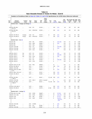
![ASME 831.3-2022
Table A-1
Basic Allowable Stresses in Tension for Metals (Cont'd)
Numbers in Parentheses Refer to Notes for Tables A-1 and A-lM; Specifications Are ASTM Unless Otherwise Indicated
Basic Allowable Stress, S, ksi, at Metal Temperature, °F [Notes (1). (2a)]
Min.
Line Temp.
No. to 100 200 300 400 500 600 650 700 750 800 850
250 36.3 36.3 34.8 34.0 33.9 33.9
251 36.3 36.3 34.8 34.0 33.9 33.9
252 38.7 38.5 36.4 35.1 34.5 34.3
253 38.7 38.5 36.4 35.1 34.5 34.3
254 20.0 20.0 20.0 18.6 17.5 16.6 16.2 15.8 15.5 15.2 14.9
255 20.0 20.0 20.0 18.7 17.5 16.4 16.2 16.0 15.6 15.2 14.9
256 16.7 16.7 16.7 15.8 14.8 14.0 13.7 13.5 13.3 13.0 12.8
257 20.0 20.0 20.0 19.3 17.9 17.0 16.7 16.3 16.1 15.9 15.7
258 20.0 20.0 20.0 19.3 17.9 17.0 16.7 16.3 16.1 15.9 15.7
259 16.7 16.7 16.7 15.5 14.4 13.5 13.2 12.9 12.6 12.4 12.1
260 20.0 20.0 20.0 20.0 19.3 18.3 17.8 17.5 17.2 16.9 16.7
261 20.0 20.0 20.0 20.0 19.3 18.3 17.8 17.5 17.2 16.9 16.7
262 20.0 20.0 20.0 20.0 19.3 18.3 17.8 17.5 17.2 16.9 16.7
263 20.0 20.0 20.0 20.0 20.0 19.3 19.0 18.7 18.5 18.3 18.2
264 20.0 20.0 20.0 20.0 20.0 19.3 19.0 18.7 18.5 18.3 18.2
265 20.0 20.0 20.0 20.0 20.0 19.3 19.0 18.7 18.5 18.3 18.2
266 20.7 20.7 20.4 18.7 17.1
267 30.0 30.0 28.9 27.8 27.2 26.9
268 30.0 30.0 29.5 27.3 25.8 24.7 24.3 24.1 23.9 23.7 23.6
269 30.0
270 31.3
271 31.7
272 32.9
273 33.3
274 35.8
275 36.3
276 38.7
277 16.7
278 18.7
279 18.7
280 18.7
281 20.0
30.0 29.9 28.6
31.3 29.8 28.5
31.7 30.6 29.4
32.9 32.9 32.9
33.1 31.4 30.4
35.8 35.8 35.8
36.3 34.5 33.5
38.5 36.4 35.1
18.7 18.5 18.0
18.7 18.5 18.0
27.7 26.2 25.7 25.1 24.7 24.3
28.5 28.5
28.7 28.4
32.9 32.8
29.7 29.2 29.0 28.8 28.6 28.3
35.8 35.7
33.0 33.0
34.5 34.3
17.7 17.1 16.7 16.3 15.9 15.4
17.7 17.1 16.7 16.3 15.9 15.4
282 20.0 20.0 20.0 18.6 17.5 16.6 16.2 15.8 15.5 15.2
27.9
14.9
14.9
283 20.0 20.0 20.0 19.2 17.9 17.0 16.6 16.3 16.0 15.8 15.7
900 950 1,000 1,050 1,100 1,150 1,200 1,250 1,300 1,350 1,400 1,450 1,500
Stainless Steel - Forgings and Fittings (3) (Cont'd)
Stainless Steel - Bar (3)
14.6 14.3 14.0 12.4 9.8 7.7 6.1 4.7 3.7 2.9 2.3 1.8 1.4
14.6 14.4 13.8 12.2 9.7 7.7 6.0 4.7 3.7 2.9 2.3 1.8 1.4
11.9 9.9 7.8 6.3 5.1 4.0 3.2 2.6 2.1 1.7 1.1 1.0 0.9
15.5 15.4 15.3 14.5 12.4 9.8 7.4 5.5 4.1 3.1 2.3 1.7 1.3
15.5 15.4 15.3 14.5 12.4 9.8 7.4 5.5 4.1 3.1 2.3 1.7 1.3
11.8 11.5 11.2 10.8 10.2 8.8 6.4 4.7 3.5 2.5 1.8 1.3 1.0
16.5 16.4 16.2 9.6 6.9 5.0 3.6 2.6 1.7 1.1 0.8 0.5 0.3
16.5 16.4 16.2 12.3 9.1 6.9 5.4 4.1 3.2 2.5 1.9 1.5 1.1
16.5 16.4 16.2 12.3 9.1 6.9 5.4 4.1 3.2 2.5 1.9 1.5 1.1
18.1 18.1 16.0 12.1 9.1 6.1 4.4 3.3 2.2 1.5 1.2 0.9 0.8
18.1 18.1 18.1 17.4 14.1 10.5 7.9 5.9 4.4 3.2 2.5 1.8 1.3
18.1 18.1 18.1 17.4 14.1 10.5 7.9 5.9 4.4 3.2 2.5 1.8 1.3
27.5 27.0 26.3 25.5 20.4 13.0 8.3
Stainless Steel - Castings (3)
14.4 13.9 11.1 8.5 6.5 5.0 3.8 2.9 2.3 1.8 1.3 0.9 0.8
14.4 13.9 11.3 9.8 8.5 7.3 6.0 4.8 3.5 2.4 1.6 1.1 0.8
211](https://image.slidesharecdn.com/26162943-231229160810-282cb07a/85/ASME-B31-3-2022-Procces-piping-code-for-b31-3-238-320.jpg)
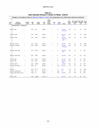
![ASME 831.3-2022
Table A-1
Basic Allowable Stresses in Tension for Metals (Cont'd)
Numbers in Parentheses Refer to Notes for Tables A-1 and A-lM; Specifications Are ASTM Unless Otherwise Indicated
Min.
Line Temp.
Basic Allowable Stress, S, ksi, at Metal Temperature, °F [Notes (1). (2a)]
No. to 100 200 300 400 500 600 650 700 750 800 850 900 950 1,000 1,050 1,100 1,150 1,200 1,250 1,300 1,350 1,400 1,450 1,500
284 20.0 20.0 20.0 18.6 17.5 16.6 16.2 15.8 15.5 15.2 14.9 14.6 14.3 12.2
285 20.0 20.0 19.9 19.4 18.9 18.3 17.9 17.5 17.0 16.5 15.9 15.4 14.3 11.1
286 20.0 20.0 19.9 19.4 18.9 18.3 17.9 17.5 17.0 16.5 15.9 15.4 14.3 11.1
287 20.0 20.0 20.0 19.5 18.8 18.4 18.3 18.3 18.2 18.2 18.1 18.0 18.0 16.0
288 20.0 20.0 20.0 18.6 17.5 16.6 16.2 15.8 15.5 15.2 14.9 14.6 14.3 14.0
289 20.7
290 21.7
291 23.3 23.3 22.7 21.7 20.4 19.3 18.9 18.5
292 23.3 23.3 22.7 21.7 20.4 19.3 18.9 18.5
293 26.7 26.7 26.7 26.7 26.7 26.7 26.7 26.7 26.7 26.7 26.7 26.7
294 30.0 30.0 28.7 28.4 28.2
295 30.0 30.0 29.4 28.9 28.4 27.7 27.2 26.5 17.5 16.8 14.9 11.0 7.6 5.0
296 31.7 31.6 29.3 28.2 28.2 28.2
297 33.3 33.2 31.4 30.3 29.8 29.6
298 36.7 36.7 35.9 35.3 34.8 33.9 33.3 32.4
213
9.5 7.5
8.5 6.5
8.5 6.5
12.1 9.1
12.1 9.1
3.3 2.3
6.0 4.8
5.0 3.8
5.0 3.8
6.1 4.4
6.1 4.4
1.5 1.0
Stainless Steel - Castings (3) (Cont'd)
3.9 3.3 2.7 2.3 2.0 1.7
2.9 2.3 1.8 1.3 0.9 0.8
2.9 2.3 1.8 1.3 0.9 0.8
3.3 2.2 1.5 1.2 0.9 0.8
3.3 2.2 1.5 1.2 0.9 0.8](https://image.slidesharecdn.com/26162943-231229160810-282cb07a/85/ASME-B31-3-2022-Procces-piping-code-for-b31-3-240-320.jpg)
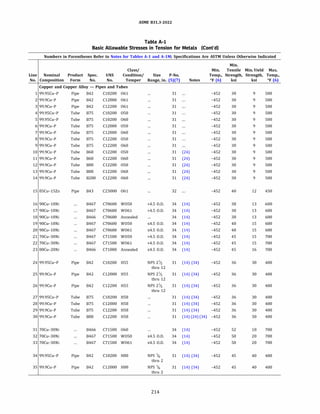
![ASME 831.3-2022
Table A-1
Basic Allowable Stresses in Tension for Metals (Cont'd)
Numbers in Parentheses Refer to Notes for Tables A-1 and A-lM; Specifications Are ASTM Unless Otherwise Indicated
Basic Allowable Stress, S, ksi, at Metal Temperature, °F [Notes (1), (2a)]
Min.
Line Temp.
No. to 100 150 200 250 300 350 400 450 500 550 600 650 700
Copper and Copper Alloy - Pipes and Tubes
1 6.0 5.1 4.9 4.8 4.7 4.0 3.0 2.3 1.7
2 6.0 5.1 4.9 4.8 4.7 4.0 3.0 2.3 1.7
3 6.0 5.1 4.9 4.8 4.7 4.0 3.0 2.3 1.7
4 6.0 5.1 4.9 4.8 4.7 4.0 3.0 2.3 1.7
5 6.0 5.1 4.9 4.8 4.7 4.0 3.0 2.3 1.7
6 6.0 5.1 4.9 4.8 4.7 4.0 3.0 2.3 1.7
7 6.0 5.1 4.9 4.8 4.7 4.0 3.0 2.3 1.7
8 6.0 5.1 4.9 4.8 4.7 4.0 3.0 2.3 1.7
9 6.0 5.1 4.9 4.8 4.7 4.0 3.0 2.3 1.7
10 6.0 5.1 4.9 4.8 4.7 4.0 3.0 2.3 1.7
11 6.0 5.1 4.9 4.8 4.7 4.0 3.0 2.3 1.7
12 6.0 5.1 4.9 4.8 4.7 4.0 3.0 2.3 1.7
13 6.0 5.1 4.9 4.8 4.7 4.0 3.0 2.3 1.7
14 6.0 5.1 4.9 4.8 4.7 4.0 3.0 2.3 1.7
15 8.0 7.9 7.9 7.9 7.9 7.0 5.0 2.0
16 8.7 8.4 8.2 8.0 7.8 7.7 7.5 7.4 7.3 7.0 6.0
17 8.7 8.4 8.2 8.0 7.8 7.7 7.5 7.4 7.3 7.0 6.0
18 8.7 8.4 8.2 8.0 7.8 7.7 7.5 7.4 7.3 7.0 6.0
19 10.0 9.7 9.5 9.3 9.1 8.9 8.7 8.5 8.0 7.0 6.0
20 10.0 9.7 9.5 9.3 9.1 8.9 8.7 8.5 8.0 7.0 6.0
21 10.0 9.6 9.4 9.2 9.0 8.8 8.6 8.4 8.2 8.1 8.0 7.9 7.8
22 10.0 9.6 9.4 9.2 9.0 8.8 8.6 8.4 8.2 8.1 8.0 7.9 7.8
23 10.7 10.6 10.5 10.4 10.2 10.1 9.9 9.6 9.3 8.9 8.4 7.7 7.0
24 12.0 11.6 10.9 10.4 10.0 9.8 9.5
25 12.0 11.6 10.9 10.4 10.0 9.8 9.5
26 12.0 11.6 10.9 10.4 10.0 9.8 9.5
27 12.0 11.6 10.9 10.4 10.0 9.8 9.5
28 12.0 11.6 10.9 10.4 10.0 9.8 9.5
29 12.0 11.6 10.9 10.4 10.0 9.8 9.5
30 12.0 11.6 10.9 10.4 10.0 9.8 9.5
31 12.0 11.6 11.3 11.0 10.8 10.6 10.3 10.1 9.9 9.8 9.6 9.5 9.4
32 13.3 12.9 12.6 12.3 12.0 11.7 11.5 11.2 11.0 10.8 10.7 10.5 10.4
33 13.3 12.9 12.6 12.3 12.0 11.7 11.5 11.2 11.0 10.8 10.7 10.5 10.4
34 15.0 14.5 13.6 13.0 12.6 12.2 4.3
35 15.0 14.5 13.6 13.0 12.6 12.2 4.3
215](https://image.slidesharecdn.com/26162943-231229160810-282cb07a/85/ASME-B31-3-2022-Procces-piping-code-for-b31-3-242-320.jpg)
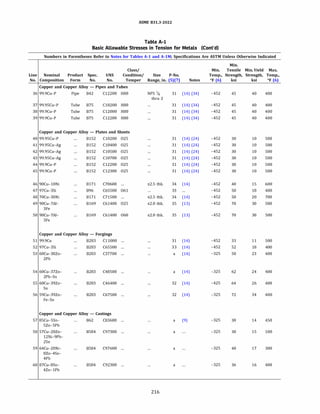
![ASME 831.3-2022
Table A-1
Basic Allowable Stresses in Tension for Metals (Cont'd)
Numbers in Parentheses Refer to Notes for Tables A-1 and A-lM; Specifications Are ASTM Unless Otherwise Indicated
Basic Allowable Stress, S, ksi, at Metal Temperature, °F [Notes (1), (2a)]
Min.
Line Temp.
No. to 100 150 200 250 300 350 400 450 500 550 600 650 700
Copper and Copper Alloy - Pipes and Tubes (Cont'd)
36 15.0 14.5 13.6 13.0 12.6 12.2 4.3
37 15.0 14.5 13.6 13.0 12.6 12.2 4.3
38 15.0 14.5 13.6 13.0 12.6 12.2 4.3
39 15.0 14.5 13.6 13.0 12.6 12.2 4.3
Copper and Copper Alloy - Plates and Sheets
40 6.7 5.7 5.4 5.3 5.0 4.0 3.0 2.3 1.7
41 6.7 5.7 5.4 5.3 5.0 4.0 3.0 2.3 1.7
42 6.7 5.7 5.4 5.3 5.0 4.0 3.0 2.3 1.7
43 6.7 5.7 5.4 5.3 5.0 4.0 3.0 2.3 1.7
44 6.7 5.7 5.4 5.3 5.0 4.0 3.0 2.3 1.7
45 6.7 5.7 5.4 5.3 5.0 4.0 3.0 2.3 1.7
46 10.0 9.7 9.5 9.3 9.1 8.9 8.7 8.5 8.0 7.0 6.0
47 12.0 12.0 11.9 11.9 11.9 10.7 6.8
48 13.3 12.9 12.6 12.3 12.0 11.7 11.5 11.2 11.0 10.8 10.7 10.5 10.4
49 20.0 19.9 19.8 19.7 19.5 19.4 19.2 19.0 18.8
50 20.0 19.9 19.8 19.7 19.5 19.4 19.2 19.0 18.8
Copper and Copper Alloy - Forgings
51 7.3 6.2 6.0 5.8 5.0 4.0 3.0 2.3 1.7
52 12.0 12.0 11.9 11.9 11.9 10.7 6.8
53 15.3 14.5 13.9 13.3 10.5 7.5 2.0
54 16.0 16.0 16.0 16.0 16.0 16.0 16.0
55 17.3 17.3 17.3 17.3 17.1 6.3 2.5
56 22.7 22.7 22.7 22.7 22.7 22.7 22.7
Copper and Copper Alloy - Castings
57 9.3 9.3 9.2 8.6 8.1 7.7 7.4 7.3
58 10.0
59 11.3 10.1 9.5 9.1 8.7
60 10.7 10.7 10.7 10.7 10.7 10.7 10.7
217](https://image.slidesharecdn.com/26162943-231229160810-282cb07a/85/ASME-B31-3-2022-Procces-piping-code-for-b31-3-244-320.jpg)
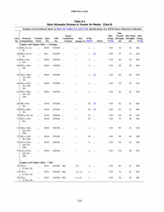
![ASME 831.3-2022
Table A-1
Basic Allowable Stresses in Tension for Metals (Cont'd)
Numbers in Parentheses Refer to Notes for Tables A-1 and A-lM; Specifications Are ASTM Unless Otherwise Indicated
Min.
Line Temp.
No. to 100
61 10.7
62 10.7
63 12.0
64 12.0
65 13.3
66 14.7
67 16.7
68 16.7
69 16.7
70 18.7
71 20.0
72 21.3
73 26.7
74 30.0
75 36.7
76 28.3
77 23.3
78 20.0
150
9.6
9.6
12.0
12.0
13.3
14.7
16.7
15.7
16.7
19.0
21.3
26.7
30.0
36.7
25.9
20.2
17.3
Basic Allowable Stress, S, ksi, at Metal Temperature, °F [Notes (1), (2a)]
200
9.5
9.5
12.0
12.0
13.3
14.7
16.7
15.2
16.7
18.7
21.3
26.7
30.0
36.7
25.4
19.8
17.0
250 300
9.4 9.2
9.4 9.2
12.0 12.0
12.0 12.0
13.3 13.3
14.7 14.7
16.7 16.7
14.8 14.5
16.7 16.7
18.5 18.5
21.3 21.3
26.7 26.7
30.0 30.0
36.7 36.7
25.4 25.4
19.8 19.8
17.0 17.0
350 400
8.9 8.6
8.9 8.6
12.0 12.0
12.0 12.0
13.3
14.7
16.7
14.3 14.2
16.7 16.7
18.5 18.5
21.3
26.7 26.7
30.0
36.7
219
450 500 550 600 650 700
Copper and Copper Alloy - Castings (Cont'd)
8.4 8.3 8.3
14.1 14.1 11.7 7.4
16.7 16.7 16.7 16.7
16.0 13.9
26.7 26.7
Copper and Copper Alloy - Rod](https://image.slidesharecdn.com/26162943-231229160810-282cb07a/85/ASME-B31-3-2022-Procces-piping-code-for-b31-3-246-320.jpg)
![ASME 831.3-2022
Table A-1
Basic Allowable Stresses in Tension for Metals (Cont'd)
Numbers in Parentheses Refer to Notes for Tables A-1 and A-lM; Specifications Are ASTM Unless Otherwise Indicated
Line.
No
Nominal
Composition
Product Spec. Type/
Form No. Grade
Nickel and Nickel Alloy - Pipes and Tubes
99.0Ni-Low C
99.0Ni-Low C
99.0Ni
4 99.0Ni
5 99.0Ni-Low C
6 99.0Ni-Low C
7 99.0Ni
8 99.0Ni
9 67Ni-30Cu
10 67Ni-30Cu
11 33Ni-42Fe-21Cr
12 72Ni-15Cr-8Fe
13 33Ni-42Fe-21Cr
14 33Ni-42Fe-21Cr
15 33Ni-42Fe-21Cr-AI-Ti
16 67Ni-30Cu
17 67Ni-30Cu
18 26Ni-22Cr-5Mo-Ti
19 26Ni-22Cr-5Mo-Ti
20 99.0Ni-Low C
21 99.0Ni-Low C
22 33Ni-42Fe-21Cr
23 72Ni-15Cr-8Fe
24 72Ni-15Cr-8Fe
25 33Ni-42Fe-21Cr
26 31Ni-31Fe-29Cr-Mo
27 99.0Ni
28 99.0Ni
29 35Ni-35Fe-20Cr-Cb
30 35Ni-35Fe-20Cr-Cb
31 35Ni-35Fe-20Cr-Cb
32 42Ni-21.5Cr-3Mo-2.3Cu
33 42Ni-21.5Cr-3Mo-2.3Cu
34 42Ni-21.5Cr-3Mo-2.3Cu
35 42Ni-21.5Cr-3Mo-2.3Cu
36 42Ni-21.5Cr-3Mo-2.3Cu
37 47Ni-22Cr-19Fe-6Mo
38 47Ni-22Cr-19Fe-6Mo
39 40Ni-29Cr-15Fe-5Mo
40 40Ni-29Cr-15Fe-5Mo
8161
8725
8161
8725
8161
8725
8161
8725
8165
8725
8407
8167
8407
8514
8407
8165
8725
8619
8622
8161
8725
8514
8167
8167
8407
8668
8161
8725
8464
8474
8729
8163
8423
8474
8704
8705
8619
8622
8619
8622
UNS
No.
Class/
Condition/
Temper
N02201 Annealed
N02201 Annealed
N02200 Annealed
N02200 Annealed
N02201 Annealed
N02201 Annealed
N02200 Annealed
N02200 Annealed
N04400 Annealed
N04400 Annealed
N08800 H.F. or H.F.
ann.
Size
Range,
in.
p.
No.
(5)
(7)
>5 O.D. 41
>5 O.D. 41
>S O.D. 41
>5 O.D. 41
55 O.D. 41
55 O.D. 41
55 O.D. 41
55 O.D. 41
>5 O.D. 42
>S O.D. 42
45
Notes
N06600 H.F. or H.F. >5 O.D. 43
ann.
N08810 C.D. sol. ann.
or H.F. ann.
N08810 Annealed
N08811 C.D. sol. ann.
or H.F. ann.
N04400 Annealed
N04400 Annealed
N08320 Sol. ann.
N08320 Sol. ann.
N02201 Str. rel.
N02201 Str. rel.
N08800 Annealed
45 (62)
45 (62)
45 (62)
55 O.D. 42
55 O.D. 42
45
45
41
41
45
N06600 H.F. or H.F. 55 O.D. 43
ann.
N06600 C.D. ann.
N08800 C.D. ann.
N08028 Sol. ann.
N02200 Str. rel.
N02200 Str. rel.
N08020 Annealed
N08020 Annealed
N08020 Annealed
N08825 Annealed
N08825 C.D. ann.
N08825 Annealed
N08825 Annealed
N08825 ...
N06007 Sol. ann.
N06007 Sol. ann.
N06030 Sol. ann.
N06030 Sol. ann.
>5 O.D. 43
220
45 (61)
45
41
41
45
45
45
45
45
45
45
45
45
45
45
45
Min.
Temp.,
Of (6)
-325
-325
-325
-325
-325
-325
-325
-325
-325
-325
-325
-325
-325
-325
-325
-325
-325
-325
-325
-325
-325
-325
-325
-325
-325
-325
-325
-325
-325
-325
-325
-325
-325
-325
-325
-325
-325
-325
-325
-325
Minimum Minimum
Tensile Yield Max.
Strength, Strength, Temp.,
ksi ksi °F
so
so
SS
SS
so
so
SS
SS
70
70
65
75
65
65
65
70
70
75
75
60
60
75
80
80
75
73
65
65
80
80
80
85
85
85
85
85
90
90
85
85
10
10
12
12
12
12
15
15
25
25
25
25
25
25
25
28
28
28
28
30
30
30
30
30
30
31
40
40
35
35
35
35
35
35
35
35
35
35
35
35
1,200
1,200
600
600
1,200
1,200
600
600
900
900
1,500
1,200
1,650
1,650
1,650
900
900
800
800
600
600
1,500
1,200
1,200
1,500
850
600
600
800
800
800
1,000
1,000
1,000
1,000
1,000
1,000
800
800
800
Basic Allowable
Stress, S, ksi, at
Metal
Temperature, °F
[Notes (1). (2a)]
Min.
Temp.
to
100
6.7
6.7
8.0
8.0
8.0
8.0
200 300
6.4 6.3
6.4 6.3
8.0 8.0
8.0 8.0
7.7 7.5
7.7 7.5
10.0 10.0 10.0
10.0 10.0 10.0
16.7 14.6 13.6
16.7 14.6 13.6
16.7 16.7 16.7
16.7 16.7 16.7
16.7 16.7 16.7
16.7 16.7 16.7
16.7 16.7 16.7
18.7 16.4 15.2
18.7 16.4 15.2
18.7 18.7 18.7
18.7 18.7 18.7
20.0 20.0 19.8
20.0 20.0 19.8
20.0 20.0 20.0
20.0 20.0 20.0
20.0 20.0 20.0
20.0 20.0 20.0
20.7 20.7 20.7
21.7 21.7 21.6
21.7 21.7 21.6
23.3 23.3 23.3
23.3 23.3 23.3
23.3 23.3 23.3
23.3 23.3 23.3
23.3 23.3 23.3
23.3 23.3 23.3
23.3 23.3 23.3
23.3 23.3 23.3
23.3 23.3 23.3
23.3 23.3 23.3
23.3 23.3 23.3
23.3 23.3 23.3](https://image.slidesharecdn.com/26162943-231229160810-282cb07a/85/ASME-B31-3-2022-Procces-piping-code-for-b31-3-247-320.jpg)
![ASME 831.3-2022
Table A-1
Basic Allowable Stresses in Tension for Metals (Cont'd)
Numbers in Parentheses Refer to Notes for Tables A-1 and A-lM; Specifications Are ASTM Unless Otherwise Indicated
Basic Allowable Stress, S, ksi, at Metal Temperature, 'F [Notes (1), (2a)]
Line
No. 400 500 600 650 700 750 800 850 900 950 1,000 1,050 1,100 1,150 1,200 1,250 1,300 1,350 1,400 1,450 1,500 1,550 1,600 1,650
Nickel and Nickel Alloy - Pipes and Tubes
6.3 6.3 6.3 6.2 6.2 6.1 6.0 5.8 4.5 3.7 3.0 2.4 2.0 1.5 1.2
6.3 6.3 6.3 6.2 6.2 6.1 6.0 5.8 4.5 3.7 3.0 2.4 2.0 1.5 1.2
8.0 8.0 8.0
4 8.0 8.0 8.0
5 7.5 7.5 7.5 7.5 7.4 7.3 7.2 5.8 4.5 3.7 3.0 2.4 2.0 1.5 1.2
6 7.5 7.5 7.5 7.5 7.4 7.3 7.2 5.8 4.5 3.7 3.0 2.4 2.0 1.5 1.2
7 10.0 10.0 10.0
8 10.0 10.0 10.0
9 13.2 13.1 13.1 13.1 13.0 12.9 12.7 11.0 8.0 ...
10 13.2 13.1 13.1 13.1 13.0 12.9 12.7 11.0 8.0
11 16.7 16.7 16.7 16.7 16.7 16.7 16.7 16.7 16.7 16.7 16.6 16.3 13.0 9.8 6.6 4.2 2.0 1.6 1.1 1.0 0.8
12 16.7 16.7 16.7 16.7 16.7 16.7 16.7 16.7 16.0 10.6 7.0 4.5 3.0 2.2 2.0
13 16.7 16.7 16.5 16.1 15.7 15.3 15.0 14.7 14.5 14.2 14.0 13.8 11.6 9.3 7.4 5.9 4.7 3.8 3.0 2.4 1.9 1.4 1.1 0.86
14 16.7 16.7 16.5 16.1 15.7 15.3 15.0 14.7 14.5 14.2 14.0 13.8 11.6 9.3 7.4 5.9 4.7 3.8 3.0 2.4 1.9 1.4 1.1 0.86
15 16.7 16.7 16.5 16.1 15.7 15.3 15.0 14.7 14.5 14.2 14.0 13.8 12.9 10.4 8.3 6.7 5.4 4.3 3.4 2.7 2.2 1.6 1.2 0.91
16 14.7 14.7 14.7 14.7 14.6 14.5 14.3 11.0 8.0
17 14.7 14.7 14.7 14.7 14.6 14.5 14.3 11.0 8.0
18 18.7 18.7 18.6 18.2 17.8 17.5 17.2
19 18.7 18.7 18.6 18.2 17.8 17.5 17.2
20 19.8 19.7 19.0
21 19.8 19.7 19.0
22 20.0 20.0 20.0 20.0 20.0 20.0 20.0 20.0 20.0 20.0 19.9 17.0 13.0 9.8 6.6 4.2 2.0 1.6 1.1 1.0 0.8
23 20.0 20.0 20.0 20.0 20.0 20.0 20.0 20.0 16.0 10.6 7.0 4.5 3.0 2.2 2.0
24 20.0 20.0 20.0 20.0 20.0 20.0 20.0 20.0 16.0 10.6 7.0 4.5 3.0 2.2 2.0
25 20.0 20.0 20.0 20.0 20.0 20.0 20.0 20.0 20.0 20.0 19.9 17.0 13.0 9.8 6.6 4.2 2.0 1.6 1.1 1.0 0.8
26 20.7 20.7 19.5 18.9 18.3 17.7 17.2 16.7 ...
27 21.6 21.4 20.6
28 21.6 21.4 20.6
29 23.3 23.3 23.3 23.3 23.3 23.2 22.7
30 23.3 23.3 23.3 23.3 23.3 23.2 22.7
31 23.3 23.3 23.3 23.3 23.3 23.2 22.7
32 23.3 23.3 23.3 23.3 23.3 23.2 23.0 22.9 22.8 22.6 22.3
33 23.3 23.3 23.3 23.3 23.3 23.2 23.0 22.9 22.8 22.6 22.3
34 23.3 23.3 23.3 23.3 23.3 23.2 23.0 22.9 22.8 22.6 22.3
35 23.3 23.3 23.3 23.3 23.3 23.2 23.0 22.9 22.8 22.6 22.3
36 23.3 23.3 23.3 23.3 23.3 23.2 23.0 22.9 22.8 22.6 22.3
37 23.3 23.3 22.7 22.4 22.2 22.0 21.8 21.7 20.0 19.5 18.9
38 23.3 23.3 22.7 22.4 22.2 22.0 21.8 ...
39 23.2 22.1 21.3 20.9 20.5 20.1 19.7 ...
40 23.2 22.1 21.3 20.9 20.5 20.1 19.7
221](https://image.slidesharecdn.com/26162943-231229160810-282cb07a/85/ASME-B31-3-2022-Procces-piping-code-for-b31-3-248-320.jpg)
![ASME 831.3-2022
Table A-1
Basic Allowable Stresses in Tension for Metals (Cont'd)
Numbers in Parentheses Refer to Notes for Tables A-1 and A-lM; Specifications Are ASTM Unless Otherwise Indicated
Line.
No
Nominal
Composition
Product Spec. Type/
Form No. Grade
Nickel and Nickel Alloy - Pipes and Tubes
41 40Ni-29Cr-15Fe-5Mo
42 72Ni-15Cr-8Fe
43 72Ni-15Cr-8Fe
44 58Ni-29Cr-9Fe
45 58Ni-29Cr-9Fe
46 37Ni-33Fe-25Cr
47 37Ni-33Fe-25Cr
48 37Ni-33Fe-25Cr
49 37Ni-33Fe-25Cr
SO 61Ni-16Mo-16Cr
51 47Ni-22Cr-9Mo-18Fe
52 47Ni-22Cr-9Mo-18Fe
53 31Ni-33Fe-27Cr-6.5Mo
Cu-N
54 31Ni-33Fe-27Cr-6.5Mo
Cu-N
SS 61Ni-16Mo-16Cr
56 54Ni-16Mo-15Cr
57 54Ni-16Mo-15Cr
58 54Ni-16Mo-15Cr
59 67Ni-30Cu
60 67Ni-30Cu
61 46Fe-24Ni-21Cr-6Mo
Cu-N
62 46Fe-24Ni-21Cr-6Mo
Cu-N
63 46Fe-24Ni-21Cr-6Mo
Cu-N
64 46Fe-24Ni-21Cr-6Mo
Cu-N
65 46Fe-24Ni-21Cr-6Mo
Cu-N
66 46Fe-24Ni-21Cr-6Mo-
Cu-N
67 55Ni-21Cr-13.5Mo
68 55Ni-21Cr-13.5Mo
69 58Ni-33Cr-8Mo
70 58Ni-33Cr-8Mo
71 58Ni-33Cr-8Mo
72 59Ni-23Cr-16Mo
73 59Ni-23Cr-16Mo
74 59Ni-23Cr-16Mo
75 59Ni-23Cr-16Mo-1.6Cu
76 59Ni-23Cr-16Mo-1.6Cu
77 59Ni-23Cr-16Mo-1.6Cu
78 62Ni-22Mo-15Cr
8626
8167
8517
8163
8167
8163
8407
8514
8515
8619
8619
8622
8619
8622
8622
8619
8622
8626
8165
8725
8675
8690
8804
8675
8690
8804
8619
8622
8619
8622
8626
8619
8622
8626
8619
8622
8626
8619
UNS
No.
Class/
Condition/
Temper
N06030 Sol. ann.
N06600 C.D. ann.
N06600 C.D. ann.
N06690 C.D. ann.
N06690 C.D. ann.
N08120 Sol. ann.
N08120 Sol. ann.
N08120 Sol. ann.
N08120 Sol. ann.
N06455 Sol. ann.
N06002 Sol. ann.
N06002 Sol. ann.
N08031 Annealed
N08031 Annealed
N06455 Sol. ann.
N10276 Sol. ann.
N10276 Sol. ann.
N10276 Sol. ann.
N04400 Str. rel.
N04400 Str. rel.
N08367 Annealed
N08367 Annealed
N08367 Annealed
N08367 Annealed
N08367 Annealed
N08367 Annealed
N06022 Sol. ann.
N06022 Sol. ann.
N06035 Sol. ann.
N06035 Sol. ann.
N06035 Sol. ann.
N06059 Sol. ann.
N06059 Sol. ann.
N06059 Sol. ann.
N06200 Sol. ann.
N06200 Sol. ann.
N06200 Sol. ann.
N10362 Sol. ann.
Size
Range,
in.
p.
No.
(5)
(7)
45
�S O.D. 43
Notes
43 -325
�3 O.D. 43
�S O.D. 43
>%6
All
All
All
All
All
222
45
45
45
45
43
43
43
45
45
43
43
43
43
42 (54)
42 (54)
45
45
45
45
45
45
43
43
43
43
43
43
43
43
43
43
43
43
Min.
Temp.,
Of (6)
-325
-325
80
-325
-325
-325
-325
-325
-325
-325
-325
-325
-325
-325
-325
-325
-325
-325
-325
-325
-325
-325
-325
-325
-325
-325
-325
-325
-325
-325
-325
-325
-325
-325
-325
-325
-325
-325
Minimum Minimum
Tensile Yield Max.
Strength, Strength, Temp.,
ksi ksi °F
85
80
35
85
85
90
90
90
90
100
100
100
94
94
100
100
100
100
85
85
95
95
95
100
100
100
100
100
85
85
85
100
100
100
100
100
100
105
35 800
35 1,200
1,200 23.3
35
35
40
40
40
40
40
40
40
40
40
40
41
41
41
SS
SS
45
45
45
45
45
45
45
45
35
35
35
45
45
45
45
45
45
45
900
900
1,650
1,650
1,650
1,650
800
1,500
1,500
800
800
800
1,250
1,250
1,250
500
500
900
900
900
900
900
800
800
800
800
800
800
800
800
800
800
800
800
800
Basic Allowable
Stress, S, ksi, at
Metal
Temperature, °F
[Notes (1). (2a)]
Min.
Temp.
to
100 200 300
23.3 23.3 23.3
23.3 23.3 23.3
23.3 23.3 23.3
23.3 23.3 23.3
23.3 23.3 23.3
26.7 26.7 26.7
26.7 26.7 26.7
26.7 26.7 26.7
26.7 26.7 26.7
26.7 26.7 26.7
26.7 26.7 26.7
26.7 26.7 26.7
26.7 26.7 26.7
26.7 26.7 26.7
26.7 26.7 26.7
27.3 27.3 27.3
27.3 27.3 27.3
27.3 27.3 27.3
28.3 28.3 28.3
28.3 28.3 28.3
30.0 30.0 29.9
30.0 30.0 29.9
30.0 30.0 29.9
30.0 30.0 30.0
30.0 30.0 30.0
30.0 30.0 29.9
30.0 30.0 30.0
30.0 30.0 30.0
23.3 23.3 23.3
23.3 23.3 23.3
23.3 23.3 23.3
30.0 30.0 30.0
30.0 30.0 30.0
30.0 30.0 30.0
30.0 30.0 30.0
30.0 30.0 30.0
30.0 30.0 30.0
30.0 30.0 30.0](https://image.slidesharecdn.com/26162943-231229160810-282cb07a/85/ASME-B31-3-2022-Procces-piping-code-for-b31-3-249-320.jpg)
![ASME 831.3-2022
Table A-1
Basic Allowable Stresses in Tension for Metals (Cont'd)
Numbers in Parentheses Refer to Notes for Tables A-1 and A-lM; Specifications Are ASTM Unless Otherwise Indicated
Basic Allowable Stress, S, ksi, at Metal Temperature, 'F [Notes (1), (2a)]
Line
No. 400 500 600 650 700 750 800 850 900 950 1,000 1,050 1,100 1,150 1,200 1,250 1,300 1,350 1,400 1,450 1,500 1,550 1,600 1,650
Nickel and Nickel Alloy - Pipes and Tubes (Cont'd)
41 23.2 22.1 21.3 20.9 20.5 20.1 19.7 ...
42 23.3 23.3 23.3 23.3 23.3 23.3 23.3 16.0 10.6 7.0 4.5 3.0 2.2 2.0
43 23.3 23.3 23.3 23.3 23.3 23.3 23.3 16.0 10.6 7.0 4.5 3.0 2.2 2.0
44 23.3 23.3 23.3 23.3 23.3 23.3 23.3 23.3 23.3
45 23.3 23.3 23.3 23.3 23.3 23.3 23.3 23.3 23.3
46 26.7 25.1 24.4 23.3 22.9 22.6 22.4 22.2 22.1 22.0 21.9 21.9 17.9 14.2 12.3 9.4 7.6 6.2 5.0 4.0 3.2 2.6 2.0 1.4
47 26.7 25.1 24.4 23.3 22.9 22.6 22.4 22.2 22.1 22.0 21.9 21.9 17.9 14.2 12.3 9.4 7.6 6.2 5.0 4.0 3.2 2.6 2.0 1.4
48 26.7 25.1 24.4 23.3 22.9 22.6 22.4 22.2 22.1 22.0 21.9 21.9 17.9 14.2 12.3 9.4 7.6 6.2 5.0 4.0 3.2 2.6 2.0 1.4
49 26.7 25.1 24.4 23.3 22.9 22.6 22.4 22.2 22.1 22.0 21.9 21.9 17.9 14.2 12.3 9.4 7.6 6.2 5.0 4.0 3.2 2.6 2.0 1.4
so 26.7 26.7 26.7 26.7 26.5 26.2 25.8
51 26.7 25.5 24.2 23.7 23.3 22.9 22.7 22.5 19.6 19.5 19.3 19.3 17.5 14.1 11.3 9.3 7.7 6.1 4.8 3.8 3.0
52 26.7 25.5 24.2 23.7 23.3 22.9 22.7 22.5 19.6 19.5 19.3 19.3 17.5 14.1 11.3 9.3 7.7 6.1 4.8 3.8 3.0
53 24.7 23.3 22.2 21.7 11.1 8.9 7.2
54 24.7 23.3 22.2 21.7 11.1 8.9 7.2
SS 26.7 26.7 26.7 26.7 26.5 26.1 25.8
56 27.3 26.9 25.2 24.6 24.0 23.5 23.1 22.8 22.6 22.4 22.3 18.5 15.0 12.2 9.8 7.8
57 27.3 26.9 25.2 24.6 24.0 23.5 23.1 22.8 22.6 22.4 22.3 18.5 15.0 12.2 9.8 7.8
58 27.3 26.9 25.2 24.6 24.0 23.5 23.1 22.8 22.6 22.4 22.3 18.5 15.0 12.2 9.8 7.8
59 28.3 28.3
60 28.3 28.3
61 28.6 27.7 26.2 25.6 25.1 24.7 24.3 23.9 23.6
62 28.6 27.7 26.2 25.6 25.1 24.7 24.3 23.9 23.6
63 28.6 27.7 26.2 25.6 25.1 24.7 24.3 23.9 23.6
64 29.6 27.7 26.2 25.6 25.1 24.7 24.3 23.9 23.6
65 29.6 27.7 26.2 25.6 25.1 24.7 24.3 23.9 23.6
66 28.6 27.7 26.2 25.6 25.1 24.7 24.3
67 30.0 29.0 27.6 27.0 26.5 26.1 25.7
68 30.0 29.0 27.6 27.0 26.5 26.1 25.7
69 22.2 20.6 19.7 19.4 19.2 19.0 18.8
70 22.2 20.6 19.7 19.4 19.2 19.0 18.8
71 22.2 20.6 19.7 19.4 19.2 19.0 18.8
72 30.0 29.7 28.2 27.5 26.8 26.1 25.5
73 30.0 29.7 28.2 27.5 26.8 26.1 25.5
74 30.0 29.7 28.2 27.5 26.8 26.1 25.5
75 30.0 28.6 26.9 26.2 25.7 25.4 25.2
76 30.0 28.6 26.9 26.2 25.7 25.4 25.2
77 30.0 28.6 26.9 26.2 25.7 25.4 25.2
78 30.0 28.9 27.7 27.3 27.0 26.7 26.4
223](https://image.slidesharecdn.com/26162943-231229160810-282cb07a/85/ASME-B31-3-2022-Procces-piping-code-for-b31-3-250-320.jpg)
![ASME 831.3-2022
Table A-1
Basic Allowable Stresses in Tension for Metals (Cont'd)
Numbers in Parentheses Refer to Notes for Tables A-1 and A-lM; Specifications Are ASTM Unless Otherwise Indicated
Line.
No
Nominal
Composition
Product Spec. Type/
Form No. Grade
Nickel and Nickel Alloy - Pipes and Tubes
79 62Ni-22Mo-15Cr
80 62Ni-22Mo-15Cr
81 62Ni-28Mo-5Fe
82 62Ni-28Mo-5Fe
83 65Ni-28Mo-2Fe
84 65Ni-28Mo-2Fe
85 65Ni-29.5Mo-2Fe-2Cr
86 65Ni-29.5Mo-2Fe-2Cr
87 65Ni-29.5Mo-2Fe-2Cr
88 60Ni-22Cr-9Mo-3.5Cb
89 60Ni-22Cr-9Mo-3.5Cb
90 57Ni-22Cr-14W-2Mo
La
91 57Ni-22Cr-14W-2Mo
La
92 57Ni-22Cr-14W-2Mo
La
93 33Cr-31Ni-32Fe-l.5Mo-
0.6Cu-N
94 33Cr-31Ni-32Fe-l.5Mo-
0.6Cu-N
95 33Cr-31Ni-32Fe-l.5Mo-
0.6Cu-N
8622
8626
8619
8622
8619
8622
8619
8622
8626
8444
8705
8619
8622
8626
8619
8622
8626
Nickel and Nickel Alloy - Plates and Sheets
96 99.0Ni-Low C
97 99.0Ni-Low C
98 99.0Ni
99 99.0Ni
100 33Ni-42Fe-21Cr
101 33Ni-42Fe-21Cr-AI-Ti
102 26Ni-22Cr-5Mo-Ti
103 67Ni-30Cu
104 47Ni-22Cr-19Fe-6Mo
105 33Ni-42Fe-21Cr
106 31Ni-31Fe-29Cr-Mo
107 42Ni-21.5Cr-3Mo-2.3Cu
108 35Ni-35Fe-20Cr-Cb
109 40Ni-29Cr-15Fe-5Mo
110 47Ni-22Cr-19Fe-6Mo
111 47Ni-22Cr-9Mo-18Fe
112 72Ni-15Cr-8Fe
113 72Ni-15Cr-8Fe
114 58Ni-29Cr-9Fe
Plate 8162
Plate 8162
Plate 8162
Plate 8162
8409
8409
8620
Plate 8127
8582
8409
8709
8424
8463
8582
8582
8435
Plate 8168
Plate 8168
Plate 8168
UNS
No.
Class/
Condition/
Temper
N10362 Sol. ann.
N10362 Sol. ann.
NlOOOl Sol. ann.
NlOOOl Sol. ann.
N10665 Sol. ann.
N10665 Sol. ann.
N10675 Sol. ann.
N10675 Sol. ann.
N10675 Sol. ann.
N06625 Annealed
N06625 Annealed
N06230 Sol. ann.
N06230 Sol. ann.
N06230 Sol. ann.
R20033 Sol. ann.
R20033 Sol. ann.
R20033 Sol. ann.
N02201 H.R. ann.
N02201 H.R. as R.
N02200 H.R. ann.
N02200 H.R. as R.
N08810 Annealed
N08811 Annealed
N08320 Sol. ann.
N04400 H.R. ann.
N06007 Sol. ann.
N08800 Annealed
N08028 Sol. ann.
N08825 Annealed
Size
Range,
in.
All
All
All
All
All
All
All
All
All
N08020 Annealed All
N06030 Sol. ann. All
N06007 Sol. ann. s';.
N06002 H.R. sol. ann. All
N06600 H.R. ann.
N06600 H.R. as R.
N06690 Annealed
224
p.
No.
(5)
(7)
43
43
44
44
44
44
44
44
44
Notes
Min.
Temp.,
Of (6)
-325
-325
-325
-325
-325
-325
-325
-325
-325
43 (19) -325
(60)
43 (19) -325
43
43
43
45
45
45
41
41
41
41
45
45
45
42
45
45
45
45
45
45
45
43
43
43
43
(60)
-325
-325
-325
-325
-325
-325
-325
-325
-325
-325
-325
-325
-325
-325
-325
-325
-325
-325
-325
-325
-325
-325
-325
-325
-325
Minimum Minimum
Tensile Yield Max.
Strength, Strength, Temp.,
ksi ksi °F
105
105
100
100
110
110
110
110
110
120
120
110
110
110
109
109
109
so
so
SS
SS
65
65
75
70
85
75
73
85
80
85
90
95
80
85
85
45
45
45
45
51
51
51
51
51
60
60
45
45
45
SS
SS
SS
12
12
15
20
25
25
28
28
30
30
31
35
35
35
35
35
35
35
35
800
800
800
800
800
800
800
800
800
1,200
1,200
1,650
1,650
1,650
800
800
800
1,200
1,200
600
600
1,650
1,650
800
900
1,000
1,500
850
1,000
800
800
1,000
800
1,200
1,200
900
Basic Allowable
Stress, S, ksi, at
Metal
Temperature, °F
[Notes (1). (2a)]
Min.
Temp.
to
100 200 300
30.0 30.0 30.0
30.0 30.0 30.0
30.0 30.0 30.0
30.0 30.0 30.0
34.0 34.0 34.0
34.0 34.0 34.0
34.0 34.0 34.0
34.0 34.0 34.0
34.0 34.0 34.0
40.0 40.0 39.6
40.0 40.0 39.6
30.0 30.0 30.0
30.0 30.0 30.0
30.0 30.0 30.0
36.3 30.9 28.1
36.3 30.9 28.1
36.3 30.9 28.1
8.0
8.0
7.7 7.5
7.7 7.5
10.0 10.0 10.0
13.3 13.3 13.3
16.7 16.7 16.7
16.7 16.7 16.7
18.7 18.7 18.7
18.7 16.4 15.2
20.0 20.0 20.0
20.0 20.0 20.0
20.7 20.7 20.7
23.3 23.3 23.3
23.3 23.3 23.3
23.3 23.3 23.3
23.3 23.3 23.3
23.3 23.3 23.3
23.3 23.3 23.3
23.3 23.3 23.3
23.3 23.3 23.3](https://image.slidesharecdn.com/26162943-231229160810-282cb07a/85/ASME-B31-3-2022-Procces-piping-code-for-b31-3-251-320.jpg)
![ASME 831.3-2022
Table A-1
Basic Allowable Stresses in Tension for Metals (Cont'd)
Numbers in Parentheses Refer to Notes for Tables A-1 and A-lM; Specifications Are ASTM Unless Otherwise Indicated
Basic Allowable Stress, S, ksi, at Metal Temperature, 'F [Notes (1), (2a)]
Line
No. 400 500 600 650 700 750 800 850 900 950 1,000 1,050 1,100 1,150 1,200 1,250 1,300 1,350 1,400 1,450 1,500 1,550 1,600 1,650
Nickel and Nickel Alloy - Pipes and Tubes (Cont'd)
79 30.0 28.9 27.7 27.3 27.0 26.7 26.4
80 30.0 28.9 27.7 27.3 27.0 26.7 26.4
81 30.0 30.0 30.0 30.0 30.0 30.0 29.9
82 30.0 30.0 30.0 30.0 30.0 30.0 29.9
83 34.0 34.0 34.0 34.0 34.0 34.0 34.0
84 34.0 34.0 34.0 34.0 34.0 34.0 34.0
85 34.0 34.0 34.0 34.0 34.0 33.9 33.5
86 34.0 34.0 34.0 34.0 34.0 33.9 33.5
87 34.0 34.0 34.0 34.0 34.0 33.9 33.5
88 39.2 38.6 37.8 37.4 37.0 36.6 36.3 36.1 35.8 35.4 31.2 31.2 23.1 21.0 13.2
89 39.2 38.6 37.8 37.4 37.0 36.6 36.3 36.1 35.8 35.4 31.2 31.2 23.1 21.0 13.2
90 30.0 30.0 29.6 29.1 28.7 28.4 28.2 28.2 28.2 28.2 28.2 28.2 23.2 19.0 15.6 12.9 10.6 8.5 6.7 5.3 4.1 2.9 2.1 1.5
91 30.0 30.0 29.6 29.1 28.7 28.4 28.2 28.2 28.2 28.2 28.2 28.2 23.2 19.0 15.6 12.9 10.6 8.5 6.7 5.3 4.1 2.9 2.1 1.5
92 30.0 30.0 29.6 29.1 28.7 28.4 28.2 28.2 28.2 28.2 28.2 28.2 23.2 19.0 15.6 12.9 10.6 8.5 6.7 5.3 4.1 2.9 2.1 1.5
93 43 24.7 23.8 23.5 23.1 22.9 22.6
94 26.1 24.7 23.8 23.5 23.1 22.9 22.6
95 26.1 24.7 23.8 23.5 23.1 22.9 22.6
Nickel and Nickel Alloy - Plates and Sheets
96 7.5 7.5 7.5 7.5 7.4 7.4 7.2 5.8 4.5 3.7 3.0 2.4 2.0 1.5 1.2
97 7.5 7.5 7.5 7.5 7.4 7.4 7.2 5.8 4.5 3.7 3.0 2.4 2.0 1.5 1.2
98 10.0 10.0 10.0
99 13.3 13.3 13.3
100 16.7 16.7 16.6 16.2 15.8 15.5 15.1 14.9 14.6 14.3 14.0 13.8 11.6 9.3 7.4 5.9 4.7 3.8 3.0 2.4 1.9 1.4 1.1 0.86
101 16.7 16.7 16.5 16.1 15.7 15.3 15.0 14.7 14.5 14.2 14.0 13.7 12.9 10.4 8.3 6.7 5.4 4.3 3.4 2.7 2.2 1.6 1.2 0.91
102 18.7 18.7 18.6 18.2 17.8 17.5 17.2
103 14.7 14.7 14.7 14.7 14.6 14.5 14.3 11.0 8.0 ...
104 20.0 20.0 19.5 19.2 19.0 18.8 18.7 18.6 18.5 18.4 18.3
105 20.0 20.0 20.0 20.0 20.0 20.0 20.0 20.0 20.0 20.0 19.9 17.0 13.0 9.8 6.6 4.2 2.0 1.6 1.1 1.0 0.8
106 20.7 20.7 19.5 18.9 18.3 17.7 17.2 16.7 ...
107 23.3 23.3 23.3 23.3 23.3 23.2 23.0 22.9 22.8 22.6 22.3
108 23.3 23.3 23.3 23.3 23.3 23.2 22.7 ...
109 23.2 22.1 21.3 20.9 20.5 20.1 19.7 ...
110 23.3 23.3 22.7 22.4 22.2 22.0 21.8 21.7 20.0 19.5 18.9
111 23.3 22.3 21.2 20.7 20.3 20.1 19.9
112 23.3 23.3 23.3 23.3 23.3 23.3 23.3 23.3 16.0 10.6 7.0 4.5 3.0 2.2 2.0
113 23.3 23.3 23.3 23.3 23.3 23.3 23.3 23.3 16.0 10.6 7.0 4.5 3.0 2.2 2.0
114 23.3 23.3 23.3 23.3 23.3 23.3 23.3 23.3 23.3
225](https://image.slidesharecdn.com/26162943-231229160810-282cb07a/85/ASME-B31-3-2022-Procces-piping-code-for-b31-3-252-320.jpg)
![ASME 831.3-2022
Table A-1
Basic Allowable Stresses in Tension for Metals (Cont'd)
Numbers in Parentheses Refer to Notes for Tables A-1 and A-lM; Specifications Are ASTM Unless Otherwise Indicated
Basic Allowable
Stress, S, ksi, at
Metal
Temperature, °F
[Notes (1). (2a)]
p. Minimum Minimum Min.
Class/ Size No. Min. Tensile Yield Max. Temp.
Line. Nominal Product Spec. Type/ UNS Condition/ Range, (5) Temp., Strength, Strength, Temp., to
No Composition Form No. Grade No. Temper in. (7) Notes Of (6) ksi ksi Of 100 200 300
Nickel and Nickel Alloy - Plates and Sheets
115 58Ni-29Cr-9Fe Sheet 8168 N06690 Annealed 0.018- 43 -325 85 35 900 23.3 23.3 23.3
0.250
116 67Ni-30Cu Plate 8127 N04400 H.R. as R. 42 -325 75 40 900 25.0 25.0 24.7
117 37Ni-33Fe-25Cr 8409 N08120 Sol. ann. All 45 -325 90 40 1,650 26.7 26.7 26.7
118 31Ni-33Fe-27Cr-6.5Mo- 8625 N08031 Annealed All 45 -325 94 40 800 26.7 26.7 26.7
Cu-N
119 61Ni-16Mo-16Cr 8575 N06455 Sol. ann. All 43 -325 100 40 800 26.7 26.7 26.7
120 54Ni-16Mo-15Cr 8575 N10276 Sol. ann. All 43 -325 100 41 1,250 27.3 27.3 27.3
121 60Ni-22Cr-9Mo-3.5Cb Plate 8443 N06625 Annealed All 43 (19) -325 110 SS 1,200 36.7 36.7 36.3
(60)
122 57Ni-22Cr-14W-2Mo- 8435 N06230 Sol. ann. All 43 -325 110 45 1,650 30.0 30.0 30.0
La
123 55Ni-21Cr-13.5Mo Sheet 8575 N06022 Sol. ann. <
3
/16 43 -325 100 45 800 30.0 30.0 30.0
124 58Ni-33Cr-8Mo 8575 N06035 Sol. ann. All 43 -325 85 35 800 23.3 23.3 23.3
125 46Fe-24Ni-21Cr-6Mo- 8688 N08367 Annealed >6 45 -325 95 45 900 30.0 30.0 29.9
Cu-N
126 46Fe-24Ni-21Cr-6Mo- 8688 N08367 Annealed s;6 45 -325 100 45 900 30.0 30.0 30.0
Cu-N
127 59Ni-23Cr-16Mo 8575 N06059 Sol. ann. All 43 -325 100 45 800 30.0 30.0 30.0
128 59Ni-23Cr-16Mo-l.6Cu 8575 N06200 Sol. ann. All 43 -325 100 45 800 30.0 30.0 30.0
129 62Ni-22Mo-15Cr 8575 N10362 Sol. ann. All 43 -325 105 45 800 30.0 30.0 30.0
130 62Ni-28Mo-5Fe Plate 8333 NlOOOl Sol. ann. :::?/16, 44 -325 100 45 800 30.0 30.0 30.0
:521
/2
131 62Ni-28Mo-5Fe Sheet 8333 NlOOOl Sol. ann. <%6 44 -325 115 so 800 33.3 33.3 33.3
132 65Ni-28Mo-2Fe 8333 N10665 Sol. ann. All 44 -325 110 51 800 34.0 34.0 34.0
133 65Ni-29.5Mo-2Fe-2Cr 8333 N10675 Sol. ann. All 44 -325 110 51 800 34.0 34.0 34.0
134 33Cr-31Ni-32Fe-l.5Mo- 8625 R20033 Sol. ann. All 45 -325 109 SS 800 36.3 30.9 28.1
0.6Cu-N
Nickel and Nickel Alloy - Forgings and Fittings
135 99.0Ni-Low C 8160 N02201 Annealed All 41 (9) -325 so 10 1,200 6.7 6.4 6.3
(10)
136 99.0Ni-Low C 8366 N02201 Annealed All 41 (17) -325 so 10 1,200 6.7 6.4 6.3
(32)
137 99.0Ni 8366 N02200 Annealed All 41 (17) -325 SS 15 600 10.0 10.0 10.0
(32)
138 99.0Ni 8564 N02200 Annealed All 41 (9) -325 SS 15 600 10.0 10.0 10.0
139 33Ni-42Fe-21Cr 8564 N08810 Annealed 45 (9) -325 65 25 1,650 16.7 16.7 16.7
140 33Ni-42Fe-21Cr-Al-Ti 8564 N08811 Annealed 45 (9) -325 65 25 1,650 16.7 16.7 16.7
141 33Ni-42Fe-21Cr 8366 N08810 Annealed All 45 (9) -325 65 25 1,650 16.7 16.7 16.7
(17)
142 33Ni-42Fe-21Cr-Al-Ti 8366 N08811 Annealed All 45 (9) -325 65 25 1,650 16.7 16.7 16.7
(17)
143 67Ni-30Cu 8564 N04400 Annealed 42 (9) -325 70 25 900 16.7 14.6 13.6
144 67Ni-30Cu 8366 N04400 Annealed All 42 (17) -325 70 25 900 16.7 14.6 13.6
(32)
226](https://image.slidesharecdn.com/26162943-231229160810-282cb07a/85/ASME-B31-3-2022-Procces-piping-code-for-b31-3-253-320.jpg)
![ASME 831.3-2022
Table A-1
Basic Allowable Stresses in Tension for Metals (Cont'd)
Numbers in Parentheses Refer to Notes for Tables A-1 and A-lM; Specifications Are ASTM Unless Otherwise Indicated
Basic Allowable Stress, S, ksi, at Metal Temperature, 'F [Notes (1), (2a)]
Line
No. 400 500 600 650 700 750 800 850 900 950 1,000 1,050 1,100 1,150 1,200 1,250 1,300 1,350 1,400 1,450 1,500 1,550 1,600 1,650
Nickel and Nickel Alloy - Plates and Sheets (Cont'd)
115 23.3 23.3 23.3 23.3 23.3 23.3 23.3 23.3 23.3
116 23.9 23.4 23.1 22.9 22.7 20.0 14.5 8.5 4.0
117 26.7 25.1 24.4 23.3 22.9 22.6 22.4 22.2 22.1 22.0 21.9 21.9 17.9 14.2 12.3 9.4 7.6 6.2 5.0 4.0 3.2 2.6 2.0 1.4
118 24.7 23.3 22.2 21.7 21.3 20.9 20.5
119 26.7 26.7 26.7 26.7 26.5 26.1 25.8
120 27.3 26.9 25.2 24.6 24.0 23.5 23.1 22.8 22.6 22.4 22.3 18.5 15.0 12.2 9.8 7.8
121 35.9 35.4 34.7 34.3 33.9 33.6 33.3 33.1 32.8 32.5 31.2 31.2 23.1 21.0 13.2
122 30.0 30.0 29.6 29.1 28.7 28.4 28.2 28.2 28.2 28.2 28.2 28.2 23.2 19.0 15.6 12.9 10.6 8.5 6.7 5.3 4.1 2.9 2.1 1.5
123 30.0 29.0 27.6 27.0 26.5 26.1 25.7
124 22.2 20.6 19.7 19.4 19.2 19.0 18.8
125 28.6 27.7 26.2 25.6 25.1 24.7 24.3 23.9 23.6
126 29.6 27.7 26.2 25.6 25.1 24.7 24.3 23.9 23.6
127 30.0 29.6 28.1 27.5 26.7 26.1 25.6
128 30.0 28.6 26.9 26.2 25.7 25.4 25.2
129 30.0 28.9 27.7 27.3 27.0 26.7 26.4
130 30.0 30.0 30.0 30.0 30.0 30.0 29.8
131 33.3 33.3 33.3 33.3 33.3 33.3 33.2
132 34.0 34.0 34.0 34.0 34.0 34.0 34.0
133 34.0 34.0 34.0 34.0 34.0 33.9 33.5
134 26.1 24.7 23.8 23.5 23.1 22.9 22.6
Nickel and Nickel Alloy - Forgings and Fittings
135 6.3 6.3 6.3 6.2 6.2 6.1 6.0 5.8 4.5 3.7 3.0 2.4 2.0 1.5 1.2
136 6.3 6.3 6.3 6.2 6.2 6.1 6.0 5.8 4.5 3.7 3.0 2.4 2.0 1.5 1.2
137 10.0 10.0 10.0
138 10.0 10.0 10.0
139 16.7 16.7 16.5 16.1 15.7 15.3 15.0 14.7 14.5 14.2 14.0 13.8 11.6 9.3 7.4 5.9 4.7 3.8 3.0 2.4 1.9 1.4 1.1 0.86
140 16.7 16.7 16.5 16.1 15.7 15.3 15.0 14.7 14.5 14.2 14.0 13.8 12.9 10.4 8.3 6.7 5.4 4.3 3.4 2.7 2.2 1.6 1.2 0.91
141 16.7 16.7 16.5 16.1 15.7 15.3 15.0 14.7 14.5 14.2 14.0 13.8 11.6 9.3 7.4 5.9 4.7 3.8 3.0 2.4 1.9 1.4 1.1 0.86
142 16.7 16.7 16.5 16.1 15.7 15.3 15.0 14.7 14.5 14.2 14.0 13.8 12.9 10.4 8.3 6.7 5.4 4.3 3.4 2.7 2.2 1.6 1.2 0.91
143 13.2 13.1 13.1 13.1 13.0 12.9 12.7 11.0 8.0
144 13.2 13.1 13.1 13.1 13.0 12.9 12.7 11.0 8.0
227](https://image.slidesharecdn.com/26162943-231229160810-282cb07a/85/ASME-B31-3-2022-Procces-piping-code-for-b31-3-254-320.jpg)
![ASME 831.3-2022
Table A-1
Basic Allowable Stresses in Tension for Metals (Cont'd)
Numbers in Parentheses Refer to Notes for Tables A-1 and A-lM; Specifications Are ASTM Unless Otherwise Indicated
Line.
No
Nominal
Composition
Product Spec. Type/
Form No. Grade
Nickel and Nickel Alloy - Forgings and Fittings
145 72Ni-15Cr-8Fe
146 40Ni-29Cr-15Fe-5Mo
147 40Ni-29Cr-15Fe-5Mo
148 33Ni-42Fe-21Cr
149 33Ni-42Fe-21Cr
150 35Ni-35Fe-20Cr-Cb
151 35Ni-35Fe-20Cr-Cb
152 72Ni-15Cr-8Fe
153 42Ni-21.5Cr-3Mo-2.3Cu
8366
8366
8462
8366
8564
8366
8462
8564
8366
154 42Ni-21.5Cr-3Mo-2.3Cu 8564
155 58Ni-29Cr-9Fe Forg. 8564
156 37Ni-33Fe-25Cr
157 37Ni-33Fe-25Cr
158 47Ni-22Cr-9Mo-18Fe
159 31Ni-33Fe-27Cr-6.5Mo-
Cu-N
160 31Ni-33Fe-27Cr-6.5Mo
Cu-N
161 54Ni-16Mo-15Cr
162 54Ni-16Mo-15Cr
163 54Ni-16Mo-15Cr
164 62Ni-28Mo-5Fe
165 55Ni-21Cr-13.5Mo
166 55Ni-21Cr-13.5Mo
167 55Ni-21Cr-13.5Mo
168 58Ni-33Cr-8Mo
169 58Ni-33Cr-8Mo
170 58Ni-33Cr-8Mo
171 59Ni-23Cr-16Mo
172 59Ni-23Cr-16Mo
173 59Ni-23Cr-16Mo-1.6Cu
174 59Ni-23Cr-16Mo-1.6Cu
175 59Ni-23Cr-16Mo-1.6Cu
176 62Ni-22Mo-15Cr
177 62Ni-22Mo-15Cr
178 62Ni-22Mo-15Cr
179 60Ni-22Cr-9Mo-3.5Cb
180 65Ni-28Mo-2Fe
8366
8564
8366
8366
8564
8366
8462
8564
8366
8366
8462
8564
8366
8462
8564
8366
8564
8366
8462
8564
8366
8462
8564
8564
8366
Class/ Size
UNS
No.
Condition/ Range,
Temper in.
N06600 Annealed
N06030 Sol. ann.
N06030 Sol. ann.
N08800 C.D. ann.
N08800 Annealed
N08020 Annealed
N08020 Annealed
N06600 Annealed
N08825 C.D. ann.
N08825 Annealed
N06690 Annealed
N08120 Sol. ann.
N08120 Sol. ann.
N06002 Sol. ann.
N08031 Sol. ann.
N08031 Annealed
H.W.
N10276 Sol. ann.
N10276 Sol. ann.
N10276 Sol. ann.
NlOOOl Sol. ann.
N06022 Sol. ann.
N06022 Sol. ann.
N06022 Sol. ann.
N06035 Sol. ann.
N06035 Sol. ann.
N06035 Sol. ann.
N06059 Sol. ann.
All
All
All
All
All
All
All
All
All
All
All
All
All
All
All
All
All
All
All
All
All
All
All
All
N06059 H.W. sol. ann. All
N06200 Sol. ann.
N06200 Sol. ann.
N06200 Sol. ann.
N10362 Sol. ann.
N10362 Sol. ann.
N10362 Sol. ann.
N06625 Annealed
N10665 Sol. ann.
All
All
All
All
All
All
All
228
Basic Allowable
Stress, S, ksi, at
Metal
Temperature, °F
[Notes (1). (2a)]
P- Minimum Minimum Min.
No. Min. Tensile Yield Max. Temp.
(5) Temp., Strength, Strength, Temp., to
(7) Notes °F (6) ksi ksi °F 100 200 300
43 (17) -325
(32)
45 (17) -325
45
45 (17)
45 (9)
45 (17)
45 (9)
43 (9)
45 (17)
45
43 (9)
45
45
43 (32)
45 (17)
45
-325
-325
-325
-325
-325
-325
-325
-325
-325
-325
-325
-325
-325
-325
43 (17) -325
43 (9) -325
43 (9) -325
44 (32) -325
43 (17) -325
(32)
43 (9) -325
43 (9) -325
43 (17) -325
(32)
43 (9) -325
43 (9) -325
43 (17) -325
43
43 (17)
43
43
-325
-325
-325
-325
43 (9) -325
43 (9) -325
43 (9) -325
43 (9) -325
(19)
44 (17) -325
75
85
85
75
75
80
80
80
85
85
85
90
90
100
94
94
100
100
100
100
100
100
100
85
85
85
100
100
100
100
100
105
105
105
120
110
25
35
35
30
30
35
35
35
35
35
35
40
40
40
40
40
41
41
41
45
45
45
45
35
35
35
45
45
45
45
45
45
45
45
60
51
1,200
800
800
1,500
1,500
800
800
1,200
1,000
1,000
900
1,650
1,650
1,500
800
800
1,250
1,250
1,250
800
800
800
800
800
800
800
800
800
800
800
800
800
800
800
1,200
800
16.7 16.7 16.7
23.3 23.3 23.3
23.3 23.3 23.3
20.0 20.0 20.0
20.0 20.0 20.0
23.3 23.3 23.3
23.3 23.3 23.3
23.3 23.3 23.3
23.3 23.3 23.3
23.3 23.3 23.3
23.3 23.3 23.3
26.7 26.7 26.7
26.7 26.7 26.7
26.7 26.7 26.7
26.7 26.7 26.7
26.7 26.7 26.7
27.3 27.3 27.3
27.3 27.3 27.3
27.3 27.3 27.3
30.0 30.0 30.0
30.0 30.0 30.0
30.0 30.0 30.0
30.0 30.0 30.0
23.3 23.3 23.3
23.3 23.3 23.3
23.3 23.3 23.3
30.0 30.0 30.0
30.0 30.0 30.0
30.0 30.0 30.0
30.0 30.0 30.0
30.0 30.0 30.0
30.0 30.0 30.0
30.0 30.0 30.0
30.0 30.0 30.0
40.0 40.0 39.6
34.0 34.0 34.0](https://image.slidesharecdn.com/26162943-231229160810-282cb07a/85/ASME-B31-3-2022-Procces-piping-code-for-b31-3-255-320.jpg)
![ASME 831.3-2022
Table A-1
Basic Allowable Stresses in Tension for Metals (Cont'd)
Numbers in Parentheses Refer to Notes for Tables A-1 and A-lM; Specifications Are ASTM Unless Otherwise Indicated
Basic Allowable Stress, S, ksi, at Metal Temperature, 'F [Notes (1), (2a)]
Line
No. 400 500 600 650 700 750 800 850 900 950 1,000 1,050 1,100 1,150 1,200 1,250 1,300 1,350 1,400 1,450 1,500 1,550 1,600 1,650
Nickel and Nickel Alloy - Forgings and Fittings (Cont'd)
145 16.7 16.7 16.7 16.7 16.7 16.7 16.7 16.5 15.9 10.6 7.0 4.5 3.0 2.2 2.0
146 23.2 22.1 21.3 20.9 20.5 20.1 19.7
147 23.2 22.1 21.3 20.9 20.5 20.1 19.7
148 20.0 20.0 20.0 20.0 20.0 20.0 20.0 20.0 20.0 20.0 19.9 17.0 13.0 9.8 6.6 4.2 2.0 1.6 1.1 1.0 0.8
149 20.0 20.0 20.0 20.0 20.0 20.0 20.0 20.0 20.0 20.0 19.9 17.0 13.0 9.8 6.6 4.2 2.0 1.6 1.1 1.0 0.8
150 23.3 23.3 23.3 23.3 23.3 23.2 22.7 ...
151 23.3 23.3 23.3 23.3 23.3 23.2 22.7 ...
152 23.3 23.3 23.3 23.3 23.3 23.3 23.3 23.3 16.0 10.6 7.0 4.5 3.0 2.2 2.0
153 23.3 23.3 23.3 23.3 23.3 23.2 23.0 22.9 22.8 22.6 22.3
154 23.3 23.3 23.3 23.3 23.3 23.2 23.0 22.9 22.8 22.6 22.3
155 23.3 23.3 23.3 23.3 23.3 23.3 23.3 23.3 23.3 ...
156 26.7 25.1 24.4 23.3 22.9 22.6 22.4 22.2 22.1 22.0 21.9 21.9 17.9 14.2 12.3 9.4 7.6 6.2 5.0 4.0 3.2 2.6 2.0 1.4
157 26.7 25.1 24.4 23.3 22.9 22.6 22.4 22.2 22.1 22.0 21.9 21.9 17.9 14.2 12.3 9.4 7.6 6.2 5.0 4.0 3.2 2.6 2.0 1.4
158 26.7 25.5 24.2 23.7 23.3 22.9 22.7 22.5 19.6 19.5 19.3 19.3 17.5 14.1 11.3 9.3 7.7 6.1 4.8 3.8 3.0
159 24.7 23.3 22.2 21.7 21.3 20.9 20.5
160 24.7 23.3 22.2 21.7 21.3 20.9 20.5
161 27.3 26.9 25.2 24.6 24.0 23.5 23.1 22.8 22.6 22.4 22.3 18.5 15.0 12.2 9.8 7.8
162 27.3 26.9 25.2 24.6 24.0 23.5 23.1 22.8 22.6 22.4 22.3 18.5 15.0 12.2 9.8 7.8
163 27.3 26.9 25.2 24.6 24.0 23.5 23.1 22.8 22.6 22.4 22.3 18.5 15.0 12.2 9.8 7.8
164 30.0 30.0 30.0 30.0 30.0 30.0 29.9 ...
165 30.0 29.0 27.6 27.0 26.5 26.1 25.7
166 30.0 30.0 27.6 27.0 26.5 26.1 25.7
167 30.0 29.0 27.6 27.0 26.5 26.1 25.7
168 22.2 20.6 19.7 19.4 19.2 19.0 18.8
169 22.2 20.6 19.7 19.4 19.2 19.0 18.8
170 22.2 20.6 19.7 19.4 19.2 19.0 18.8
171 30.0 29.7 28.2 27.5 26.8 26.1 25.5
172 30.0 29.7 28.2 27.5 26.8 26.1 25.5
173 30.0 28.6 26.9 26.2 25.7 25.4 25.2
174 30.0 28.6 26.9 26.2 25.7 25.4 25.2
175 30.0 28.6 26.9 26.2 25.7 25.4 25.2
176 30.0 28.9 27.7 27.3 27.0 26.7 26.4
177 30.0 28.9 27.7 27.3 27.0 26.7 26.4
178 30.0 28.9 27.7 27.3 27.0 26.7 26.4
179 39.2 38.6 37.8 37.4 37.0 36.6 36.3 36.1 35.8 35.4 31.2 31.2 23.1 21.0 13.2
180 34.0 34.0 34.0 34.0 34.0 34.0 34.0 ...
229](https://image.slidesharecdn.com/26162943-231229160810-282cb07a/85/ASME-B31-3-2022-Procces-piping-code-for-b31-3-256-320.jpg)
![ASME 831.3-2022
Table A-1
Basic Allowable Stresses in Tension for Metals (Cont'd)
Numbers in Parentheses Refer to Notes for Tables A-1 and A-lM; Specifications Are ASTM Unless Otherwise Indicated
Basic Allowable
Stress, S, ksi, at
Metal
Temperature, °F
[Notes (1). (2a)]
p. Minimum Minimum Min.
Class/ Size No. Min. Tensile Yield Max. Temp.
Line. Nominal Product Spec. Type/ UNS Condition/ Range, (5) Temp., Strength, Strength, Temp., to
No Composition Form No. Grade No. Temper in. (7) Notes Of (6) ksi ksi Of 100 200 300
Nickel and Nickel Alloy - Forgings and Fittings
181 65Ni-29.5Mo-2Fe-2Cr 8366 N10675 Sol. ann. All 44 (17) -325 110 51 800 34.0 34.0 34.0
182 65Ni-29.5Mo-2Fe-2Cr 8462 N10675 Sol. ann. All 44 -325 110 51 800 34.0 34.0 34.0
183 65Ni-29.5Mo-2Fe-2Cr 8564 N10675 Sol. ann. All 44 -325 110 51 800 34.0 34.0 34.0
184 57Ni-22Cr-14W-2Mo- 8564 N06230 Sol. ann. All 43 -325 110 45 1,650 30.0 30.0 30.0
La
185 57Ni-22Cr-14W-2Mo- 8366 N06230 Sol. ann. All 43 (17) -325 110 45 1,650 30.0 30.0 30.0
La
186 33Cr-31Ni-32Fe-1.5Mo- 8366 R20033 Sol. ann. All 45 -325 109 55 800 36.3 30.9 28.1
0.6Cu-N
187 33Cr-31Ni-32Fe-1.5Mo- 8462 R20033 Sol. ann. All 45 -325 109 55 800 36.3 30.9 28.1
0.6Cu-N
188 33Cr-31Ni-32Fe-1.5Mo- 8564 R20033 Sol. ann. All 45 -325 109 55 800 36.3 30.9 28.1
0.6Cu-N
Nickel and Nickel Alloy - Rod and Bar
189 99.0Ni 8160 N02200 H.W. All 41 (9) -325 60 15 600 10.0 10.0 10.0
190 99.0Ni 8160 N02200 Annealed All 41 (9) -325 55 15 600 10.0 10.0 10.0
191 67Ni-30Cu 8164 N04400 Ann. forg. All 42 (13) -325 70 25 900 16.7 14.6 13.6
192 33Ni-42Fe-21Cr Bar 8408 N08810 Sol. tr. or 45 -325 65 25 1,650 16.7 16.7 16.7
ann.
193 33Ni-42Fe-21Cr-AI-Ti Bar 8408 N08811 Sol. tr. or 45 -325 65 25 1,650 16.7 16.7 16.7
ann.
194 33Ni-42Fe-21Cr Bar 8408 N08800 H.F. 45 -325 75 30 1,500 20.0 20.0 20.0
195 26Ni-22Cr-5Mo-Ti 8621 N08320 Sol. ann. All 45 -325 75 28 800 18.7 18.7 18.7
196 47Ni-22Cr-19Fe-6Mo 8581 N06007 Sol. ann. >
3
/4 45 -325 85 30 1,000 20.0 20.0 20.0
197 42Ni-21.5Cr-3Mo-2.3Cu 8425 N08825 Annealed 45 -325 85 35 1,000 23.3 23.3 23.3
198 58Ni-29Cr-9Fe Bar 8166 N06690 H.R. >3 43 -325 85 35 900 23.3 23.3 23.3
199 58Ni-29Cr-9Fe Bar 8166 N06690 H.R or C.D. All 43 -325 85 35 900 23.3 23.3 23.3
ann.
200 47Ni-22Cr-19Fe-6Mo 8581 N06007 Sol. ann. �
3
/4 45 -325 90 35 1,000 23.3 23.3 23.3
201 40Ni-29Cr-15Fe-5Mo 8581 N06030 Sol. ann. All 45 -325 85 35 800 23.3 23.3 23.3
202 37Ni-33Fe-25Cr 8408 N08120 Sol. ann. All 45 -325 90 40 1,650 26.7 26.7 26.7
203 3lNi-33Fe-27Cr-6.5Mo- 8649 N08031 Annealed All 45 -325 94 40 800 26.7 26.7 26.7
Cu-N
204 67Ni-30Cu 8164 N04400 H.W. All 42 -325 80 40 950 26.7 25.8 24.8
except
hex. >2%
205 58Ni-33Cr-8Mo 8574 N06035 Sol. ann. All 43 (9) -325 85 35 800 23.3 23.3 23.3
206 61Ni-16Mo-16Cr 8574 N06455 Sol. ann. All 43 (9) -325 100 40 800 26.7 26.7 26.7
207 54Ni-16Mo-15Cr 8574 N10276 Sol. ann. All 43 -325 100 41 1,250 27.3 27.3 27.3
208 62Ni-22Mo-15Cr 8574 N10362 Sol. ann. All 43 (9) -325 105 45 800 30.0 30.0 30.0
230](https://image.slidesharecdn.com/26162943-231229160810-282cb07a/85/ASME-B31-3-2022-Procces-piping-code-for-b31-3-257-320.jpg)
![ASME 831.3-2022
Table A-1
Basic Allowable Stresses in Tension for Metals (Cont'd)
Numbers in Parentheses Refer to Notes for Tables A-1 and A-lM; Specifications Are ASTM Unless Otherwise Indicated
Basic Allowable Stress, S, ksi, at Metal Temperature, 'F [Notes (1), (2a)]
Line
No. 400 500 600 650 700 750 800 850 900 950 1,000 1,050 1,100 1,150 1,200 1,250 1,300 1,350 1,400 1,450 1,500 1,550 1,600 1,650
Nickel and Nickel Alloy - Forgings and Fittings (Cont'd)
181 34.0 34.0 34.0 34.0 34.0 33.9 33.5
182 34.0 34.0 34.0 34.0 34.0 33.9 33.5
183 34.0 34.0 34.0 34.0 34.0 33.9 33.5
184 30.0 30.0 29.6 29.1 28.7 28.4 28.2 28.2 28.2 28.2 28.2 28.2 23.2 19.0 15.6 12.9 10.6 8.5 6.7 5.3 4.1 2.9 2.1 1.5
185 30.0 30.0 29.6 29.1 28.7 28.4 28.2 28.2 28.2 28.2 28.2 28.2 23.2 19.0 15.6 12.9 10.6 8.5 6.7 5.3 4.1 2.9 2.1 1.5
186 26.1 24.7 23.8 23.5 23.1 22.9 22.6
187 26.1 24.7 23.8 23.5 23.1 22.9 22.6
188 26.1 24.7 23.8 23.5 23.1 22.9 22.6
Nickel and Nickel Alloy - Rod and Bar
189 10.0 10.0 10.0
190 10.0 10.0 10.0
191 13.2 13.1 13.1 13.1 13.0 12.9 12.7 11.0 8.0
192 16.7 16.7 16.5 16.1 15.7 15.3 15.0 14.7 14.5 14.2 14.0 13.8 11.6 9.3 7.4 5.9 4.7 3.8 3.0 2.4 1.9 1.4 1.1 0.86
193 16.7 16.7 16.5 16.1 15.7 15.3 15.0 14.7 14.5 14.2 14.0 13.7 12.9 10.4 8.3 6.7 5.4 4.3 3.4 2.7 2.2 1.6 1.2 0.91
194 20.0 20.0 20.0 20.0 20.0 20.0 20.0 20.0 20.0 20.0 19.9 17.0 13.0 9.8 6.6 4.2 2.0 1.6 1.1 1.0 0.8
195 18.7 18.7 18.6 18.2 17.8 17.5 17.2
196 20.0 20.0 19.5 19.2 19.0 18.8 18.7 18.6 18.5 18.4 18.3
197 23.3 23.3 23.3 23.3 23.3 23.2 23.0 22.9 22.8 22.6 22.3
198 23.3 23.3 23.3 23.3 23.3 23.3 23.3 23.3 23.3
199 23.3 23.3 23.3 23.3 23.3 23.3 23.3 23.3 23.3 ...
200 23.3 23.3 22.7 22.4 22.2 22.0 21.8 21.7 20.0 19.5 18.9
201 23.2 22.1 21.3 20.9 20.5 20.1 19.7
202 26.7 25.1 24.4 23.3 22.9 22.6 22.4 22.2 22.1 22.0 21.9 21.9 17.9 14.2 12.3 9.4 7.6 6.2 5.0 4.0 3.2 2.6 2.0 1.4
203 24.7 23.3 22.2 21.7 21.3 20.9 20.5
204 23.9 23.4 23.1 22.9 22.7 20.0 14.5 8.5 4.0 1.9
205 22.2 20.6 19.7 19.4 19.2 19.0 18.8 ...
206 26.7 26.7 26.7 26.7 26.5 26.1 25.8
207 27.3 26.9 25.2 24.6 24.0 23.5 23.1 22.8 22.6 22.4 22.3 18.5 15.0 12.2 9.8 7.8
208 30.0 28.9 27.7 27.3 27.0 26.7 26.4 ...
231](https://image.slidesharecdn.com/26162943-231229160810-282cb07a/85/ASME-B31-3-2022-Procces-piping-code-for-b31-3-258-320.jpg)
![ASME 831.3-2022
Table A-1
Basic Allowable Stresses in Tension for Metals (Cont'd)
Numbers in Parentheses Refer to Notes for Tables A-1 and A-lM; Specifications Are ASTM Unless Otherwise Indicated
Basic Allowable
Stress, S, ksi, at
Metal
Temperature, °F
[Notes (1). (2a)]
p. Minimum Minimum Min.
Class/ Size No. Min. Tensile Yield Max. Temp.
Line. Nominal Product Spec. Type/ UNS Condition/ Range, (5) Temp., Strength, Strength, Temp., to
No Composition Form No. Grade No. Temper in. (7) Notes Of (6) ksi ksi Of 100 200 300
Nickel and Nickel Alloy - Rod and Bar
209 60Ni-22Cr-9Mo-3.5Cb 8446 N06625 Annealed >4 to 10 43 (9) -325 110 so 1,200 33.3 33.3 33.3
(19)
(60)
210 60Ni-22Cr-9Mo-3.5Cb 8446 N06625 Annealed 54 43 (9) -325 120 60 1,250 40.0 40.0 40.0
(19)
(60)
211 57Ni-22Cr-14W-2Mo- 8572 N06230 Sol. ann. All 43 -325 110 45 1,650 30.0 30.0 30.0
La
212 59Ni-23Cr-16Mo 8574 N06059 Sol. ann. All 43 -325 100 45 800 30.0 30.0 30.0
213 59Ni-23Cr-16Mo-1.6Cu 8574 N06200 Sol. ann. All 43 -325 100 45 800 30.0 30.0 30.0
214 65Ni-29.5Mo-2Fe-2Cr 8335 N10675 Sol. ann. All 44 -325 110 51 800 34.0 34.0 34.0
215 33Cr-31Ni-32Fe-l.5Mo- 8649 R20033 Sol. ann. All 45 -325 109 SS 800 36.3 30.9 28.1
0.6Cu-N
Nickel and Nickel Alloy - Castings
216 59Ni-22Cr-14Mo- 4Fe- A494 CX2MW N26022 43 (9) -325 80 45 500 26.7 26.7 26.7
3W
217 53Ni-17Mo-16Cr- 6Fe- A494 CW12- N30002 (9) -325 72 40 1,000 24.0 24.0 24.0
SW MW
218 56Ni-l9Mo-18Cr-2Fe A494 CW6M N30107 44 (9) -325 72 40 1,000 24.0 24.0 24.0
232](https://image.slidesharecdn.com/26162943-231229160810-282cb07a/85/ASME-B31-3-2022-Procces-piping-code-for-b31-3-259-320.jpg)
![ASME 831.3-2022
Table A-1
Basic Allowable Stresses in Tension for Metals (Cont'd)
Numbers in Parentheses Refer to Notes for Tables A-1 and A-lM; Specifications Are ASTM Unless Otherwise Indicated
Basic Allowable Stress, S, ksi, at Metal Temperature, 'F [Notes (1), (2a)]
Line
No. 400 500 600 650 700 750 800 850 900 950 1,000 1,050 1,100 1,150 1,200 1,250 1,300 1,350 1,400 1,450 1,500 1,550 1,600 1,650
Nickel and Nickel Alloy - Rod and Bar (Cont'd)
209 33.3 33.3 33.3 33.3 33.3 33.3 33.3 33.1 32.8 32.5 31.2 31.2 23.1 21.0 13.2
210 40.0 38.3 38.0 37.7 37.4 37.4 37.4 37.4 37.4 37.4 37.4 37.4 37.4 27.7 21.0 13.2
211 30.0 30.0 29.6 29.1 28.7 28.4 28.2 28.2 28.2 28.2 28.2 28.2 23.2 19.0 15.6 12.9 10.6 8.5 6.7 5.3 4.1 2.9 2.1 1.5
212 30.0 29.7 28.2 27.5 26.8 26.1 25.5
213 30.0 28.6 26.9 26.2 25.7 25.4 25.2
214 34.0 34.0 34.0 34.0 34.0 33.9 33.5
215 26.1 24.7 23.8 23.5 23.1 22.9 22.6 ...
216 26.7 26.7
217 24.0 24.0 24.0 24.0 24.0 24.0 24.0 24.0 24.0 24.0 22.8
218 24.0 24.0 24.0 24.0 24.0 24.0 24.0 24.0 24.0 24.0 22.8
Nickel and Nickel Alloy - Castings
233](https://image.slidesharecdn.com/26162943-231229160810-282cb07a/85/ASME-B31-3-2022-Procces-piping-code-for-b31-3-260-320.jpg)
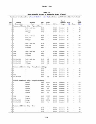
![ASME 831.3-2022
Table A-1
Basic Allowable Stresses in Tension for Metals (Cont'd)
Numbers in Parentheses Refer to Notes for Tables A-1 and A-lM; Specifications Are ASTM Unless Otherwise Indicated
Minimum Minimum Basic Allowable Stress, S, ksi, at Metal Temperature, °F [Notes (1), (2a)]
Tensile Yield Min.
Line Strength, Strength, Max. Temp. to
No. ksi ksi Temp., °F 100 150 200 250 300 350 400 450 500 550 600 650 700
Titanium and Titanium Alloy - Pipes and Tubes
1 35 20 600 11.7 10.7 9.3 8.2 7.2 6.3 5.5 4.7 4.2 3.8 3.5
2 35 20 600 11.7 10.7 9.3 8.2 7.2 6.3 5.5 4.7 4.2 3.8 3.5
3 35 20 600 11.7 10.7 9.3 8.2 7.2 6.3 5.5 4.7 4.2 3.8 3.5
4 50 40 600 16.7 15.6 14.5 13.3 12.1 11.2 10.3 9.6 8.9 8.2 7.6
5 50 40 600 16.7 15.6 14.5 13.3 12.1 11.2 10.3 9.6 8.9 8.2 7.6
6 50 40 600 16.7 15.6 14.5 13.3 12.1 11.2 10.3 9.6 8.9 8.2 7.6
7 65 55 600 21.7 20.0 18.4 16.6 14.9 13.5 12.1 11.0 9.9 9.3 8.6
8 65 55 600 21.7 20.0 18.4 16.6 14.9 13.5 12.1 11.0 9.9 9.3 8.6
9 65 55 600 21.7 20.0 18.4 16.6 14.9 13.5 12.1 11.0 9.9 9.3 8.6
10 50 40 600 16.7 15.6 14.5 13.3 12.1 11.2 10.3 9.6 8.9 8.2 7.6
11 50 40 600 16.7 15.6 14.5 13.3 12.1 11.2 10.3 9.6 8.9 8.2 7.6
12 50 40 600 16.7 15.6 14.5 13.3 12.1 11.2 10.3 9.6 8.9 8.2 7.6
13 70 50 600 23.3 22.6 21.8 20.4 18.9 17.8 16.7 16.0 15.2 14.8 14.4
14 70 50 600 23.3 22.6 21.8 20.4 18.9 17.8 16.7 16.0 15.2 14.8 14.4
15 70 50 600 23.3 22.6 21.8 20.4 18.9 17.8 16.7 16.0 15.2 14.8 14.4
Titanium and Titanium Alloy - Plates, Sheets, and Strips
16 35 20 600 11.7 10.7 9.3 8.2 7.2 6.3 5.5 4.7 4.2 3.8 3.5
17 50 40 600 16.7 15.6 14.5 13.3 12.1 11.2 10.3 9.6 8.9 8.2 7.6
18 65 55 600 21.7 20.0 18.4 16.6 14.9 13.5 12.1 11.0 9.9 9.3 8.6
19 50 40 600 16.7 15.6 14.5 13.3 12.1 11.2 10.3 9.6 8.9 8.2 7.6
20 70 50 600 23.3 22.6 21.8 20.4 18.9 17.8 16.7 16.0 15.2 14.8 14.4
Titanium and Titanium Alloy - Forgings and Fittings
21 35 20 600 11.7 10.7 9.3 8.2 7.2 6.3 5.5 4.7 4.2 3.8 3.5
22 35 20 600 11.7 10.7 9.3 8.2 7.2 6.3 5.5 4.7 4.2 3.8 3.5
23 50 40 600 16.7 15.6 14.5 13.3 12.1 11.2 10.3 9.6 8.9 8.2 7.6
24 50 40 600 16.7 15.6 14.5 13.3 12.1 11.2 10.3 9.6 8.9 8.2 7.6
25 65 55 600 21.7 20.0 18.4 16.6 14.9 13.5 12.1 11.0 9.9 9.3 8.6
26 65 55 600 21.7 20.0 18.4 16.6 14.9 13.5 12.1 11.0 9.9 9.3 8.6
27 50 40 600 16.7 15.6 14.5 13.3 12.1 11.2 10.3 9.6 8.9 8.2 7.6
28 50 40 600 16.7 15.6 14.5 13.3 12.1 11.2 10.3 9.6 8.9 8.2 7.6
29 70 50 600 23.3 22.6 21.8 20.4 18.9 17.8 16.7 16.0 15.2 14.8 14.4
30 70 50 600 23.3 22.6 21.8 20.4 18.9 17.8 16.7 16.0 15.2 14.8 14.4
Titanium and Titanium Alloy - Bars
31 35 20 600 11.7 10.7 9.3 8.2 7.2 6.3 5.5 4.7 4.2 3.8 3.5
32 50 40 600 16.7 15.6 14.5 13.3 12.1 11.2 10.3 9.6 8.9 8.2 7.6
33 65 55 600 21.7 20.0 18.4 16.6 14.9 13.5 12.1 11.0 9.9 9.3 8.6
235](https://image.slidesharecdn.com/26162943-231229160810-282cb07a/85/ASME-B31-3-2022-Procces-piping-code-for-b31-3-262-320.jpg)
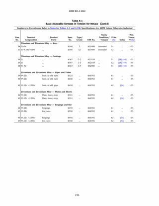
![ASME 831.3-2022
Table A-1
Basic Allowable Stresses in Tension for Metals (Cont'd)
Numbers in Parentheses Refer to Notes for Tables A-1 and A-lM; Specifications Are ASTM Unless Otherwise Indicated
Minimum Minimum Basic Allowable Stress, S, ksi, at Metal Temperature, °F [Notes (1), (2a)]
Tensile Yield Min.
Line Strength, Strength, Max. Temp. to
No. ksi ksi Temp., °F 100 150 200 250 300 350 400 450 500 550 600 650 700
Titanium and Titanium Alloy - Bars (Cont'd)
34 so 40 600 16.7 15.6 14.5 13.3 12.1 11.2 10.3 9.6 8.9 8.2 7.6
35 70 so 600 23.3 22.6 21.8 20.4 18.9 17.8 16.7 16.0 15.2 14.8 14.4
Titanium and Titanium Alloy - Castings
36 so 40 500 16.7 15.2 13.8 12.6 11.4 10.4 9.5 8.7 7.9
37 65 55 500 21.7 20.0 18.4 16.6 14.9 13.5 12.1 11.0 9.9
38 so 40 500 16.7 15.2 13.8 12.6 11.4 10.4 9.5 8.7 7.9
Zirconium and Zirconium Alloy - Pipes and Tubes
39 55 30 700 18.3 17.2 15.4 13.6 12.0 10.6 9.3 8.3 7.4 6.6 6.0 5.6 5.2
40 55 30 700 18.3 17.2 15.4 13.6 12.0 10.6 9.3 8.3 7.4 6.6 6.0 5.6 5.2
41 80 55 700 26.7 24.4 22.1 20.4 18.9 17.7 16.7 15.8 15.0 14.4 13.9 13.5 13.2
Zirconium and Zirconium Alloy - Plates and Sheets
42 55 30 700 18.3 17.2 15.4 13.6 12.0 10.6 9.3 8.3 7.4 6.6 6.0 5.6 5.2
43 80 55 700 26.7 24.4 22.1 20.4 18.9 17.7 16.7 15.8 15.0 14.4 13.9 13.5 13.2
Zirconium and Zirconium Alloy - Forgings and Bar
44 55 30 700 18.3 17.2 15.4 13.6 12.0 10.6 9.3 8.3 7.4 6.6 6.0 5.6 5.2
45 55 30 700 18.3 17.2 15.4 13.6 12.0 10.6 9.3 8.3 7.4 6.6 6.0 5.6 5.2
46 70 55 700 23.3 21.3 19.3 17.8 16.5 15.5 14.6 13.8 13.1 12.6 12.2 11.8 11.5
47 80 55 700 26.7 24.4 22.1 20.4 18.9 17.7 16.7 15.8 15.0 14.4 13.9 13.5 13.2
237](https://image.slidesharecdn.com/26162943-231229160810-282cb07a/85/ASME-B31-3-2022-Procces-piping-code-for-b31-3-264-320.jpg)
![ASME 831.3-2022
Table A-1
Basic Allowable Stresses in Tension for Metals (Cont'd)
Numbers in Parentheses Refer to Notes for Tables A-1 and A-lM; Specifications Are ASTM Unless Otherwise Indicated
Basic Allowable Stress, S, ksi, at Metal Temperature, 0f [Notes (1), (2a)]
Minimum Min.
Min. Minimum Yield Max. Temp.
Line. Temp., Tensile Strength, Temp., to
No. Of (6) Strength, ksi ksi" Of 100 150 200 250 300 350 400
Aluminum Alloy - Seamless Pipes and Tubes
-452 13 4.5 400 3.0 2.9 2.8 2.7 2.5 1.9 1.5
2 -452 13 4.5 400 3.0 2.9 2.8 2.7 2.5 1.9 1.5
3 -452 13 4.5 400 3.0 2.9 2.8 2.7 2.5 1.9 1.5
4 -452 13 4.5 400 3.0 2.9 2.8 2.7 2.5 1.9 1.5
5 -452 19 16 400 6.3 6.3 6.3 6.1 4.3 3.0 2.3
6 -452 26 23 400 8.7 8.7 8.7 8.4 4.3 3.0 2.3
7 -452 8.5 2.5 400 1.7 1.7 1.6 1.4 1.2 1.1 0.8
8 -452 8.5 2.5 400 1.7 1.7 1.6 1.4 1.2 1.1 0.8
9 -452 8.5 2.5 400 1.7 1.7 1.6 1.4 1.2 1.1 0.8
10 -452 8.5 2.5 400 1.7 1.7 1.6 1.4 1.2 1.1 0.8
11 -452 8.5 2.5 400 1.7 1.7 1.6 1.4 1.2 1.1 0.8
12 -452 8.5 2.5 400 1.7 1.7 1.6 1.4 1.2 1.1 0.8
13 -452 12 10 400 4.0 4.0 4.0 4.0 2.7 1.8 1.1
14 -452 11 3 400 2.0 2.0 2.0 1.9 1.7 1.3 1.0
15 -452 11 3 400 2.0 2.0 2.0 1.9 1.7 1.3 1.0
16 -452 11 3.5 400 2.3 2.3 2.3 2.3 1.7 1.3 1.0
17 -452 16 14 400 5.3 5.3 5.3 4.9 2.8 1.9 1.1
18 -452 14 5 400 3.3 3.2 3.1 3.0 2.7 1.9 1.5
19 -452 14 5 400 3.3 3.2 3.1 3.0 2.7 1.9 1.5
20 -452 14 5 400 3.3 3.2 3.1 3.0 2.7 1.9 1.5
21 -452 14 5 400 3.3 3.2 3.1 3.0 2.7 1.9 1.5
22 -452 14 5 400 3.3 3.2 3.1 3.0 2.7 1.9 1.5
23 -452 14 5 400 3.3 3.2 3.1 3.0 2.7 1.9 1.5
24 -452 20 17 400 6.7 6.7 6.5 4.8 4.3 3.0 2.3
25 -452 27 24 400 9.0 9.0 8.7 8.0 5.3 3.5 2.5
26 -452 27 24 400 9.0 9.0 8.7 8.0 5.3 3.5 2.5
27 -452 25 10 400 6.7 6.7 6.7 6.6 6.1 4.1 2.3
28 -452 25 10 400 6.7 6.7 6.7 6.6 6.1 4.1 2.3
29 -452 31 23 400 10.3 10.3 10.3 10.3 6.1 4.1 2.3
30 -452 34 26 400 11.3 11.3 11.3 11.3 6.1 4.1 2.3
31 -452 39 16 150 10.7 10.7
32 -452 39 16 150 10.7 10.7
33 -452 39 16 150 10.7 10.7
34 -452 39 16 150 10.7 10.7
35 -452 35 14 150 9.3 9.3
36 -452 35 14 150 9.3 9.3
37 -452 35 14 150 9.3 9.3
38 -452 35 14 150 9.3 9.3
39 -452 40 28 150 13.3 13.3
239](https://image.slidesharecdn.com/26162943-231229160810-282cb07a/85/ASME-B31-3-2022-Procces-piping-code-for-b31-3-266-320.jpg)
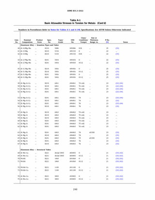
![ASME 831.3-2022
Table A-1
Basic Allowable Stresses in Tension for Metals (Cont'd)
Numbers in Parentheses Refer to Notes for Tables A-1 and A-lM; Specifications Are ASTM Unless Otherwise Indicated
Basic Allowable Stress, S, ksi, at Metal Temperature, 0f [Notes (1), (2a)]
Minimum Min.
Min. Minimum Yield Max. Temp.
Line. Temp., Tensile Strength, Temp., to
No. Of (6) Strength, ksi ksi" Of 100 150 200 250 300 350 400
Aluminum Alloy - Seamless Pipes and Tubes (Cont'd)
40 -452 44 34 150 14.7 14.7
41 -452 30 11 150 7.3 7.3
42 -452 39 29 150 13.3 13.0
43 -452 31 12 400 8.0 8.0 8.0 7.4 5.5 4.1 3.0
44 -452 31 12 400 8.0 8.0 8.0 7.4 5.5 4.1 3.0
45 -452 41 19 150 12.7 12.7
46 -452 41 19 150 12.7 12.7
47 -452 41 19 150 12.7 12.7
48 -452 41 19 150 12.7 12.7
49 -452 24 400 8.0 8.0 8.0 8.0 7.7 6.9 5.1
50 -452 24 400 8.0 8.0 8.0 8.0 7.7 6.9 5.1
51 -452 24 400 8.0 8.0 8.0 8.0 7.7 6.9 5.1
52 -452 24 400 8.0 8.0 8.0 8.0 7.7 6.9 5.1
53 -452 26 16 400 8.7 8.7 8.7 8.7 8.3 7.4 5.2
54 -452 30 16 400 10.0 10.0 10.0 9.9 9.5 8.4 5.2
55 -452 38 35 400 12.7 12.7 12.7 12.3 10.5 8.1 5.2
56 -452 42 35 400 14.0 14.0 14.0 13.6 11.7 8.9 5.2
57 -452 17 400 5.7 5.7 5.6 5.3 4.8 3.8 2.0
58 -452 17 400 5.7 5.7 5.6 5.3 4.8 3.8 2.0
59 -452 17 400 5.7 5.7 5.6 5.3 4.8 3.8 2.0
60 -452 17 400 5.7 5.7 5.6 5.3 4.8 3.8 2.0
61 -452 17 400 5.7 5.7 5.6 5.3 4.8 3.8 2.0
62 -452 17 400 5.7 5.7 5.6 5.3 4.8 3.8 2.0
63 -452 19 10 400 6.3 6.3 6.3 6.3 5.8 3.9 1.5
64 -452 22 10 400 6.7 6.5 6.5 6.3 6.3 4.5 1.7
65 -452 22 16 400 7.3 7.3 7.3 7.3 7.1 3.8 2.0
66 -452 30 25 400 10.0 10.0 10.0 9.1 7.2 3.4 2.0
67 -452 33 28 400 11.0 11.0 11.0 9.6 7.3 3.8 2.0
Aluminum Alloy - Structural Tubes
68 -452 13 4.5 400 3.0 2.9 2.8 2.7 2.5 1.9 1.5
69 -452 13 4.5 400 3.0 2.9 2.8 2.7 2.5 1.9 1.5
70 -452 8.5 2.5 400 1.7 1.7 1.6 1.4 1.2 1.1 0.8
71 -452 8.5 2.5 400 1.7 1.7 1.6 1.4 1.2 1.1 0.8
72 -452 11 3 400 2.0 2.0 2.0 1.9 1.7 1.3 1.0
73 -452 11 3 400 2.0 2.0 2.0 1.9 1.7 1.3 1.0
74 -452 14 5 400 3.3 3.2 3.1 3.0 2.7 1.9 1.5
75 -452 14 5 400 3.3 3.2 3.1 3.0 2.7 1.9 1.5
241](https://image.slidesharecdn.com/26162943-231229160810-282cb07a/85/ASME-B31-3-2022-Procces-piping-code-for-b31-3-268-320.jpg)
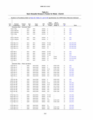
![ASME 831.3-2022
Table A-1
Basic Allowable Stresses in Tension for Metals (Cont'd)
Numbers in Parentheses Refer to Notes for Tables A-1 and A-lM; Specifications Are ASTM Unless Otherwise Indicated
Basic Allowable Stress, S, ksi, at Metal Temperature, 0f [Notes (1), (2a)]
Minimum Min.
Min. Minimum Yield Max. Temp.
Line. Temp., Tensile Strength, Temp., to
No. Of (6) Strength, ksi ksi" Of 100 150 200 250 300 350 400
Aluminum Alloy - Structural Tubes (Cont'd)
76 -452 25 10 400 6.7 6.7 6.7 6.6 6.1 4.1 2.3
77 -452 39 16 150 10.7 10.7
78 -452 35 14 150 9.3 9.3
79 -452 30 11 150 7.3 7.3
80 -452 31 12 400 8.0 8.0 8.0 7.4 5.5 4.1 3.0
81 -452 41 19 150 12.7 12.7
82 -452 24 400 8.0 8.0 8.0 8.0 7.7 6.9 5.1
83 -452 24 400 8.0 8.0 8.0 8.0 7.7 6.9 5.1
84 -452 26 16 400 8.7 8.7 8.7 8.7 8.3 7.4 5.2
85 -452 38 35 400 12.7 12.7 12.7 12.3 10.5 8.1 5.2
86 -452 17 400 5.7 5.7 5.6 5.3 4.8 3.8 2.0
87 -452 17 400 5.7 5.7 5.6 5.3 4.8 3.8 2.0
88 -452 17 400 5.7 5.7 5.6 5.3 4.8 3.8 2.0
89 -452 19 10 400 6.3 6.3 6.3 6.3 5.8 3.9 1.5
90 -452 22 16 400 7.3 7.3 7.3 7.3 7.1 3.8 2.0
91 -452 30 25 400 10.0 10.0 10.0 9.1 7.2 3.4 2.0
Aluminum Alloy - Plates and Sheets
92 -452 13 4.5 400 3.0 2.9 2.8 2.7 2.5 1.9 1.5
93 -452 14 5 400 3.3 3.2 3.1 3.0 2.7 1.9 1.5
94 -452 15 6 400 4.0 3.9 3.7 3.6 2.7 1.9 1.5
95 -452 16 11 400 5.3 5.3 5.2 4.9 4.3 3.0 2.3
96 -452 17 12 400 5.7 5.7 5.7 5.7 4.3 3.0 2.3
97 -452 19 16 400 6.3 6.3 6.3 6.1 4.3 3.0 2.3
98 -452 20 17 400 6.7 6.7 6.7 6.5 4.3 3.0 2.3
99 -452 21 8 400 5.3 5.3 5.3 5.3 5.3 3.8 2.3
100 -452 22 8.5 400 5.7 5.6 5.6 5.6 5.6 3.8 2.3
101 -452 22 8.5 400 5.7 5.6 5.6 5.6 5.6 3.8 2.3
102 -452 23 9 400 6.0 6.0 6.0 6.0 5.7 3.8 2.3
103 -452 27 20 400 9.0 9.0 9.0 9.0 5.7 3.8 2.3
104 -452 28 21 400 9.3 9.3 9.3 9.3 5.7 3.8 2.3
105 -452 31 24 400 10.3 10.3 10.3 10.3 5.7 3.8 2.3
106 -452 32 25 400 10.7 10.7 10.7 10.7 5.7 3.8 2.3
107 -452 24 400 8.0 8.0 8.0 8.0 7.7 6.9 5.1
108 -452 24 400 8.0 8.0 8.0 8.0 7.7 6.9 5.1
109 -452 27 14 400 9.0 9.0 9.0 8.9 8.6 7.6 5.2
110 -452 27 14 400 9.0 9.0 9.0 8.9 8.6 7.6 5.2
111 -452 30 16 400 9.0 9.0 9.0 8.9 8.5 8.4 5.2
112 -452 38 32 400 12.7 12.7 12.7 12.3 10.6 8.1 5.2
113 -452 38 32 400 12.7 12.7 12.7 12.3 10.6 8.1 5.2
114 -452 42 35 400 14.0 14.0 14.0 13.6 11.7 8.9 5.2
243](https://image.slidesharecdn.com/26162943-231229160810-282cb07a/85/ASME-B31-3-2022-Procces-piping-code-for-b31-3-270-320.jpg)
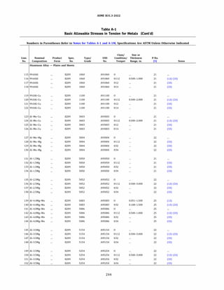
![ASME 831.3-2022
Table A-1
Basic Allowable Stresses in Tension for Metals (Cont'd)
Numbers in Parentheses Refer to Notes for Tables A-1 and A-lM; Specifications Are ASTM Unless Otherwise Indicated
Basic Allowable Stress, S, ksi, at Metal Temperature, 0f [Notes (1), (2a)]
Minimum Min.
Min. Minimum Yield Max. Temp.
Line. Temp., Tensile Strength, Temp., to
No. Of (6) Strength, ksi ksi" Of 100 150 200 250 300 350 400
Aluminum Alloy - Plates and Sheets (Cont'd)
115 -452 8 2.5 400 1.7 1.6 1.6 1.4 1.2 1.1 0.8
116 -452 10 5 400 3.3 3.2 2.9 2.5 2.0 1.5 0.9
117 -452 11 9 400 3.7 3.7 3.4 3.1 2.7 1.8 1.1
118 -452 12 10 400 4.0 4.0 4.0 4.0 2.7 1.8 1.1
119 -452 11 3.5 400 2.3 2.3 2.3 2.3 1.7 1.3 1.0
120 -452 12 5 400 3.3 3.3 3.3 3.2 2.4 1.7 1.0
121 -452 14 11 400 4.7 4.7 4.6 3.8 2.8 1.9 1.1
122 -452 16 14 400 5.3 5.3 5.3 4.9 2.8 1.9 1.1
123 -452 14 5 400 3.3 3.2 3.1 3.0 2.7 1.9 1.5
124 -452 15 6 400 4.0 3.9 3.7 3.6 2.7 1.9 1.5
125 -452 17 12 400 5.7 5.7 5.6 5.2 4.3 3.0 2.3
126 -452 20 17 400 6.7 6.7 6.7 6.5 4.3 3.0 2.3
127 -452 22 8.5 400 5.7 5.7 5.7 5.7 5.7 3.8 2.3
128 -452 23 9 400 6.0 6.0 6.0 6.0 5.8 3.8 2.3
129 -452 28 21 400 9.3 9.3 9.3 9.3 5.7 3.8 2.3
130 -452 32 25 400 10.7 10.7 10.7 10.7 5.7 3.8 2.3
131 -452 18 6 400 4.0 4.0 4.0 4.0 4.0 2.8 1.4
132 -452 20 8 400 5.3 5.3 5.3 5.2 5.2 2.8 1.4
133 -452 22 16 400 7.3 7.3 7.3 7.3 5.3 2.8 1.4
134 -452 25 20 400 8.3 8.3 8.3 7.8 5.3 2.8 1.4
135 -452 25 9.5 400 6.3 6.3 6.3 6.2 6.1 4.1 2.3
136 -452 25 9.5 400 6.3 6.3 6.3 6.3 6.1 4.1 2.3
137 -452 31 23 400 10.3 10.3 10.3 10.3 6.1 4.1 2.3
138 -452 34 26 400 11.3 11.3 11.3 11.3 6.1 4.1 2.3
139 -452 40 18 150 12.0 12.0
140 -452 44 31 150 14.7 14.7
141 -452 35 14 150 9.3 9.3
142 -452 35 16 150 9.3 9.3
143 -452 40 28 150 13.3 13.3
144 -452 44 34 150 14.7 14.7
145 -452 30 11 150 7.3 7.3
146 -452 30 11 150 7.3 7.3
147 -452 36 26 150 12.0 12.0
148 -452 39 29 150 13.0 13.0
149 -452 30 11 150 7.3 7.3
150 -452 30 11 150 7.3 7.3
151 -452 36 26 150 12.0 12.0
152 -452 39 29 150 13.0 13.0
245](https://image.slidesharecdn.com/26162943-231229160810-282cb07a/85/ASME-B31-3-2022-Procces-piping-code-for-b31-3-272-320.jpg)
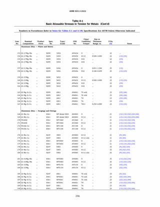
![ASME 831.3-2022
Table A-1
Basic Allowable Stresses in Tension for Metals (Cont'd)
Numbers in Parentheses Refer to Notes for Tables A-1 and A-lM; Specifications Are ASTM Unless Otherwise Indicated
Basic Allowable Stress, S, ksi, at Metal Temperature, °F [Notes (1), (2a)]
Minimum Min.
Min. Minimum Yield Max. Temp.
Line. Temp., Tensile Strength, Temp., to
No. Of (6) Strength, ksi ksi" Of 100 150 200 250 300 350 400
Aluminum Alloy - Plates and Sheets (Cont'd)
153 -452 31 12 400 8.0 8.0 8.0 7.4 5.5 4.1 3.0
154 -452 31 12 400 8.0 8.0 8.0 7.4 5.5 4.1 3.0
155 -452 36 26 400 12.0 12.0 12.0 7.5 5.5 4.1 3.0
156 -452 39 29 400 13.0 13.0 13.0 7.5 5.5 4.1 3.0
157 -452 42 19 150 12.7 12.7
158 -452 46 33 150 15.3 15.3
159 -452 25 9.5 400 6.3 6.3 6.3 6.2 6.1 4.1 2.3
160 -452 25 9.5 400 6.3 6.3 6.3 6.3 6.1 4.1 2.3
161 -452 31 23 400 10.3 10.3 10.3 10.3 6.1 4.1 2.3
162 -452 34 26 400 11.3 11.3 11.3 11.3 6.1 4.1 2.3
163 -452 24 400 8.0 8.0 8.0 8.0 7.7 6.9 5.1
164 -452 24 400 8.0 8.0 8.0 8.0 7.7 6.9 5.1
165 -452 30 16 400 10.0 10.0 10.0 9.9 9.5 8.4 5.2
166 -452 42 35 400 14.0 14.0 14.0 13.6 11.7 8.9 5.2
167 -452 42 35 400 14.0 14.0 14.0 13.6 11.7 8.9 5.2
Aluminum Alloy - Forgings and Fittings
168 -452 13 4.5 400 3.0 2.9 2.8 2.7 2.5 1.9 1.5
169 -452 13 4.5 400 3.0 2.9 2.8 2.7 2.5 1.9 1.5
170 -452 8 2.5 400 1.7 1.6 1.6 1.4 1.2 1.1 0.8
171 -452 8 2.5 400 1.7 1.6 1.6 1.4 1.2 1.1 0.8
172 -452 11 3 400 2.0 2.0 2.0 1.9 1.7 1.3 1.0
173 -452 11 3 400 2.0 2.0 2.0 1.9 1.7 1.3 1.0
174 -452 14 5 400 3.3 3.2 3.1 3.0 2.7 1.9 1.5
175 -452 14 5 400 3.3 3.2 3.1 3.0 2.7 1.9 1.5
176 -452 14 5 400 3.3 3.2 3.1 3.0 2.7 1.9 1.5
177 -452 14 5 400 3.3 3.2 3.1 3.0 2.7 1.9 1.5
178 -452 39 16 150 10.7 10.7
179 -452 39 16 150 10.7 10.7
180 -452 39 16 150 10.7 10.7
181 -452 39 16 150 10.7 10.7
182 -452 39 16 150 10.7 10.7
183 -452 30 11 150 7.3 7.3
184 -452 30 11 150 7.3 7.3
185 -452 24 400 8.0 8.0 8.0 8.0 7.7 6.9 5.1
186 -452 24 400 8.0 8.0 8.0 8.0 7.7 6.9 5.1
187 -452 24 400 8.0 8.0 8.0 8.0 7.7 6.9 5.1
188 -452 26 16 400 8.7 8.7 8.7 8.7 8.3 7.4 5.2
189 -452 38 35 400 12.7 12.7 12.7 12.3 10.5 8.1 5.2
190 -452 38 35 400 12.7 12.7 12.7 12.3 10.5 8.1 5.2
247](https://image.slidesharecdn.com/26162943-231229160810-282cb07a/85/ASME-B31-3-2022-Procces-piping-code-for-b31-3-274-320.jpg)
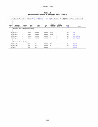
![ASME 831.3-2022
Table A-1
Basic Allowable Stresses in Tension for Metals (Cont'd)
Numbers in Parentheses Refer to Notes for Tables A-1 and A-lM; Specifications Are ASTM Unless Otherwise Indicated
Basic Allowable Stress, S, ksi, at Metal Temperature, °F [Notes (1), (2a)]
Minimum Min.
Min. Minimum Yield Max. Temp.
Line. Temp., Tensile Strength, Temp., to
No. Of (6) Strength, ksi ksi" Of 100 150 200 250 300 350 400
Aluminum Alloy - Forgings and Fittings (Cont'd)
191 -452 17 400 5.7 5.7 5.7 5.7 5.5 3.8 2.0
192 -452 17 400 5.7 5.7 5.7 5.7 5.5 3.8 2.0
193 -452 18 9 400 6.0 5.9 5.8 5.7 5.5 3.7 1.4
194 -452 30 25 400 10.0 10.0 10.0 9.1 7.2 3.4 2.0
Aluminum Alloy - Castings
195 -452 25 18 400 8.3 8.3 8.3 8.1 7.3 5.5 2.4
196 -452 30 20 250 10.0 10.0 10.0 8.4
197 -452 17 7 400 4.7 4.7 4.7 4.7 4.7 4.7 3.5
249](https://image.slidesharecdn.com/26162943-231229160810-282cb07a/85/ASME-B31-3-2022-Procces-piping-code-for-b31-3-276-320.jpg)
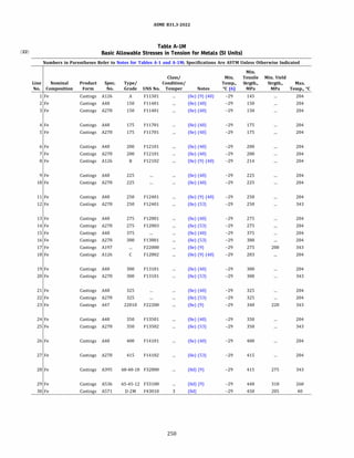
![ASME 831.3-2022
Table A-IM
Basic Allowable Stresses in Tension for Metals (SI Units)
Numbers in Parentheses Refer to Notes for Tables A-1 and A-lM; Specifications Are ASTM Unless Otherwise Indicated
Basic Allowable Stress, S, MPa, at Metal Temperature, °C (Notes (1), (2b)]
Min.
Line Temp. to
No. 40 65 100 125 150 175 200 225 250 275 300 325 350
1 13.8 13.8 13.8 13.8 13.8 13.8 13.8 13.8
2 15.0 15.0 15.0 15.0 15.0 15.0 15.0 15.0
3 15.0 15.0 15.0 15.0 15.0 15.0 15.0 15.0
4 17.5 17.5 17.5 17.5 17.5 17.5 17.5 17.5
5 17.5 17.5 17.5 17.5 17.5 17.5 17.5 17.5
6 20.0 20.0 20.0 20.0 20.0 20.0 20.0 20.0
7 20.0 20.0 20.0 20.0 20.0 20.0 20.0 20.0
8 20.7 20.7 20.7 20.7 20.7 20.7 20.7 20.7
9 22.5 22.5 22.5 22.5 22.5 22.5 22.5 22.5
10 22.5 22.5 22.5 22.5 22.5 22.5 22.5 22.5
11 25.0 25.0 25.0 25.0 25.0 25.0 25.0 25.0
12 25.0 25.0 25.0 25.0 25.0 25.0 25.0 25.0 27.6 27.6 27.6 27.6 27.6
13 27.5 27.5 27.5 27.5 27.5 27.5 27.5 27.5
14 27.5 27.5 27.5 27.5 27.5 27.5 27.5 27.5
15 37.5 37.5 37.5 37.5 37.5 37.5 37.5 37.5
16 38.0 38.0 38.0 38.0 38.0 38.0 38.0 38.0
17 55.2 55.2 55.2 55.2 55.2 55.2 55.2 55.2 55.2 55.2 55.2 55.2 55.2
18 27.6 27.6 27.6 27.6 27.6 27.6 27.6 27.6
19 30.0 30.0 30.0 30.0 30.0 30.0 30.0 30.0
20 30.0 30.0 30.0 30.0 30.0 30.0 30.0 30.0 34.5 34.5 34.5 34.5 34.5
21 32.5 32.5 32.5 32.5 32.5 32.5 32.5 32.5
22 32.5 32.5 32.5 32.5 32.5 32.5 32.5 32.5
23 68.0 68.0 68.0 68.0 68.0 68.0 68.0 68.0 68.0 68.0 68.0 68.0 68.0
24 35.0 35.0 35.0 35.0 35.0 35.0 35.0 35.0
25 35.0 35.0 35.0 35.0 35.0 35.0 35.0 35.0 41.4 41.4 41.4 41.4 41.4
26 37.5 37.5 40.0 40.0 40.0 40.0 40.0 40.0
27 41.5 41.5 41.5 41.5 41.5 41.5 41.5 41.5
28 137 133 128 125 122 119 116 112 109 106 103 98.0 93.5
29 149 149 149 149 149 149 148 148 148 147
30 137
251](https://image.slidesharecdn.com/26162943-231229160810-282cb07a/85/ASME-B31-3-2022-Procces-piping-code-for-b31-3-278-320.jpg)
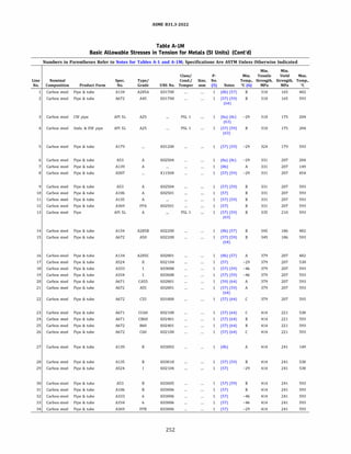
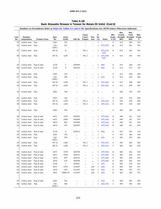
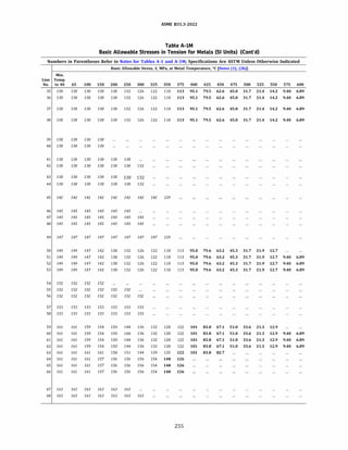
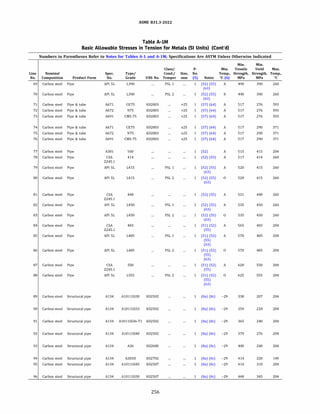
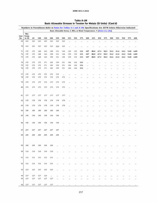
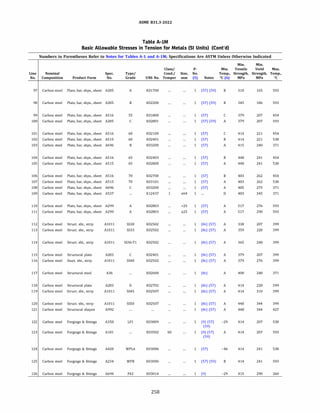
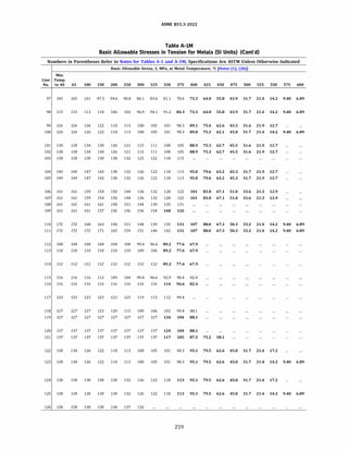
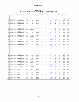
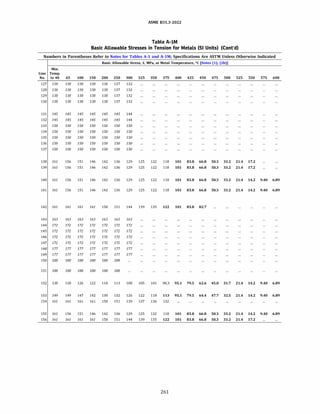
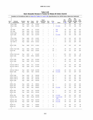
![ASME 831.3-2022
Table A-IM
Basic Allowable Stresses in Tension for Metals (SI Units) (Cont'd)
Numbers in Parentheses Refer to Notes for Tables A-1 and A-lM; Specifications Are ASTM Unless Otherwise Indicated
Basic Allowable Stress, S, MPa, at Metal Temperature, °C [Notes (1), (2b)]
Min.
Line Temp.
No. to 40 65 100 125 150 175 200 225 250 275 300 325 350 375 400 425 450 475 500 525 550 575 600 625 650
126 126 126 126 124 122 120 119 117 115 114 112 110 108 106 103 100 97.1 74.4 49.9 40.7 ...
2 126 126 126 126 126 126 126 126 126 126 125 123 121 119 116 114 110 107 74.4 49.9 40.7 ...
3 126 126 126 126 124 122 120 119 117 115 114 112 110 108 106 103 100
4 126 126 126 126 124 122 120 119 117 115 114 112 110 108 106 103 100
5 126 126 126 126 124 122 120 119 117 115 114 112 110 108 106 103 100
97.1 68.0 42.3 30.5 23.2 16.5
97.1 68.0 42.3 30.5 23.2 16.5
97.1 93.5 49.9 34.7 23.9 17.2
6 126 126 123 122 122 122 122 121 120 118 116 115 114 112 110 109 106 104 92.1 61.1 40.4 26.4 17.4 11.6 7.58
7 138 133 129 126 124 122 120 119 117 115 114 112 110 108 106 103 100 97.1 74.4 49.9 34.3 23.2 16.5
8 138 133 129 127 125 124 122 121 120 118 117 115 114 112 110 107 103 88.4 74.7 53.7 35.6 23.2 16.5
9 138 133 129 127 125 124 122 121 120 118 117 115 114 112 110 107 103 88.4 74.7 53.7 35.6 23.2 16.5
10 138 129 124 120 117 115 112 110 109 107 106 105 103 102 100 98.7 96.8 94.6 92.0 61.1 40.4 26.4 17.4 11.6 7.58
11 138 129 124 122 120 119 119 118 118 117 117 116 114 112 110 106 103 80.6 61.7 46.4 34.7 25.5 17.8 11.4 6.89
12 138 132 128 126 125 124 124 124 124 124 124 124 124 124 123 122 121 89.2 68.8 54.2 43.4 34.0 25.1 17.1 10.3
13 138
14 138 132 128 126 125 124 124 124 124 124 124 124 124 124 123 122 121 118 74.7 53.3 36.0 24.6 15.5 9.21 6.89
15 138 138 132 128 125 122 120 118 116 114 113 112 110 109 107 105 103 101 92.1 61.1 40.4 26.4 17.4 11.6 7.58
16 138 138 132 128 125 122 120 118 116 114 113 112 110 109 107 105 103 101 92.1 61.1 40.4 26.4 17.4 11.6 7.58
17 138 131 126 124 121 119 116 115 113 111 109 107 106 104 102 99.6 97.2 94.5 73.7 52.0 36.3 25.2 17.6 12.3 8.27
18 138 131 126 124 121 119 116 115 113 111 109 107 106 104 102 99.6 97.2 94.5 73.7 52.0 36.3 25.2 17.6 12.3 8.27
19 138 138 138 138 138 138 136 134 131 129 127 125 123 121 119 116 113 104 73.7 52.0 36.3 25.2 17.6 12.3 8.27
20 138 129 124 122 120 119 119 118 118 117 117 116 114 112 110 106 103 80.6 61.7 46.4 34.7 25.5 17.8 11.4 6.89
21 138 129 124 122 120 119 119 118 118 117 117 116 114 112 110 106 103 80.6 61.7 46.4 34.7 25.5 17.8 11.4 6.89
22 138 129 124 122 120 119 119 118 118 117 117 116 114 112 110 106 103 80.6 61.7 46.4 34.7 25.5 17.8 11.4 6.89
23 138 129 124 122 120 119 119 118 118 117 117 116 114 112 110 106 103
24 138 129 124 122 120 119 119 118 118 117 117 116 114 112 110 106 103
25 138 129 124 122 120 119 119 118 118 117 117 116 114 112 110 106 103
26 138 129 124 122 120 119 119 118 118 117 117 116 114 112 110 106 103
27 138 129 124 122 120 119 119 118 118 117 117 116 114 112 110 106 103
28 138 132 128 126 125 124 124 124 124 124 124 124 124 124 123 122 121
29 138 132 128 126 125 124 124 124 124 124 124 124 124 124 123 122 121
30 138 132 128 126 125 124 124 124 124 124 124 124 124 124 123 122 121
31 138 132 128 126 125 124 124 124 124 124 124 124 124 124 123 122 121
80.6 61.7 46.4 34.7 25.5 17.8 11.4 6.89
80.6 61.7 46.4 34.7 25.5 17.8 11.4 6.89
98.3 83.2 60.2 42.9 29.9 20.6 14.4 10.3
98.3 83.2 60.2 42.9 29.9 20.6 14.4 10.3
98.3 83.2 60.2 42.9 29.9 20.6 14.4 10.3
89.2 68.8 54.2 43.4 34.0 25.1 17.1 10.3
89.2 68.8 54.2 43.4 34.0 25.1 17.1 10.3
89.2 68.8 54.2 43.4 34.0 25.1 17.1 10.3
99.6 80.9 63.3 47.5 34.2 23.5 15.3 9.65
32 138 132 128 126 125 124 124 124 124 124 124 124 124 124 123 122 121 99.6 80.9 63.3 47.5 34.2 23.5 15.3 9.65
33 138 132 128 126 125 124 124 124 124 124 124 124 124 124 123 122 121 99.6 80.9 63.3 47.5 34.2 23.5 15.3 9.65
34 145
35 145
263](https://image.slidesharecdn.com/26162943-231229160810-282cb07a/85/ASME-B31-3-2022-Procces-piping-code-for-b31-3-290-320.jpg)
![ASME 831.3-2022
Table A-IM
Basic Allowable Stresses in Tension for Metals (SI Units) (Cont'd)
Numbers in Parentheses Refer to Notes for Tables A-1 and A-lM; Specifications Are ASTM Unless Otherwise Indicated
Min. Min.
Class/ Min. Tensile Yield Max.
Line Nominal Product Spec. Type/ UNS Condition/ Size, P-No. Temp., Strength, Strength, Temp.,
No. Composition Form No. Grade No. Temper mm (5) Notes �C (6) MPa MPa oc
36 2'l4Ni Pipe A333 7 K21903 9A -73 448 241 593
37 21;.Ni Pipe A334 7 K21903 9A -73 448 241 593
38 3Y,Ni Pipe A333 3 K31918 98 -101 448 241 593
39 3Y,Ni Pipe A334 3 K31918 98 -101 448 241 593
40 C-1
/2Mo Pipe A426 CPl ]12521 3 (58) -29 448 241 593
41 c-1!,Mo Pipe A672 L65 K11820 3 (11) (58) (64) -29 448 255 593
42 C-1
/2Mo Pipe A691 CM-65 K11820 3 (11) (58) (64) -29 448 255 593
43 2Y4Ni Pipe A671 CFB70 K22103 9A (11) (46) (64) -29 483 276 40
44 3Y,Ni Pipe A671 CFE70 K32018 98 (11) (46) (64) -29 483 276 40
45 C-1
/2Mo Pipe A672 L70 K12020 3 (11) (58) (64) -29 483 276 593
46 C-1
/2Mo Pipe A691 CM-70 K12020 3 (11) (58) (64) -29 483 276 593
47 l'l4Cr-'l2Mo Pipe A426 CP11 ]12072 4 -29 483 276 649
48 21;.Cr-lMo Pipe A426 CP22 ]21890 SA (15) -29 483 276 649
49 C-1
/2Mo Pipe A672 L75 K12320 3 (11) (58) (64) -29 517 296 593
so c-1!,Mo Pipe A691 CM-75 K12320 3 (11) (58) (64) -29 517 296 593
51 9Cr-1Mo-V Pipe A335 P91 K90901 ,,75 lSE -29 586 414 649
52 9Cr-1Mo-V Pipe A691 91 K90901 ,,75 lSE (11) (64) -29 586 414 649
53 5Cr-1
/2Mo Pipe A426 CPS ]42045 SB -29 621 414 649
54 9Cr-1Mo Pipe A426 CP9 ]82090 SB -29 621 414 649
55 9Ni Pipe A333 8 K81340 llA (47) -196 689 517 93
56 9Ni Pipe A334 8 K81340 11A -196 689 517 93
57 Y2Cr-1
/2Mo Plate A387 2 K12143 3 -29 379 228 538
58 1Cr-1
/2Mo Plate A387 12 K11757 4 -29 379 228 649
59 9Cr-1Mo Plate A387 9 K90941 SB -29 414 207 649
60 lY4Cr-'!2Mo-Si Plate A387 11 K11789 4 -29 414 241 649
61 5Cr-1
/2Mo Plate A387 5 K41545 SB -29 414 207 649
62 3Cr-1Mo Plate A387 21 K31545 SA -29 414 207 649
63 21
/4Cr-1Mo Plate A387 22 K21590 SA (15) -29 414 207 649
64 2Y4Ni Plate A203 A K21703 9A (12) (46) -29 448 255 538
65 3Y,Ni Plate A203 D K31718 98 (12) (46) -29 448 255 538
66 C-1
/2Mo Plate A204 A K11820 3 (58) -29 448 255 593
67 1Cr-1
/2Mo Plate A387 12 K11757 2 4 -29 448 276 649
68 2'l4Ni Plate A203 B K22103 9A (12) (46) -29 483 276 538
69 3Y,Ni Plate A203 E K32018 98 (12) (46) -29 483 276 538
264](https://image.slidesharecdn.com/26162943-231229160810-282cb07a/85/ASME-B31-3-2022-Procces-piping-code-for-b31-3-291-320.jpg)
![ASME 831.3-2022
Table A-IM
Basic Allowable Stresses in Tension for Metals (SI Units) (Cont'd)
Numbers in Parentheses Refer to Notes for Tables A-1 and A-lM; Specifications Are ASTM Unless Otherwise Indicated
Basic Allowable Stress, S, MPa, at Metal Temperature, °C [Notes (1), (2b)]
Min.
Line Temp.
No. to 40 65 100 125 150 175 200 225 250 275 300 325 350 375 400 425 450 475 500 525 550 575 600 625 650
36 149 149 147 144 142 140 138 135 132 128 124 119 113 107 95.1 79.5 64.4 48.8 35.4 22.6 14.2 9.40 6.89 ...
37 149 149 147 144 142 140 138 135 132 128 124 119 113 107 95.1 79.5 64.4 48.8 35.4 22.6 14.2 9.40 6.89 ...
38 149 149 147 144 142 140 138 135 132 128 124 119 113 107 95.1 79.5 64.4 48.8 35.4 22.6 14.2 9.48 7.06 ...
39 149 149 147 144 142 140 138 135 132 128 124 119 113 107 95.1 79.5 64.4 48.8 35.4 22.6 14.2 9.48 7.06 ...
40 149 149 149 148 145 143 140 138 137 135 133 131 129 126 123 120 117 109 68.0 42.3 30.5 23.2 16.5
41 149 149 149 149 149 149 148 146 144 142 140 138 136 133 131 127 124 109 68.0 42.3 30.5 23.2 16.5
42 149 149 149 149 149 149 148 146 144 142 140 138 136 133 131 127 124 109 68.0 42.3 30.5 23.2 16.5
43 161
44 161
45 161 161 161 161 161 161 161 158 156 154 152 149 147 144 141 138 134 109 68.0 42.3 30.5 23.2 16.5
46 161 161 161 161 161 161 161 158 156 154 152 149 147 144 141 138 134 109 68.0 42.3 30.5 23.2 16.5
47 161
48 161
161 161 161 161 158 155 153 150 148 146 143 141 138 136 133 130 104
161 160 157 156 156 156 156 156 156 156 156 156 156 156 156 156 119
73.7 52.0 36.3 25.2 17.6 12.3
88.4 64.0 44.6 30.0 19.7 12.8
49 172 172 172 172 172 172 172 170 168 165 163 161 158 155 152 148 144 109 68.0 42.3 30.5 23.2 16.5
so 172 172 172 172 172 172 172 170 168 165 163 161 158 155 152 148 144 109 68.0 42.3 30.5 23.2 16.5
8.27
8.27
51 195 195 195 195 195 195 195 195 194 193 192 190 187 183 178 172 165 156 147 137 115 87.0 64.7 45.1 29.6
52 195 195 195 195 195 195 195 195 194 193 192 190 187 183 178 172 165 156 147 137 115 87.0 64.7 45.1 29.6
53 207 207 205 202 200 199 199 199 198 198 196 194 191 187 182 176 169
54 207 207 205 202 200 199 199 199 198 198 196 194 191 187 182 176 169
55 230 230 230
56 230 230 230
80.6 61.7 46.4 34.7 25.5 17.8 11.4 6.89
160 87.5 61.2 42.9 29.9 20.6 14.4 10.3
57 126 126 126 126 126 126 126 126 126 126 125 123 121 119 116 114 110 107 74.4 49.9 40.7 ...
58 126 126 123 122 122 122 122 121 120 118 116 115 114 112 110 109 106 104 92.1 61.1 40.4 26.4 17.4 11.6 7.58
59 138 129 124 122 120 119 119 118 118 117 117 116 114 112 110 106 103 98.3 83.2 60.2 42.9 29.9 20.6 14.4 10.3
60 138 138 138 138 138 138 136 134 131 129 127 125 123 121 119 116 113 104 73.7 52.0 36.3 25.2 17.6 12.3 8.27
61 138 129 124 122 120 119 119 118 118 117 117 116 114 112 110 106 103 80.6 61.7 46.4 34.7 25.5 17.8 11.4 6.89
62 138 130 126 123 121 119 117 116 115 114 112 111 110 109 107 105 103 89.2 68.8 54.2 43.4 34.0 25.1 17.1 10.3
63 138 132 128 126 125 124 124 124 124 124 124 124 124 124 123 122 121 99.6 80.9 63.3 47.5 34.2 23.5 15.3 9.65
64 149 149 149 149 149 148 146 143 140 136 131 126 120 113 95.1 79.5 64.4 48.8 35.4 22.6 17.2 ...
65 149 149 149 149 149 148 146 143 140 136 131 126 120 113 95.1 79.5 64.4 48.8 35.4 22.6 17.2 ...
66 149 149 149 149 149 149 148 146 144 142 140 138 136 133 131 127 124 109 68.0 42.3 30.5 23.2 16.5
67 149 149 146 144 144 144 144 144 144 143 141 139 138 136 134 132 129 126 92.1 61.1 40.4 26.4 17.4 11.6 7.58
68 161
69 161
161 161 161 161 160 158 155 151 147 142 136 130 113 95.1 79.5 64.4 48.8 35.4 22.6 17.2 ...
161 161 161 161 160 158 155 151 147 142 136 130 122 101 83.8 66.8 49.2 35.4 22.6 17.2 ...
265](https://image.slidesharecdn.com/26162943-231229160810-282cb07a/85/ASME-B31-3-2022-Procces-piping-code-for-b31-3-292-320.jpg)
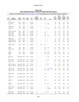
![ASME 831.3-2022
Table A-IM
Basic Allowable Stresses in Tension for Metals (SI Units) (Cont'd)
Numbers in Parentheses Refer to Notes for Tables A-1 and A-lM; Specifications Are ASTM Unless Otherwise Indicated
Basic Allowable Stress, S, MPa, at Metal Temperature, °C [Notes (1), (2b)]
Min.
Line Temp.
No. to 40 65 100 125 150 175 200 225 250 275 300 325 350 375 400 425 450 475 500 525 550 575 600 625 650
70 161 161 161 161 161 161 161 161 161 161 161 161 161 161 159 155 151 146 93.5 49.9 40.7 ...
71 161 161 161 161 161 161 161 158 156 154 152 149 147 144 141 138 134 109 68.0 42.3 30.5 23.2 16.5
72 172 172 172 172 172 172 172 172 172 172 172 172 171 168 165 160 154 104 68.0 42.3 33.1 ...
73 172 172 172 172 172 172 172 170 168 165 163 161 158 155 152 148 144 109 68.0 42.3 30.5 23.2 16.5
74 172 172 172 172 172 172 172 172 169 166 164 161 159 156 153 149 146
75 172 172 171 169 167 166 165 165 165 164 164 162 159 156 130 126 104
104 73.7 52.0 36.3 25.2 17.6 12.3
80.6 61.7 46.4 34.7 25.5 17.8 11.4
8.27
6.89
76 172 172 171 168 167 167 167 167 167 167 167 167 167 167 167 167 167 98.2 73.5 54.7 40.6 29.2 20.6 15.2 8.96
77 172 172 171 168 167 167 167 167 167 167 167 167 167 167 167 167 167 119 88.4 64.0 44.6 30.0 19.7 12.8 8.27
78 184 184 184 184 184 184 184 184 184 184 184 184 184 184 183 178 172 104 68.0 42.3 33.1 ...
79 184 184 184 184 184 184 184 184 184 184 184 184 184 184 183 178 172 104 68.0 42.3 33.1 ...
80 184 184 184 184 184 184 184 184 184 184 184 184 184 184 183 178 172 104 68.0 42.3 33.1 ...
Bl 195 195 195 195 195 195 195 195 194 193 192 190 187 183 178 172 165 156 147 137 115 87.0 64.7 45.1 29.6
82 230
83 218 218 218
84 230 230 230
85 230 230 230
86 126 126 126 126 124 122 120 119 117 115 114 112 110 108 106 103 100 97.1 68.0 42.3 30.5 23.2 16.5
87 138 129 124 120 117 115 112 110 109 107 106 105 103 102 100 98.7 96.B 94.6 92.0 61.1 40.4 26.4 17.4 11.6 7.58
88 138 138 132 128 125 122 120 118 116 114 113 112 110 109 107 105 103 101 92.1 61.1 40.4 26.4 17.4 11.6 7.58
89 138 131 126 124 121 119 116 115 113 111 109 107 106 104 102 99.6 97.2 94.5 73.7 52.0 36.3 25.2 17.6 12.3 8.27
90 138 131 126 124 121 119 116 115 113 111 109 107 106 104 102 99.6 97.2 94.5 73.7 52.0 36.3 25.2 17.6 12.3 8.27
91 138 132 128 126 125 124 124 124 124 124 124 124 124 124 123 122 121 99.6 80.9 63.3 47.5 34.2 23.5 15.3 9.65
92 138 132 128 126 125 124 124 124 124 124 124 124 124 124 123 122 121 99.6 80.9 63.3 47.5 34.2 23.5 15.3 9.65
93 138 129 124 122 120 119 119 118 118 117 117 116 114 112 110 106 103 80.6 61.7 46.4 34.7 25.5 17.8 11.4 6.89
94 138 129 124 122 120 119 119 118 118 117 117 116 114 112 110 106 103 98.3 87.5 61.2 42.9 29.9 20.6 14.4 10.3
95 149 149 147 144 142 140 138 135 132 128 124 119 113
96 161 160 157 155 152 150 148 145 142 137 133 128 122
97 161 161 161 161 161 161 161 158 156 154 152 149 147 144 141 138 134 129 93.5 49.9 40.7 ...
98 161 161 161 161 161 161 161 158 156 154 152 149 147 144 141 138 134 109 68.0 42.3 30.5 23.2 16.5
99 161 161 157 155 155 153 150 147 145 143 141 139 138 136 134 132 129 126 92.1 61.1 40.4 26.4 17.4 11.6 7.58
100 161 161 157 155 155 153 150 147 145 143 141 139 138 136 134 132 129 126 92.1 61.1 40.4 26.4 17.4 11.6 7.58
267](https://image.slidesharecdn.com/26162943-231229160810-282cb07a/85/ASME-B31-3-2022-Procces-piping-code-for-b31-3-294-320.jpg)
![ASME 831.3-2022
Table A-IM
Basic Allowable Stresses in Tension for Metals (SI Units) (Cont'd)
Numbers in Parentheses Refer to Notes for Tables A-1 and A-lM; Specifications Are ASTM Unless Otherwise Indicated
Min. Min.
Class/ Min. Tensile Yield Max.
Line Nominal Product Spec. Type/ UNS Condition/ Size, P-No. Temp., Strength, Strength, Temp.,
No. Composition Form No. Grade No. Temper mm (5) Notes �C (6) MPa MPa oc
101 1';.Cr-Y2Mo-Si Forg. & ftg. A182 Fll K11572 2 4 (9) -29 483 276 649
102 l1/4Cr-1
/2Mo-Si Forg. & ftg. A234 WPll K11572 2 4 -29 483 276 649
103 SCr-1
/zMo Forg. & ftg. A182 FS K41545 SB (9) -29 483 276 649
104 3Cr-1Mo Forg. & ftg. A182 F21 K31545 SA (9) -29 517 310 649
105 2Y4Cr-1Mo Forg. & ftg. A182 F22 K21590 3 SA (9) (15) -29 517 310 649
106 21;.Cr-lMo Forg. & ftg. A234 WP22 K21590 3 SA (15) -29 517 310 649
107 9Cr-1Mo Forg. & ftg. A182 F9 K90941 SB (9) -29 586 379 649
108 9Cr-1Mo-V Forg. & ftg. A182 F91 K90901 �75 lSE -29 586 414 649
109 9Cr-1Mo-V Forg. & ftg. A234 WP91 K90901 �75 lSE -29 586 414 649
110 5Cr-1
/2Mo Forg. & ftg. A182 FSa K42544 SB (9) -29 621 448 649
111 9Ni Forg. & ftg. A420 WPL8 K81340 llA (47) -196 689 517 93
112 C-1
/zMo Castings A352 LCl ]12522 3 (9) (58) -59 448 241 371
113 c-1!2Mo Castings A217 WCl ]12524 3 (9) (58) -29 448 241 593
114 21!,Ni Castings A352 LC2 ]22500 9A (9) -73 483 276 343
115 3Y,Ni Castings A352 LC3 ]31550 98 (9) -101 483 276 343
116 1Ni-'l2Cr-1
/zMo Castings A217 WC4 ]12082 4 (9) -29 483 276 538
117 ';.Ni-lMo-3;.Cr Castings A217 wcs ]22000 4 (9) -29 483 276 593
118 lY4Cr-Y2Mo Castings A217 WC6 ]12072 4 (9) -29 483 276 649
119 2Y4Cr-1Mo Castings A217 WC9 ]21890 SA (9) -29 483 276 649
120 5Cr-1
/2Mo Castings A217 cs ]42045 SB (9) -29 621 414 649
121 9Cr-1Mo Castings A217 C12 ]82090 SB (9) -29 621 414 649
268](https://image.slidesharecdn.com/26162943-231229160810-282cb07a/85/ASME-B31-3-2022-Procces-piping-code-for-b31-3-295-320.jpg)
![ASME 831.3-2022
Table A-IM
Basic Allowable Stresses in Tension for Metals (SI Units) (Cont'd)
Numbers in Parentheses Refer to Notes for Tables A-1 and A-lM; Specifications Are ASTM Unless Otherwise Indicated
Basic Allowable Stress, S, MPa, at Metal Temperature, °C [Notes (1), (2b)]
Min.
Line Temp.
No. to 40 65 100 125 150 175 200 225 250 275 300 325 350 375 400 425 450 475 500 525 550 575 600 625 650
101 161 161 161 161 161 158 155 153 150 148 146 143 141 138 136 133 130 104 73.7 52.0 36.3 25.2 17.6 12.3 8.27
102 161 161 161 161 161 158 155 153 150 148 146 143 141 138 136 133 130 104 73.7 52.0 36.3 25.2 17.6 12.3 8.27
103 161 161 160 157 156 155 155 155 154 154 153 151 149 146 142 137 131 80.6 61.7 46.4 34.7 25.5 17.8 11.4 6.89
104 172 172 172 169 168 167 166 166 165 165 164 164 162 161 158 155 152 98.2 73.5 54.7 40.6 29.2 20.6 15.2 8.96
105 172 172 171 168 167 167 167 167 167 167 167 167 167 167 167 167 167 119 88.4 64.0 44.6 30.0 19.7 12.8 8.27
106 172 172 171 168 167 167 167 167 167 167 167 167 167 167 167 167 167 119 88.4 64.0 44.6 30.0 19.7 12.8 8.27
107 195 195 194 191 189 188 188 188 187 187 186 184 181 177 172 166 159 151 83.2 60.2 42.9 29.9 20.6 14.4 10.3
108 195 195 195 195 195 195 195 195 194 193 192 190 187 183 178 172 165 156 147 137 115 87.0 64.7 45.1 29.6
109 195 195 195 195 195 195 195 195 194 193 192 190 187 183 178 172 165 156 147 137 115 87.0 64.7 45.1 29.6
110 207 207 205 202 200 199 199 199 198 198 196 194 191 187 182 176 169 80.6 61.7 46.4 34.7 25.5 17.8 11.4 6.89
111 230 230 230
112 149 149 149 148 145 143 140 138 137 135 133 131 129 127
113 149 149 149 148 145 143 140 138 137 135 133 131 129 126 123 120 117 109 68.0 42.3 30.5 23.2 16.5
114 161 161 161 161 161 160 158 155 151 147 142 136 131
115 161 161 161 161 161 160 158 155 151 147 142 136 131
116 161 161 161 161 161 161 161 161 159 158 156 154 152 149 146 142 137 131 74.4 49.9 40.7 ...
117 161 161 161 161 161 161 161 161 159 158 156 154 152 149 146 142 137 131 74.4 49.9 34.3 23.2 16.5
118 161 161 161 161 161 158 155 153 150 148 146 143 141 138 136 133 130 104 73.7 52.0 36.3 25.2 17.6 12.3 8.27
119 161 161 160 157 156 156 156 156 156 156 156 156 156 156 156 156 156 119 88.4 64.0 44.6 30.0 19.7 12.8 8.27
120 207 207 205 202 200 199 199 199 198 198 196 194 191 187 182 176 169 80.6 61.7 46.4 34.7 25.5 17.8 11.4 6.89
121 207 207 205 202 200 199 199 199 198 198 196 194 191 187 182 176 169 160 83.2 60.2 42.9 29.9 20.6 14.4 10.3
269](https://image.slidesharecdn.com/26162943-231229160810-282cb07a/85/ASME-B31-3-2022-Procces-piping-code-for-b31-3-296-320.jpg)
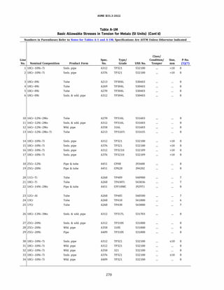
![ASME 831.3-2022
Table A-IM
Basic Allowable Stresses in Tension for Metals (SI Units) (Cont'd)
Numbers in Parentheses Refer to Notes for Tables A-1 and A-lM; Specifications Are ASTM Unless Otherwise Indicated
Basic Allowable Stress, S, MPa, at Metal
Temperature, °C
Min. [Notes (1), (2b), (3)]
Min. Min. Tensile Yield Max. Min.
Line Temp., Strength, Strength, Temp., Temp.
No. Notes °C (6) MPa MPa oc to 40 65 100 125 150 175 200
1 (28) -254 485 170 816 115 115 115 115 115 115 115
2 (28) (36) -254 485 170 816 115 115 115 115 115 115 115
3 (14) (36) -254 483 172 816 115 115 115 115 115 114 110
4 (14) (36) -254 483 172 816 115 115 115 115 115 114 110
5 (14) -254 483 172 816 115 115 115 115 115 114 110
6 ... -254 483 172 816 115 115 115 115 115 114 110
7 (36) -254 483 172 816 115 115 115 115 115 114 110
8 (14) (36) -254 483 172 816 115 115 115 115 115 113 109
9 (14) (36) -254 483 172 816 115 115 115 115 115 113 109
10 (14) -254 483 172 816 115 115 115 115 115 113 109
11 ... -254 483 172 816 115 115 115 115 115 113 109
12 (36) -254 483 172 816 115 115 115 115 115 113 109
13 (30) -254 517 207 816 138 138 138 138 138 138 134
14 (28) (30) -254 485 170 816 115 115 115 115 115 115 115
15 (28) (30) (36) -254 485 170 816 115 115 115 115 115 115 115
16 (30) -198 485 170 816 115 115 115 115 115 115 115
17 (30) (36) -198 485 170 816 115 115 115 115 115 115 115
18 (26) (28) (35) -198 448 193 816 129 129 129 129 127 125 124
19 (12) (28) (35) (39) -198 448 193 816 129 129 129 129 127 125 124
20 (35) -29 414 207 40 138
21 (35) (49) -29 414 276 40 138
22 (28) -198 483 207 40 138
23 (35) -29 414 207 538 138 138 138 137 135 134 133
24 (35) -29 414 207 649 138 138 138 137 135 134 133
25 (35) (49) -29 414 241 649 138 138 138 137 135 134 133
26 ... -198 517 207 454 138 138 138 138 138 136 131
27 (28) (35) -198 517 207 816 138 138 138 138 138 138 138
28 (28) (35) (36) -198 517 207 816 138 138 138 138 138 138 138
29 (28) (31) (35) (36) -198 517 207 816 138 138 138 138 138 138 138
30 (28) -254 515 205 816 138 138 138 138 138 138 138
31 (28) -254 515 205 816 138 138 138 138 138 138 138
32 (28) (36) -254 515 205 816 138 138 138 138 138 138 138
33 (28) (36) -254 515 205 816 138 138 138 138 138 138 138
34 (28) (36) -254 515 205 816 138 138 138 138 138 138 138
271](https://image.slidesharecdn.com/26162943-231229160810-282cb07a/85/ASME-B31-3-2022-Procces-piping-code-for-b31-3-298-320.jpg)
![ASME 831.3-2022
Table A-IM
Basic Allowable Stresses in Tension for Metals (SI Units) (Cont'd)
Numbers in Parentheses Refer to Notes for Tables A-1 and A-lM; Specifications Are ASTM Unless Otherwise Indicated
Basic Allowable Stress, S, MPa, at Metal Temperature, °C [Notes (1), (2b), (3)]
Line
No. 225 250 275 300 325 350 375 400 425 450 475 500 525
1 115 112 109 106 104 102 100 99.0 97.0 96.3 95.3 94.4 93.6
2 115 112 109 106 104 102 100 99.0 97.0 96.3 95.3 94.4 93.6
3 106 103 99.9 97.7 95.7 94.1 92.6 91.3 90.0 88.7 87.3 85.6 83.7
4 106 103 99.9 97.7 95.7 94.1 92.6 91.3 90.0 88.7 87.3 85.6 83.7
5 106 103 99.9 97.7 95.7 94.1 92.6 91.3 90.0 88.7 87.3 85.6 83.7
6 106 103 99.9 97.7 95.7 94.1 92.6 91.3 90.0 88.7 87.3 85.6 83.7
7 106 103 99.9 97.7 95.7 94.1 92.6 91.3 90.0 88.7 87.3 85.6 83.7
8 106 103 100 98.1 96.1 94.3 92.6 90.9 89.3 87.6 85.9 84.2 82.5
9 106 103 100 98.1 96.1 94.3 92.6 90.9 89.3 87.6 85.9 84.2 82.5
10 106 103 100 98.1 96.1 94.3 92.6 90.9 89.3 87.6 85.9 84.2 82.5
11 106 103 100 98.1 96.1 94.3 92.6 90.9 89.3 87.6 85.9 84.2 82.5
12 106 103 100 98.1 96.1 94.3 92.6 90.9 89.3 87.6 85.9 84.2 82.5
13 129 124 120 117 115 113 112 111 110 109 108 107 106
14 115 112 109 106 104 102 100 99.0 97.0 96.3 95.3 94.4 93.6
15 115 112 109 106 104 102 100 99.0 97.0 96.3 95.3 94.4 93.6
16 115 112 109 106 104 102 100 99.0 97.0 96.3 95.3 94.4 93.6
17 115 112 109 106 104 102 100 99.0 97.0 96.3 95.3 94.4 93.6
18 124 123 121 119 117 115 112 109 106 103 100 96.9 93.7
19 124 123 121 119 117 115 112 109 106 103 100 96.9 93.7
20
21
22
23 132 131 130 129 127 124 121 118 114 109 103 70.1 38.8
24 132 131 130 129 127 124 121 118 114 109 92.5 68.4 51.1
25 132 131 130 129 127 124 121 118 114 109 88.7 69.8 52.6
26 127 123 120 118 115 113 111 109 107 105 103
27 137 134 131 129 127 125 123 122 120 119 117 116 84.9
28 137 134 131 129 127 125 123 122 120 119 117 116 84.9
29 137 134 131 129 127 125 123 122 120 119 117 116 84.9
30 138 135 131 128 125 122 120 119 117 115 114 113 112
31 138 135 131 128 125 122 120 119 117 115 114 113 112
32 138 135 131 128 125 122 120 119 117 115 114 113 112
33 138 135 131 128 125 122 120 119 117 115 114 113 112
34 138 135 131 128 125 122 120 119 117 115 114 113 112
272](https://image.slidesharecdn.com/26162943-231229160810-282cb07a/85/ASME-B31-3-2022-Procces-piping-code-for-b31-3-299-320.jpg)
![ASME 831.3-2022
Table A-IM
Basic Allowable Stresses in Tension for Metals (SI Units) (Cont'd)
Numbers in Parentheses Refer to Notes for Tables A-1 and A-lM; Specifications Are ASTM Unless Otherwise Indicated
Basic Allowable Stress, S, MPa, at Metal Temperature, °C [Notes (1), (2b), (3)]
Line
No. 550 575 600 625 650 675 700 725 750 775 800 825
1 88.7 59.2 44.0 32.9 24.5 18.3 12.5 8.49 6.19 4.28 2.75 1.74
2 88.7 59.2 44.0 32.9 24.5 18.3 12.5 8.49 6.19 4.28 2.75 1.74
3 81.4 40.4 33.2 26.7 21.9 18.2 15.0 12.4 8.87 7.20 6.58 6.21
4 81.4 40.4 33.2 26.7 21.9 18.2 15.0 12.4 8.87 7.20 6.58 6.21
5 81.4 40.4 33.2 26.7 21.9 18.2 15.0 12.4 8.87 7.20 6.58 6.21
6 81.4 40.4 33.2 26.7 21.9 18.2 15.0 12.4 8.87 7.20 6.58 6.21
7 81.4 40.4 33.2 26.7 21.9 18.2 15.0 12.4 8.87 7.20 6.58 6.21
8 80.8 79.3 77.9 58.0 43.6 33.0 25.3 18.8 14.0 10.4 7.99 6.89
9 80.8 79.3 77.9 58.0 43.6 33.0 25.3 18.8 14.0 10.4 7.99 6.89
10 80.8 79.3 77.9 58.0 43.6 33.0 25.3 18.8 14.0 10.4 7.99 6.89
11 80.8 79.3 77.9 58.0 43.6 33.0 25.3 18.8 14.0 10.4 7.99 6.89
12 80.8 73.0 67.9 58.0 43.6 33.0 25.3 18.8 14.0 10.4 7.99 6.89
13 106 101 80.3 65.5 50.4 38.6 29.6 23.0 17.7 13.4 10.4 8.05
14 92.7 76.5 58.7 46.0 36.8 28.7 23.0 18.4 14.5 11.5 9.02 6.83
15 92.7 76.5 58.7 46.0 36.8 28.7 23.0 18.4 14.5 11.5 9.02 6.83
16 92.7 76.5 58.7 46.0 36.8 28.7 23.0 18.4 14.5 11.5 9.02 6.83
17 92.7 76.5 58.7 46.0 36.8 28.7 23.0 18.4 14.5 11.5 9.02 6.83
18 68.1 53.5 42.1 33.2 25.9 20.3 16.5 13.2 10.1 7.35 5.89 5.52
19 73.2 64.4 56.5 49.0 41.0 33.5 25.4 18.3 12.8 9.01 6.59 5.52
20
21
22
23 27.6
24 37.4 26.3 17.8 11.4 6.89
25 38.1 27.6 20.6 15.9 12.4
26
27 59.0 43.5 31.9 23.6 16.9 10.7 6.10 3.90 2.99 2.36 1.73 1.38
28 59.0 43.5 31.9 23.6 16.9 10.7 6.10 3.90 2.99 2.36 1.73 1.38
29 59.0 43.5 31.9 23.6 16.9 10.7 6.10 3.90 2.99 2.36 1.73 1.38
30 88.7 59.2 44.0 32.9 24.5 18.3 12.5 8.49 6.19 4.28 2.75 1.74
31 88.7 59.2 44.0 32.9 24.5 18.3 12.5 8.49 6.19 4.28 2.75 1.74
32 88.7 59.2 44.0 32.9 24.5 18.3 12.5 8.49 6.19 4.28 2.75 1.74
33 88.7 59.2 44.0 32.9 24.5 18.3 12.5 8.49 6.19 4.28 2.75 1.74
34 88.7 59.2 44.0 32.9 24.5 18.3 12.5 8.49 6.19 4.28 2.75 1.74
273](https://image.slidesharecdn.com/26162943-231229160810-282cb07a/85/ASME-B31-3-2022-Procces-piping-code-for-b31-3-300-320.jpg)
![ASME 831.3-2022
Table A-IM
Basic Allowable Stresses in Tension for Metals (SI Units) (Cont'd)
Numbers in Parentheses Refer to Notes for Tables A-1 and A-lM; Specifications Are ASTM Unless Otherwise Indicated
Basic Allowable Stress, S, MPa, at Metal
Temperature, °C
Min. [Notes (1), (2b), (3)]
Min. Min. Tensile Yield Max. Min.
Line Temp., Strength, Strength, Temp., Temp.
No. Notes °C (6) MPa MPa oc to 40 65 100 125 150 175 200
35 (28) (35) (39) -198 517 207 816 138 138 138 138 138 138 138
36 (28) (31) (35) (36) -198 517 207 816 138 138 138 138 138 138 138
37 (26) (28) -254 483 207 816 138 138 138 138 138 134 129
38 ... -254 517 207 816 138 138 138 138 138 138 138
39 (30) (36) -254 517 207 816 138 138 138 138 138 138 138
40 (30) (36) -254 517 207 816 138 138 138 138 138 138 138
41 (30) (36) -254 517 207 816 138 138 138 138 138 138 138
42 ... -198 517 207 816 138 138 138 138 138 138 138
43 (30) (36) -198 517 207 816 138 138 138 138 138 138 138
44 (30) (36) -198 517 207 816 138 138 138 138 138 138 138
45 (30) (36) -198 517 207 816 138 138 138 138 138 138 138
46 (12) (14) (28) (35) -198 483 207 816 138 138 138 138 137 135 134
(39)
47 (12) (14) (28) (35) -198 483 207 816 138 138 138 138 137 135 134
(39)
48 (29) (35) (39) -198 517 207 816 138 138 138 138 138 138 138
49 (28) -198 483 207 816 138 138 138 138 138 134 129
so (28) (30) -254 515 205 816 138 138 138 138 138 138 138
51 (28) (30) -254 515 205 816 138 138 138 138 138 138 138
52 (28) (30) (36) -254 515 205 816 138 138 138 138 138 138 138
53 (28) (30) (36) -254 515 205 816 138 138 138 138 138 138 138
54 (28) (30) (36) -254 515 205 816 138 138 138 138 138 138 138
55 (30) -198 515 205 816 138 138 138 138 138 138 138
56 (30) -198 515 205 816 138 138 138 138 138 138 138
57 (30) (36) -198 515 205 816 138 138 138 138 138 138 138
58 (30) (36) -198 515 205 816 138 138 138 138 138 138 138
59 (14) (26) (28) (31) -254 517 207 816 138 138 138 138 138 138 134
(36)
60 (14) (26) (28) (31) -254 517 207 816 138 138 138 138 138 138 134
(36)
61 (14) (26) (28) -254 517 207 816 138 138 138 138 138 138 134
62 (26) (28) -254 517 207 816 138 138 138 138 138 138 134
63 (26) (28) (31) (36) -254 517 207 816 138 138 138 138 138 138 134
64 (26) (28) (31) (36) -254 517 207 816 138 138 138 138 138 138 134
65 (26) (28) (31) (36) -254 517 207 816 138 138 138 138 138 138 134
66 (26) (28) -198 517 207 816 138 138 138 138 138 138 134
67 (26) (28) (31) (36) -198 517 207 816 138 138 138 138 138 138 134
275](https://image.slidesharecdn.com/26162943-231229160810-282cb07a/85/ASME-B31-3-2022-Procces-piping-code-for-b31-3-302-320.jpg)
![ASME 831.3-2022
Table A-IM
Basic Allowable Stresses in Tension for Metals (SI Units) (Cont'd)
Numbers in Parentheses Refer to Notes for Tables A-1 and A-lM; Specifications Are ASTM Unless Otherwise Indicated
Basic Allowable Stress, S, MPa, at Metal Temperature, °C [Notes (1), (2b), (3)]
Line
No. 225 250 275 300 325 350 375 400 425 450 475 500 525
35 138 135 133 131 129 127 125 124 122 121 119 117 108
36 138 135 133 131 129 127 125 124 122 121 119 117 108
37 125 122 119 116 113 111 109 107 105 103 101 99.1 94.4
38 138 138 137 135 132 130 128 127 126 126 125 125 125
39 138 138 137 135 132 130 128 127 126 126 125 125 125
40 138 138 137 135 132 130 128 127 126 126 125 125 125
41 138 138 137 135 132 130 128 127 126 126 125 125 125
42 138 138 137 135 132 130 128 127 126 126 125 125 125
43 138 138 137 135 132 130 128 127 126 126 125 125 125
44 138 138 137 135 132 130 128 127 126 126 125 125 125
45 138 138 137 135 132 130 128 127 126 126 125 125 125
46 133 131 129 128 125 123 120 117 114 111 107 104 100
47 133 131 129 128 125 123 120 117 114 111 107 104 100
48 137 134 131 129 127 125 123 122 120 119 117 116 108
49 125 122 119 116 113 111 109 107 105 103 101 99.1 97.3
so 138 135 131 128 125 122 120 119 117 115 114 113 112
51 138 135 131 128 125 122 120 119 117 115 114 113 112
52 138 135 131 128 125 122 120 119 117 115 114 113 112
53 138 135 131 128 125 122 120 119 117 115 114 113 112
54 138 135 131 128 125 122 120 119 117 115 114 113 112
55 138 135 131 128 125 122 120 119 117 115 114 113 112
56 138 135 131 128 125 122 120 119 117 115 114 113 112
57 138 135 131 128 125 122 120 119 117 115 114 113 112
58 138 135 131 128 125 122 120 119 117 115 114 113 112
59 129 125 122 119 116 114 112 111 110 109 108 107 106
60 129 125 122 119 116 114 112 111 110 109 108 107 106
61 129 125 122 119 116 114 112 111 110 109 108 107 106
62 129 125 122 119 116 114 112 111 110 109 108 107 106
63 129 125 122 119 116 114 112 111 110 109 108 107 106
64 129 125 122 119 116 114 112 111 110 109 108 107 106
65 129 125 122 119 116 114 112 111 110 109 108 107 106
66 129 125 122 119 116 114 112 111 110 109 108 107 106
67 129 125 122 119 116 114 112 111 110 109 108 107 106
276](https://image.slidesharecdn.com/26162943-231229160810-282cb07a/85/ASME-B31-3-2022-Procces-piping-code-for-b31-3-303-320.jpg)
![ASME 831.3-2022
Table A-IM
Basic Allowable Stresses in Tension for Metals (SI Units) (Cont'd)
Numbers in Parentheses Refer to Notes for Tables A-1 and A-lM; Specifications Are ASTM Unless Otherwise Indicated
Basic Allowable Stress, S, MPa, at Metal Temperature, °C [Notes (1), (2b), (3)]
Line
No. 550 575 600 625 650 675 700 725 750 775 800 825
35 83.7 64.0 48.5 36.3 27.3 21.0 15.9 12.5 9.87 7.65 5.97 5.17
36 83.7 64.0 48.5 36.3 27.3 21.0 15.9 12.5 9.87 7.65 5.97 5.17
37 75.3 60.4 49.0 40.1 32.8 27.2 23.4 19.6 16.8 14.7 12.8 11.7
38 97.6 75.9 57.2 40.2 30.3 23.2 16.2 11.4 8.97 7.08 5.89 5.52
39 97.6 75.9 57.2 40.2 30.3 23.2 16.2 11.4 8.97 7.08 5.89 5.52
40 97.6 75.9 57.2 40.2 30.3 23.2 16.2 11.4 8.97 7.08 5.89 5.52
41 97.6 75.9 57.2 40.2 30.3 23.2 16.2 11.4 8.97 7.08 5.89 5.52
42 97.6 75.9 57.2 40.2 30.3 23.2 16.2 11.4 8.97 7.08 5.89 5.52
43 97.6 75.9 57.2 40.2 30.3 23.2 16.2 11.4 8.97 7.08 5.89 5.52
44 97.6 75.9 57.2 40.2 30.3 23.2 16.2 11.4 8.97 7.08 5.89 5.52
45 97.6 75.9 57.2 40.2 30.3 23.2 16.2 11.4 8.97 7.08 5.89 5.52
46 68.1 53.5 42.1 33.2 25.9 20.3 16.5 13.2 10.1 7.35 5.89 5.52
47 68.1 53.5 42.1 33.2 25.9 20.3 16.5 13.2 10.1 7.35 5.89 5.52
48 83.7 64.0 48.5 36.3 27.3 21.0 15.9 12.5 9.87 7.65 5.97 5.17
49 95.5 75.9 57.2 40.2 30.3 23.2 16.2 11.4 8.97 7.08 5.89 5.52
so 100 76.5 58.7 46.0 36.8 28.7 23.0 18.4 14.5 11.5 9.02 6.83
51 100 76.5 58.7 46.0 36.8 28.7 23.0 18.4 14.5 11.5 9.02 6.83
52 100 76.5 58.7 46.0 36.8 28.7 23.0 18.4 14.5 11.5 9.02 6.83
53 100 76.5 58.7 46.0 36.8 28.7 23.0 18.4 14.5 11.5 9.02 6.83
54 100 76.5 58.7 46.0 36.8 28.7 23.0 18.4 14.5 11.5 9.02 6.83
55 100 76.5 58.7 46.0 36.8 28.7 23.0 18.4 14.5 11.5 9.02 6.83
56 100 76.5 58.7 46.0 36.8 28.7 23.0 18.4 14.5 11.5 9.02 6.83
57 100 76.5 58.7 46.0 36.8 28.7 23.0 18.4 14.5 11.5 9.02 6.83
58 100 76.5 58.7 46.0 36.8 28.7 23.0 18.4 14.5 11.5 9.02 6.83
59 105 97.8 80.8 65.0 50.4 38.6 29.6 23.0 17.4 13.3 10.4 8.96
60 105 97.8 80.8 65.0 50.4 38.6 29.6 23.0 17.4 13.3 10.4 8.96
61 105 97.8 80.8 65.0 50.4 38.6 29.6 23.0 17.4 13.3 10.4 8.96
62 105 97.8 80.8 65.0 50.4 38.6 29.6 23.0 17.4 13.3 10.4 8.96
63 105 97.8 80.8 65.0 50.4 38.6 29.6 23.0 17.4 13.3 10.4 8.96
64 105 97.8 80.8 65.0 50.4 38.6 29.6 23.0 17.4 13.3 10.4 8.96
65 105 97.8 80.8 65.0 50.4 38.6 29.6 23.0 17.4 13.3 10.4 8.96
66 105 97.8 80.8 65.0 50.4 38.6 29.6 23.0 17.4 13.3 10.4 8.96
67 105 97.8 80.8 65.0 50.4 38.6 29.6 23.0 17.4 13.3 10.4 8.96
277](https://image.slidesharecdn.com/26162943-231229160810-282cb07a/85/ASME-B31-3-2022-Procces-piping-code-for-b31-3-304-320.jpg)
![ASME 831.3-2022
Table A-IM
Basic Allowable Stresses in Tension for Metals (SI Units) (Cont'd)
Numbers in Parentheses Refer to Notes for Tables A-1 and A-lM; Specifications Are ASTM Unless Otherwise Indicated
Basic Allowable Stress, S, MPa, at Metal
Temperature, °C
Min. [Notes (1), (2b), (3)]
Min. Min. Tensile Yield Max. Min.
Line Temp., Strength, Strength, Temp., Temp.
No. Notes °C (6) MPa MPa oc to 40 65 100 125 150 175 200
68 (26) (31) (36) -198 517 207 816 138 138 138 138 138 138 134
69 (26) -198 517 207 816 138 138 138 138 138 138 134
70 (30) (36) -198 517 207 816 138 138 138 138 138 138 138
71 (28) -254 517 207 816 138 138 138 138 138 138 138
72 (28) (30) (36) -254 517 207 816 138 138 138 138 138 138 138
73 (28) (30) (36) -254 517 207 816 138 138 138 138 138 138 138
74 (28) (30) (36) -254 517 207 816 138 138 138 138 138 138 138
75 (28) -198 517 207 816 138 138 138 138 138 138 138
76 (28) (30) (36) -198 517 207 816 138 138 138 138 138 138 138
77 (28) (30) (36) -198 517 207 816 138 138 138 138 138 138 138
78 (28) (30) (36) -198 517 207 816 138 138 138 138 138 138 138
79 ... -198 517 207 816 138 138 138 138 138 138 138
80 ... -198 517 207 816 138 138 138 138 138 138 138
81 (14) (26) (28) (31) -254 517 207 816 138 138 138 138 138 134 129
(36)
82 (14) (26) (28) (31) -254 517 207 816 138 138 138 138 138 134 129
(36)
83 (14) (26) (28) -254 517 207 816 138 138 138 138 138 134 129
84 (26) (28) -254 517 207 816 138 138 138 138 138 134 129
85 (26) (28) (31) (36) -254 517 207 816 138 138 138 138 138 134 129
86 (20) (26) (28) (31) -254 517 207 816 138 138 138 138 138 134 129
(36)
87 (26) (31) (36) -198 517 207 816 138 138 138 138 138 134 129
88 (26) (28) (31) (36) -254 517 207 816 138 138 138 138 138 134 129
89 (26) -198 517 207 816 138 138 138 138 138 134 129
90 (26) (28) -254 483 207 816 138 138 138 138 130 124 118
91 (26) -198 490 220 260 143 143 143 143 141 135 130
92 (26) -198 490 220 260 143 143 143 143 141 135 130
93 (35) -29 483 276 538 161 161 161 161 161 161 161
94 (35) -29 483 276 538 161 161 161 158 155 153 152
95 ... -29 485 350 316 162 162 162 162 162 161 159
96 (35) (39) -198 552 276 482 184 184 184 184 184 184 184
97 (25) -51 600 400 316 200 200 191 185 180 175 171
98 (25) -51 600 400 316 200 200 191 185 180 175 171
99 (25) -51 600 400 316 200 200 191 185 180 175 171
279](https://image.slidesharecdn.com/26162943-231229160810-282cb07a/85/ASME-B31-3-2022-Procces-piping-code-for-b31-3-306-320.jpg)
![ASME 831.3-2022
Table A-IM
Basic Allowable Stresses in Tension for Metals (SI Units) (Cont'd)
Numbers in Parentheses Refer to Notes for Tables A-1 and A-lM; Specifications Are ASTM Unless Otherwise Indicated
Basic Allowable Stress, S, MPa, at Metal Temperature, °C [Notes (1), (2b), (3)]
Line
No. 225 250 275 300 325 350 375 400 425 450 475 500 525
68 129 125 122 119 116 114 112 111 110 109 108 107 106
69 129 125 122 119 116 114 112 111 110 109 108 107 106
70 138 138 137 135 132 130 129 127 126 126 125 125 125
71 138 138 137 135 132 130 129 127 126 126 125 125 125
72 138 138 137 135 132 130 128 127 126 126 125 125 125
73 138 138 137 135 132 130 128 127 126 126 125 125 125
74 138 138 137 135 132 130 128 127 126 126 125 125 125
75 138 138 137 135 132 130 128 127 126 126 125 125 125
76 138 138 137 135 132 130 128 127 126 126 125 125 125
77 138 138 137 135 132 130 128 127 126 126 125 125 125
78 138 138 137 135 132 130 128 127 126 126 125 125 125
79 138 138 137 135 132 130 129 127 126 126 125 125 125
80 138 138 137 135 132 130 129 127 126 126 125 125 125
81 125 122 119 116 113 111 109 107 105 103 101 99.1 97.3
82 125 122 119 116 113 111 109 107 105 103 101 99.1 97.3
83 125 122 119 116 113 111 109 107 105 103 101 99.1 97.3
84 125 122 119 116 113 111 109 107 105 103 101 99.1 97.3
85 125 122 119 116 113 111 109 107 105 103 101 99.1 97.3
86 125 122 119 116 113 111 109 107 105 103 101 99.1 97.3
87 125 122 119 116 113 111 109 107 105 103 101 99.1 97.3
88 125 122 119 116 113 111 109 107 105 103 101 99.1 97.3
89 125 122 119 116 113 111 109 107 105 103 101 99.1 97.3
90 114 110 107 104 102 101 99.3 98.1 97.0 95.9 94.7 93.3 91.5
91 125 120 116
92 125 120 116
93 161 161 161 161 161 97.0 84.3 73.3 64.0 55.8 43.9 31.7 21.4
94 150 149 147 145 144 141 139 136 132 128 122 116 109
95 156 154 152 149 146
96 184 184 184 184 184 184 184 184 184 184 184 184
97 166 161 153 143 111
98 166 161 153 143 111
99 166 161 153 143 111
280](https://image.slidesharecdn.com/26162943-231229160810-282cb07a/85/ASME-B31-3-2022-Procces-piping-code-for-b31-3-307-320.jpg)
![ASME 831.3-2022
Table A-IM
Basic Allowable Stresses in Tension for Metals (SI Units) (Cont'd)
Numbers in Parentheses Refer to Notes for Tables A-1 and A-lM; Specifications Are ASTM Unless Otherwise Indicated
Basic Allowable Stress, S, MPa, at Metal Temperature, °C [Notes (1), (2b), (3)]
Line
No. 550 575 600 625 650 675 700 725 750 775 800 825
68 105 97.8 80.8 65.0 50.4 38.6 29.6 23.0 17.4 13.3 10.4 8.96
69 105 97.8 80.8 65.0 50.4 38.6 29.6 23.0 17.4 13.3 10.4 8.96
70 125 112 90.6 69.6 53.8 41.4 31.8 24.0 18.8 14.6 10.9 8.96
71 125 112 90.6 69.6 53.8 41.4 31.8 24.0 18.8 14.6 10.9 8.96
72 125 112 90.6 69.6 53.8 41.4 31.8 24.0 18.8 14.6 10.9 8.96
73 125 112 90.6 69.6 53.8 41.4 31.8 24.0 18.8 14.6 10.9 8.96
74 125 112 90.6 69.6 53.8 41.4 31.8 24.0 18.8 14.6 10.9 8.96
75 125 112 90.6 69.6 53.8 41.4 31.8 24.0 18.8 14.6 10.9 8.96
76 125 112 90.6 69.6 53.8 41.4 31.8 24.0 18.8 14.6 10.9 8.96
77 125 112 90.6 69.6 53.8 41.4 31.8 24.0 18.8 14.6 10.9 8.96
78 125 112 90.6 69.6 53.8 41.4 31.8 24.0 18.8 14.6 10.9 8.96
79 125 112 90.6 69.6 53.8 41.4 31.8 24.0 18.8 14.6 10.9 8.96
80 125 112 90.6 69.6 53.8 41.4 31.8 24.0 18.8 14.6 10.9 8.96
81 95.5 78.9 63.8 51.6 41.6 32.9 26.5 21.3 17.2 14.1 11.2 9.65
82 95.5 78.9 63.8 51.6 41.6 32.9 26.5 21.3 17.2 14.1 11.2 9.65
83 95.5 78.9 63.8 51.6 41.6 32.9 26.5 21.3 17.2 14.1 11.2 9.65
84 95.5 78.9 63.8 51.6 41.6 32.9 26.5 21.3 17.2 14.1 11.2 9.65
85 95.5 78.9 63.8 51.6 41.6 32.9 26.5 21.3 17.2 14.1 11.2 9.65
86 95.5 78.9 63.8 51.6 41.6 32.9 26.5 21.3 17.2 14.1 11.2 9.65
87 95.5 78.9 63.8 51.6 41.6 32.9 26.5 21.3 17.2 14.1 11.2 9.65
88 95.5 78.9 63.8 51.6 41.6 32.9 26.5 21.3 17.2 14.1 11.2 9.65
89 95.5 78.9 63.8 51.6 41.6 32.9 26.5 21.3 17.2 14.1 11.2 9.65
90 89.1 72.7 57.7 46.0 36.9 30.1 24.3 20.3 17.0 14.3 12.1 11.0
91
92
93 17.2
94 104
95
96
97
98
99
281](https://image.slidesharecdn.com/26162943-231229160810-282cb07a/85/ASME-B31-3-2022-Procces-piping-code-for-b31-3-308-320.jpg)
![ASME 831.3-2022
Table A-IM
Basic Allowable Stresses in Tension for Metals (SI Units) (Cont'd)
Numbers in Parentheses Refer to Notes for Tables A-1 and A-lM; Specifications Are ASTM Unless Otherwise Indicated
Basic Allowable Stress, S, MPa, at Metal
Temperature, °C
Min. [Notes (1), (2b), (3)]
Min. Min. Tensile Yield Max. Min.
Line Temp., Strength, Strength, Temp., Temp.
No. Notes °C (6) MPa MPa oc to 40 65 100 125 150 175 200
100 ... -198 650 300 454 202 202 202 202 199 192 185
101 ... -198 650 300 454 202 202 202 202 199 192 185
102 (35) -29 621 448 40 207
103 ... -198 655 310 475 207 207 207 207 203 196 189
104 ... -198 690 310 475 207 207 207 207 203 196 189
105 (25) -51 621 448 316 207 207 207 204 199 196 193
106 (25) -51 621 448 316 207 207 207 204 199 196 193
107 (25) -51 621 448 316 207 207 207 204 199 196 193
108 ... -198 655 310 454 207 206 187 177 170 165 162
109 (36) -198 655 310 454 207 206 187 177 170 165 162
110 ... -198 655 310 454 207 207 207 207 203 196 190
111 ... -198 675 310 454 207 207 207 207 203 196 190
112 ... -198 655 310 454 207 207 207 207 203 196 190
113 ... -198 675 310 454 207 207 207 207 203 196 190
114 (25) -29 621 483 40 207
115 (26) -198 655 310 427 207 207 207 207 206 202 198
116 (26) -198 655 310 427 207 207 207 207 206 202 198
117 (26) -198 655 310 427 207 207 207 207 206 202 198
118 (26) -198 655 310 427 207 207 207 207 206 202 198
119 (26) -198 690 310 427 207 207 207 207 207 207 205
120 (26) -198 690 310 427 207 207 207 207 207 207 205
121 (26) -198 690 310 427 207 207 207 207 207 207 205
122 (26) -198 690 310 427 207 207 207 207 207 207 205
123 (25) -29 650 450 316 217 217 215 211 206 203 199
124 (25) -29 650 450 316 217 217 215 211 206 203 199
125 (25) -51 655 450 316 218 218 218 215 210 206 203
126 (25) -51 655 485 316 218 218 218 215 210 206 203
127 (25) -51 680 480 316 227 227 227 227 227 227 227
128 (25) -51 680 480 316 227 227 227 227 227 227 227
129 (25) -29 700 530 316 233 233 231 227 222 219 215
130 (25) -29 700 530 316 233 233 231 227 222 219 215
283](https://image.slidesharecdn.com/26162943-231229160810-282cb07a/85/ASME-B31-3-2022-Procces-piping-code-for-b31-3-310-320.jpg)
![ASME 831.3-2022
Table A-IM
Basic Allowable Stresses in Tension for Metals (SI Units) (Cont'd)
Numbers in Parentheses Refer to Notes for Tables A-1 and A-lM; Specifications Are ASTM Unless Otherwise Indicated
Basic Allowable Stress, S, MPa, at Metal Temperature, °C [Notes (1), (2b), (3)]
Line
No. 225 250 275 300 325 350 375 400 425 450 475 500 525
100 180 175 171 168 165 164 162 161 160 159 158
101 180 175 171 168 165 164 162 161 160 159 158
102
103 184 179 175 172 169 167 165 165 164 163 161
104 184 179 175 172 169 167 165 165 164 163 161
105 190 188 187 186 185
106 190 188 187 186 185
107 190 188 187 186 185
108 160 159 158 158 158 157 156 154 152 149 146
109 160 159 158 158 158 157 156 154 152 149 146
110 184 179 175 172 169 167 166 165 164 163 161
111 184 179 175 172 169 167 166 165 164 163 161
112 184 179 175 172 169 167 166 165 164 163 161
113 184 179 175 172 169 167 166 165 164 163 161
114
115 195 192 188 184 179 176 173 170 167 166
116 195 192 188 184 179 176 173 170 167 166
117 195 192 188 184 179 176 173 170 167 166
118 195 192 188 184 179 176 173 170 167 166
119 199 194 188 184 179 176 173 170 167 166
120 199 194 188 184 179 176 173 170 167 166
121 199 194 188 184 179 176 173 170 167 166
122 199 194 188 184 179 176 173 170 167 166
123 199 199 199 199 199
124 199 199 199 199 199
125 201 199 197 196 196
126 201 199 197 196 196
127 227 227 227 227 227
128 227 227 227 227 227
129 214 214 214 214 214
130 214 214 214 214 214
284](https://image.slidesharecdn.com/26162943-231229160810-282cb07a/85/ASME-B31-3-2022-Procces-piping-code-for-b31-3-311-320.jpg)
![ASME 831.3-2022
Table A-IM
Basic Allowable Stresses in Tension for Metals (SI Units) (Cont'd)
Numbers in Parentheses Refer to Notes for Tables A-1 and A-lM; Specifications Are ASTM Unless Otherwise Indicated
Basic Allowable Stress, S, MPa, at Metal Temperature, °C [Notes (1), (2b), (3)]
Line
No. 550 575 600 625 650 675 700 725 750 775 800 825
100
101
102
103
104
105
106
107
108
109
110
111
112
113
114
115
116
117
118
119
120
121
122
123
124
125
126
127
128
129
130
285](https://image.slidesharecdn.com/26162943-231229160810-282cb07a/85/ASME-B31-3-2022-Procces-piping-code-for-b31-3-312-320.jpg)
![ASME 831.3-2022
Table A-IM
Basic Allowable Stresses in Tension for Metals (SI Units) (Cont'd)
Numbers in Parentheses Refer to Notes for Tables A-1 and A-lM; Specifications Are ASTM Unless Otherwise Indicated
Basic Allowable Stress, S, MPa, at Metal
Temperature, °C
Min. [Notes (1), (2b), (3)]
Min. Min. Tensile Yield Max. Min.
Line Temp., Strength, Strength, Temp., Temp.
No. Notes °C (6) MPa MPa oc to 40 65 100 125 150 175 200
131 (25) -51 655 450 343 218 218 210 203 199 197 197
132 (25) -51 655 450 343 218 218 210 203 199 197 197
133 (25) -51 655 450 343 218 218 210 203 199 197 197
134 (25) -51 655 450 316 218 218 218 215 210 206 203
135 (25) -51 690 485 343 230 230 221 214 209 207 207
136 (25) -51 690 485 343 230 230 221 214 209 207 207
137 (25) -51 690 485 343 230 230 221 214 209 207 207
138 (25) -51 740 540 316 247 247 247 247 247 247 247
139 (25) -51 740 540 316 247 247 247 247 247 247 247
140 (25) -51 750 550 316 250 250 248 243 238 236 234
141 (25) -51 750 550 316 250 250 248 243 238 236 234
142 (25) -51 750 550 316 251 251 249 243 238 235 231
143 (25) -51 750 550 316 251 251 249 243 238 235 231
144 (36) -198 795 415 427 264 264 260 253 247 242 238
145 (25) -51 800 550 316 267 265 264 257 251 247 243
146 (25) -51 800 550 316 267 265 264 257 251 247 243
147 (25) -51 800 552 316 267 265 264 257 251 247 243
148 (25) -51 800 650 316 267 267 265 259 253 250 246
149 (25) -51 800 650 316 267 267 265 259 253 250 246
150 (26) (36) (39) -198 483 172 40 115
151 (35) -29 414 172 538 115 109 105 103 102 101 100
152 (36) -254 483 172 816 115 115 115 115 115 114 110
153 (36) -254 483 172 816 115 115 115 115 115 113 109
154 (26) (36) -198 517 207 538 138 138 138 138 138 134 129
155 ... -29 455 275 316 152 152 152 152 152 151 149
156 ... -29 485 350 316 162 162 162 162 162 161 159
157 (35) (50) -29 414 207 649 138 130 126 124 122 121 120
158 (35) -29 448 207 649 138 130 126 124 122 121 120
159 (35) -29 448 207 649 138 130 126 124 122 121 120
160 (35) -29 448 207 649 138 130 126 124 122 121 120
161 (36) -198 517 207 454 138 138 138 138 138 136 131
287](https://image.slidesharecdn.com/26162943-231229160810-282cb07a/85/ASME-B31-3-2022-Procces-piping-code-for-b31-3-314-320.jpg)
![ASME 831.3-2022
Table A-IM
Basic Allowable Stresses in Tension for Metals (SI Units) (Cont'd)
Numbers in Parentheses Refer to Notes for Tables A-1 and A-lM; Specifications Are ASTM Unless Otherwise Indicated
Basic Allowable Stress, S, MPa, at Metal Temperature, °C [Notes (1), (2b), (3)]
Line
No. 225 250 275 300 325 350 375 400 425 450 475 500 525
131 197 197 197 197 197 197
132 197 197 197 197 197 197
133 197 197 197 197 197 197
134 201 199 197 196 196
135 207 207 207 207 207 207
136 207 207 207 207 207 207
137 207 207 207 207 207 207
138 247 247 247 247 247
139 247 247 247 247 247
140 233 233 233 233 233
141 233 233 233 233 233
142 230 228 228 228 228
143 230 228 228 228 228
144 235 234 232 231 229 228 226 223 221 218
145 241 238 237 237 236
146 241 238 237 237 236
147 241 238 237 237 236
148 245 243 243 242 242
149 245 243 243 242 242
150
151 99.7 99.1 98.4 97.5 96.2 94.7 92.6 90.1 87.0 83.4 79.2 70.1 38.8
152 106 103 99.9 97.7 95.7 94.1 92.6 91.3 90.0 88.7 87.3 85.6 83.7
153 106 103 100 98.1 96.1 94.3 92.6 90.9 89.3 87.6 85.9 84.2 82.5
154 125 122 119 116 113 111 109 107 105 103 101 99.1 97.3
155 147 145 142 140 137
156 156 154 152 149 146
157 120 119 118 117 115 114 111 108 104 100 92.5 68.4 51.1
158 120 119 118 117 115 114 111 108 104 100 92.5 68.4 51.1
159 120 119 118 117 115 114 111 108 104 100 88.7 69.8 52.6
160 120 119 118 117 115 114 111 108 104 100 88.7 69.8 52.6
161 127 123 120 118 115 113 111 109 107 105 103
288](https://image.slidesharecdn.com/26162943-231229160810-282cb07a/85/ASME-B31-3-2022-Procces-piping-code-for-b31-3-315-320.jpg)
![ASME 831.3-2022
Table A-IM
Basic Allowable Stresses in Tension for Metals (SI Units) (Cont'd)
Numbers in Parentheses Refer to Notes for Tables A-1 and A-lM; Specifications Are ASTM Unless Otherwise Indicated
Basic Allowable Stress, S, MPa, at Metal Temperature, °C [Notes (1), (2b), (3)]
Line
No. 550 575 600 625 650 675 700 725 750 775 800 825
131
132
133
134
135
136
137
138
139
140
141
142
143
144
145
146
147
148
149
150
151 27.6
152 81.4 40.4 33.2 26.7 21.9 18.2 15.0 12.4 8.87 7.20 6.58 6.21
153 80.8 73.0 67.9 58.0 43.6 33.0 25.3 18.8 14.0 10.4 7.99 6.89
154 96.4
155
156
157 37.4 26.3 17.8 11.4 6.89
158 37.4 26.3 17.8 11.4 6.89
159 38.1 27.6 20.6 15.9 12.4
160 38.1 27.6 20.6 15.9 12.4
161
289](https://image.slidesharecdn.com/26162943-231229160810-282cb07a/85/ASME-B31-3-2022-Procces-piping-code-for-b31-3-316-320.jpg)
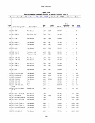
![ASME 831.3-2022
Table A-IM
Basic Allowable Stresses in Tension for Metals (SI Units) (Cont'd)
Numbers in Parentheses Refer to Notes for Tables A-1 and A-lM; Specifications Are ASTM Unless Otherwise Indicated
Basic Allowable Stress, S, MPa, at Metal
Temperature, °C
Min. [Notes (1), (2b), (3)]
Min. Min. Tensile Yield Max. Min.
Line Temp., Strength, Strength, Temp., Temp.
No. Notes °C (6) MPa MPa oc to 40 65 100 125 150 175 200
162 (28) (31) (35) (36) -198 517 207 816 138 138 138 138 138 138 138
163 (28) (31) (36) -198 515 205 816 138 138 138 138 138 138 138
164 (28) (35) (36) -198 517 207 816 138 138 138 138 138 138 138
165 (36) -254 517 207 816 138 138 138 138 138 138 138
166 (36) -198 517 207 816 138 138 138 138 138 138 138
167 (29) (35) (39) -198 517 207 816 138 138 138 138 138 138 138
168 (28) (30) (36) -198 515 205 816 138 138 138 138 138 138 138
169 (30) (36) -198 515 205 816 138 138 138 138 138 138 138
170 (26) (28) (36) -254 517 207 816 138 138 138 138 138 138 134
171 (26) (28) (36) -198 517 207 816 138 138 138 138 138 138 134
172 (28) (36) -254 517 207 816 138 138 138 138 138 138 138
173 (28) (36) -198 517 207 816 138 138 138 138 138 138 138
174 (26) (28) (36) -254 517 207 816 138 138 138 138 138 134 129
175 (26) -198 490 220 260 143 143 143 143 141 135 130
176 (25) -51 600 400 316 200 200 191 185 180 175 171
177 (25) -51 620 450 316 207 207 207 204 199 196 193
178 ... -198 655 310 454 207 206 187 177 170 165 162
179 ... -254 655 310 454 207 207 207 207 203 196 190
180 ... -254 690 310 454 207 207 207 207 203 196 190
181 (26) -198 655 310 427 207 207 207 207 206 202 198
182 (26) -198 690 310 427 207 207 207 207 207 207 205
183 (25) -29 650 450 316 217 217 217 211 206 203 199
184 (25) -51 655 450 316 218 218 218 215 210 206 203
185 (25) -51 680 480 316 227 227 227 227 227 227 227
186 (25) -29 700 530 316 233 233 231 227 222 219 215
187 (25) -51 655 450 343 218 218 210 203 199 197 197
188 (25) -51 690 485 343 230 230 221 214 209 207 207
189 (25) -51 740 540 316 247 247 247 247 247 247 247
190 (25) -51 750 550 316 251 251 249 243 238 235 231
291](https://image.slidesharecdn.com/26162943-231229160810-282cb07a/85/ASME-B31-3-2022-Procces-piping-code-for-b31-3-318-320.jpg)
![ASME 831.3-2022
Table A-IM
Basic Allowable Stresses in Tension for Metals (SI Units) (Cont'd)
Numbers in Parentheses Refer to Notes for Tables A-1 and A-lM; Specifications Are ASTM Unless Otherwise Indicated
Basic Allowable Stress, S, MPa, at Metal Temperature, °C [Notes (1), (2b), (3)]
Line
No. 225 250 275 300 325 350 375 400 425 450 475 500 525
162 137 134 131 129 127 125 123 122 120 119 117 116 84.9
163 138 135 131 128 125 122 120 119 117 115 114 113 112
164 138 135 133 131 129 127 125 124 122 121 119 117 108
165 138 138 137 135 132 130 128 127 126 126 125 125 125
166 138 138 137 135 132 130 128 127 126 126 125 125 125
167 137 134 131 129 127 125 123 122 120 119 117 116 108
168 138 135 131 128 125 122 120 119 117 115 114 113 112
169 138 135 131 128 125 122 120 119 117 115 114 113 112
170 129 125 122 119 116 114 112 111 110 109 108 107 106
171 129 125 122 119 116 114 112 111 110 109 108 107 106
172 138 138 137 135 132 130 128 127 126 126 125 125 125
173 138 138 137 135 132 130 128 127 126 126 125 125 125
174 125 122 119 116 113 111 109 107 105 103 101 99.1 97.3
175 125 120 116
176 166 161 153 143 111
177 190 188 187 186 185
178 160 159 158 158 158 157 156 154 152 149 146
179 184 179 175 172 169 167 166 165 164 163 161
180 184 179 175 172 169 167 166 165 164 163 161
181 195 192 188 184 179 176 173 170 167 166
182 199 194 188 184 179 176 173 170 167 166
183 199 199 199 199 199
184 201 199 197 196 196
185 227 227 227 227 227
186 214 214 214 214 214
187 197 197 197 197 197 197
188 207 207 207 207 207 207
189 247 247 247 247 247
190 230 228 228 228 228
292](https://image.slidesharecdn.com/26162943-231229160810-282cb07a/85/ASME-B31-3-2022-Procces-piping-code-for-b31-3-319-320.jpg)
![ASME 831.3-2022
Table A-IM
Basic Allowable Stresses in Tension for Metals (SI Units) (Cont'd)
Numbers in Parentheses Refer to Notes for Tables A-1 and A-lM; Specifications Are ASTM Unless Otherwise Indicated
Basic Allowable Stress, S, MPa, at Metal Temperature, °C [Notes (1), (2b), (3)]
Line
No. 550 575 600 625 650 675 700 725 750 775 800 825
162 59.0 43.5 31.9 23.6 16.9 10.7 6.10 3.90 2.99 2.36 1.73 1.38
163 88.7 59.2 44.0 32.9 24.5 18.3 12.5 8.49 6.19 4.28 2.75 1.74
164 83.7 64.0 48.5 36.3 27.3 21.0 15.9 12.5 9.87 7.65 5.97 5.17
165 97.6 75.9 57.2 40.2 30.3 23.2 16.2 11.4 8.97 7.08 5.89 5.52
166 97.6 75.9 57.2 40.2 30.3 23.2 16.2 11.4 8.97 7.08 5.89 5.52
167 83.7 64.0 48.5 36.3 27.3 21.0 15.9 12.5 9.87 7.65 5.97 5.17
168 100 76.5 58.7 46.0 36.8 28.7 23.0 18.4 14.5 11.5 9.02 6.83
169 100 76.5 58.7 46.0 36.8 28.7 23.0 18.4 14.5 11.5 9.02 6.83
170 105 97.8 80.8 65.0 50.4 38.6 29.6 23.0 17.4 13.3 10.4 8.96
171 105 97.8 80.8 65.0 50.4 38.6 29.6 23.0 17.4 13.3 10.4 8.96
172 125 112 90.6 69.6 53.8 41.4 31.8 24.0 18.8 14.6 10.9 8.96
173 125 112 90.6 69.6 53.8 41.4 31.8 24.0 18.8 14.6 10.9 8.96
174 95.5 78.9 63.8 51.6 41.6 32.9 26.5 21.3 17.2 14.1 11.2 9.65
175
176
177
178
179
180
181
182
183
184
185
186
187
188
189
190
293](https://image.slidesharecdn.com/26162943-231229160810-282cb07a/85/ASME-B31-3-2022-Procces-piping-code-for-b31-3-320-320.jpg)
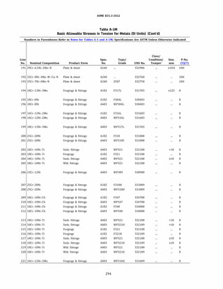
![ASME 831.3-2022
Table A-IM
Basic Allowable Stresses in Tension for Metals (SI Units) (Cont'd)
Numbers in Parentheses Refer to Notes for Tables A-1 and A-lM; Specifications Are ASTM Unless Otherwise Indicated
Basic Allowable Stress, S, MPa, at Metal
Temperature, °C
Min. [Notes (1), (2b), (3)]
Min. Min. Tensile Yield Max. Min.
Line Temp., Strength, Strength, Temp., Temp.
No. Notes °C (6) MPa MPa oc to 40 65 100 125 150 175 200
191 (25) -51 800 650 316 267 267 265 259 253 250 246
192 (25) -51 750 550 316 250 250 248 243 238 236 234
193 (25) -51 800 550 316 267 265 264 257 251 247 243
194 (9) (23) -198 483 172 454 115 115 115 115 115 113 109
195 (9) (23) -254 483 172 816 115 115 115 115 115 114 110
196 (32) (37) -254 483 172 816 115 115 115 115 115 114 110
197 (9) (23) -254 483 172 816 115 115 115 115 115 113 109
198 (32) (37) -254 483 172 816 115 115 115 115 115 113 109
199 (32) (37) -198 517 207 454 138 138 138 138 138 136 131
200 (9) (35) (39) -198 517 207 816 138 138 138 138 138 138 138
201 (28) (32) (35) (37) -198 517 207 816 138 138 138 138 138 138 138
202 (28) -198 485 170 816 115 115 115 115 115 115 115
203 (9) (21) (28) -198 515 205 816 138 138 138 138 138 138 138
204 (28) -198 515 205 816 138 138 138 138 138 138 138
205 (28) -198 515 205 816 138 138 138 138 138 138 138
206 (28) (32) (35) (37) -198 517 207 816 138 138 138 138 138 138 138
(39)
207 (9) (21) (29) (35) (39) -198 517 207 816 138 138 138 138 138 138 138
208 (29) (32) (35) (37) -198 517 207 816 138 138 138 138 138 138 138
(39)
209 (9) (21) -254 517 207 816 138 138 138 138 138 138 138
210 (32) (37) -254 517 207 816 138 138 138 138 138 138 138
211 (9) (21) -198 517 207 816 138 138 138 138 138 138 138
212 (32) (37) -198 517 207 816 138 138 138 138 138 138 138
213 (28) (30) -198 485 170 816 115 115 115 115 115 115 115
214 (30) -198 485 170 816 115 115 115 115 115 115 115
215 (9) (21) (28) (30) -198 515 205 816 138 138 138 138 138 138 138
216 (9) (21) -198 515 205 816 138 138 138 138 138 138 138
217 (28) (30) -198 515 205 816 138 138 138 138 138 138 138
218 (30) -198 515 205 816 138 138 138 138 138 138 138
219 (28) (30) -198 515 205 816 138 138 138 138 138 138 138
220 (30) -198 515 205 816 138 138 138 138 138 138 138
221 (26) (32) (37) -198 517 207 816 138 138 138 138 138 138 134
295](https://image.slidesharecdn.com/26162943-231229160810-282cb07a/85/ASME-B31-3-2022-Procces-piping-code-for-b31-3-322-320.jpg)
![ASME 831.3-2022
Table A-IM
Basic Allowable Stresses in Tension for Metals (SI Units) (Cont'd)
Numbers in Parentheses Refer to Notes for Tables A-1 and A-lM; Specifications Are ASTM Unless Otherwise Indicated
Basic Allowable Stress, S, MPa, at Metal Temperature, °C [Notes (1), (2b), (3)]
Line
No. 225 250 275 300 325 350 375 400 425 450 475 500 525
191 245 243 243 242 242
192 233 233 233 233 233
193 241 238 237 237 236
194 106 103 100 98.1 96.1 94.3 92.6 90.9 89.3 87.6 85.9
195 106 103 99.9 97.7 95.7 94.1 92.6 91.3 90.0 88.7 87.3 85.6 83.7
196 106 103 99.9 97.7 95.7 94.1 92.6 91.3 90.0 88.7 87.3 85.6 83.7
197 106 103 100 98.1 96.1 94.3 92.6 90.9 89.3 87.6 85.9 84.2 82.5
198 106 103 100 98.1 96.1 94.3 92.6 90.9 89.3 87.6 85.9 84.2 82.5
199 127 123 120 118 115 113 111 109 107 105 103
200 137 134 131 129 127 125 123 122 120 119 117 116 84.9
201 137 134 131 129 127 125 123 122 120 119 117 116 84.9
202 115 112 109 106 104 102 100 99.0 97.0 96.3 95.3 94.4 93.6
203 138 135 131 128 125 122 120 119 117 115 114 113 112
204 138 135 131 128 125 122 120 119 117 115 114 113 112
205 138 135 131 128 125 122 120 119 117 115 114 113 112
206 138 135 133 131 129 127 125 124 122 121 119 117 108
207 137 134 131 129 127 125 123 122 120 119 117 116 108
208 137 134 131 129 127 125 123 122 120 119 117 116 108
209 138 138 137 135 132 130 128 127 126 126 125 125 125
210 138 138 137 135 132 130 128 127 126 126 125 125 125
211 138 138 137 135 132 130 128 127 126 126 125 125 125
212 138 138 137 135 132 130 128 127 126 126 125 125 125
213 115 112 109 106 104 102 100 99.0 97.0 96.3 95.3 94.4 93.6
214 115 112 109 106 104 102 100 99.0 97.0 96.3 95.3 94.4 93.6
215 138 135 131 128 125 122 120 119 117 115 114 113 112
216 138 135 131 128 125 122 120 119 117 115 114 113 112
217 138 135 131 128 125 122 120 119 117 115 114 113 112
218 138 135 131 128 125 122 120 119 117 115 114 113 112
219 138 135 131 128 125 122 120 119 117 115 114 113 112
220 138 135 131 128 125 122 120 119 117 115 114 113 112
221 129 125 122 119 116 114 112 111 110 109 108 107 106
296](https://image.slidesharecdn.com/26162943-231229160810-282cb07a/85/ASME-B31-3-2022-Procces-piping-code-for-b31-3-323-320.jpg)
![ASME 831.3-2022
Table A-IM
Basic Allowable Stresses in Tension for Metals (SI Units) (Cont'd)
Numbers in Parentheses Refer to Notes for Tables A-1 and A-lM; Specifications Are ASTM Unless Otherwise Indicated
Basic Allowable Stress, S, MPa, at Metal Temperature, °C [Notes (1), (2b), (3)]
Line
No. 550 575 600 625 650 675 700 725 750 775 800 825
191
192
193
194
195 81.4 40.4 33.2 26.7 21.9 18.2 15.0 12.4 8.87 7.20 6.58 6.21
196 81.4 40.4 33.2 26.7 21.9 18.2 15.0 12.4 8.87 7.20 6.58 6.21
197 80.8 73.0 67.9 58.0 43.6 33.0 25.3 18.8 14.0 10.4 7.99 6.89
198 80.8 73.0 67.9 58.0 43.6 33.0 25.3 18.8 14.0 10.4 7.99 6.89
199
200 59.0 43.5 31.9 23.6 16.9 10.7 6.10 3.90 2.99 2.36 1.73 1.38
201 59.0 43.5 31.9 23.6 16.9 10.7 6.10 3.90 2.99 2.36 1.73 1.38
202 88.7 59.2 44.0 32.9 24.5 18.3 12.5 8.49 6.19 4.28 2.75 1.74
203 88.7 59.2 44.0 32.9 24.5 18.3 12.5 8.49 6.19 4.28 2.75 1.74
204 88.7 59.2 44.0 32.9 24.5 18.3 12.5 8.49 6.19 4.28 2.75 1.74
205 88.7 59.2 44.0 32.9 24.5 18.3 12.5 8.49 6.19 4.28 2.75 1.74
206 83.7 64.0 48.5 36.3 27.3 21.0 15.9 12.5 9.87 7.65 5.97 5.17
207 83.7 64.0 48.5 36.3 27.3 21.0 15.9 12.5 9.87 7.65 5.97 5.17
208 83.7 64.0 48.5 36.3 27.3 21.0 15.9 12.5 9.87 7.65 5.97 5.17
209 97.6 75.9 57.2 40.2 30.3 23.2 16.2 11.4 8.97 7.08 5.89 5.52
210 97.6 75.9 57.2 40.2 30.3 23.2 16.2 11.4 8.97 7.08 5.89 5.52
211 97.6 75.9 57.2 40.2 30.3 23.2 16.2 11.4 8.97 7.08 5.89 5.52
212 97.6 75.9 57.2 40.2 30.3 23.2 16.2 11.4 8.97 7.08 5.89 5.52
213 92.7 76.5 58.7 46.0 36.8 28.7 23.0 18.4 14.5 11.5 9.02 6.83
214 92.7 76.5 58.7 46.0 36.8 28.7 23.0 18.4 14.5 11.5 9.02 6.83
215 100 76.5 58.7 46.0 36.8 28.7 23.0 18.4 14.5 11.5 9.02 6.83
216 100 76.5 58.7 46.0 36.8 28.7 23.0 18.4 14.5 11.5 9.02 6.83
217 100 76.5 58.7 46.0 36.8 28.7 23.0 18.4 14.5 11.5 9.02 6.83
218 100 76.5 58.7 46.0 36.8 28.7 23.0 18.4 14.5 11.5 9.02 6.83
219 100 76.5 58.7 46.0 36.8 28.7 23.0 18.4 14.5 11.5 9.02 6.83
220 100 76.5 58.7 46.0 36.8 28.7 23.0 18.4 14.5 11.5 9.02 6.83
221 105 97.8 80.8 65.0 50.4 38.6 29.6 23.0 17.4 13.3 10.4 8.96
297](https://image.slidesharecdn.com/26162943-231229160810-282cb07a/85/ASME-B31-3-2022-Procces-piping-code-for-b31-3-324-320.jpg)
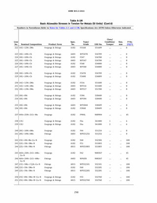
![ASME 831.3-2022
Table A-IM
Basic Allowable Stresses in Tension for Metals (SI Units) (Cont'd)
Numbers in Parentheses Refer to Notes for Tables A-1 and A-lM; Specifications Are ASTM Unless Otherwise Indicated
Basic Allowable Stress, S, MPa, at Metal
Temperature, °C
Min. [Notes (1), (2b), (3)]
Min. Min. Tensile Yield Max. Min.
Line Temp., Strength, Strength, Temp., Temp.
No. Notes °C (6) MPa MPa oc to 40 65 100 125 150 175 200
222 (9) (21) (26) -198 517 207 816 138 138 138 138 138 138 134
223 (32) (37) -198 517 207 816 138 138 138 138 138 138 138
224 (9) (21) (28) -254 517 207 816 138 138 138 138 138 138 138
225 (28) (32) (37) -254 517 207 816 138 138 138 138 138 138 138
226 (9) (21) (28) -198 517 207 816 138 138 138 138 138 138 138
227 (28) (32) (37) -198 517 207 816 138 138 138 138 138 138 138
228 (9) (21) -198 517 207 816 138 138 138 138 138 138 138
229 (9) (21) -198 517 207 816 138 138 138 138 138 138 138
230 (9) (21) (26) (28) -254 517 207 816 138 138 138 138 138 138 134
231 (26) (28) (32) (37) -254 517 207 816 138 138 138 138 138 138 134
232 (26) (28) (32) -198 517 207 816 138 138 138 138 138 138 134
233 (9) (21) (26) (28) -254 517 207 816 138 138 138 138 138 134 129
234 (26) (28) (32) (37) -254 517 207 816 138 138 138 138 138 134 129
235 (26) (32) (37) -198 517 207 816 138 138 138 138 138 134 129
236 (9) (21) (26) -198 517 207 816 138 138 138 138 138 134 129
237 (26) -198 490 220 260 143 143 143 143 141 135 130
238 (35) -29 483 276 538 161 161 161 160 158 156 155
239 (35) -29 586 379 649 195 195 195 194 191 190 188
240 ... -198 650 300 454 202 202 202 202 199 192 185
241 ... -198 650 300 454 202 202 202 202 199 192 185
242 (25) -51 600 400 316 200 200 191 185 180 175 171
243 (25) -51 620 450 316 207 207 207 204 199 196 193
244 (25) -51 620 450 316 207 207 207 204 199 196 193
245 (26) -198 655 310 427 207 207 207 207 206 202 198
246 (26) -198 655 310 427 207 207 207 207 206 202 198
247 (25) -29 650 450 316 217 217 215 211 206 203 199
248 (25) -51 655 450 316 218 218 218 215 210 206 203
249 (25) -51 655 450 316 218 218 218 215 210 206 203
250 (25) -51 750 550 316 250 250 248 243 238 236 234
251 (25) -51 750 550 316 250 250 248 243 238 236 234
299](https://image.slidesharecdn.com/26162943-231229160810-282cb07a/85/ASME-B31-3-2022-Procces-piping-code-for-b31-3-326-320.jpg)
![ASME 831.3-2022
Table A-IM
Basic Allowable Stresses in Tension for Metals (SI Units) (Cont'd)
Numbers in Parentheses Refer to Notes for Tables A-1 and A-lM; Specifications Are ASTM Unless Otherwise Indicated
Basic Allowable Stress, S, MPa, at Metal Temperature, °C [Notes (1), (2b), (3)]
Line
No. 225 250 275 300 325 350 375 400 425 450 475 500 525
222 129 125 122 119 116 114 112 111 110 109 108 107 106
223 138 138 137 135 132 130 129 127 126 126 125 125 125
224 138 138 137 135 132 130 128 127 126 126 125 125 125
225 138 138 137 135 132 130 129 127 126 126 125 125 125
226 138 138 137 135 132 130 128 127 126 126 125 125 125
227 138 138 137 135 132 130 128 127 126 126 125 125 125
228 138 138 137 135 132 130 129 127 126 126 125 125 125
229 138 138 137 135 132 130 129 127 126 126 125 125 125
230 129 125 122 119 116 114 112 111 110 109 108 107 106
231 129 125 122 119 116 114 112 111 110 109 108 107 106
232 129 125 122 119 116 114 112 111 110 109 108 107 106
233 125 122 119 116 113 111 109 107 105 103 101 99.1 97.3
234 125 122 119 116 113 111 109 107 105 103 101 99.1 97.3
235 125 122 119 116 113 111 109 107 105 103 101 99.1 97.3
236 125 122 119 116 113 111 109 107 105 103 101 99.1 97.3
237 125 120 116
238 154 153 152 150 148 145 142 137 133 125 92.5 68.4 51.1
239 187 186 184 182 180 176 172 167 161 125 92.5 68.4 51.1
240 180 175 171 168 165 164 162 161 160 159 158
241 180 175 171 168 165 164 162 161 160 159 158
242 166 161 153 143 111
243 190 188 187 186 185
244 190 188 187 186 185
245 195 192 188 184 179 176 173 170 167 166
246 195 192 188 184 179 176 173 170 167 166
247 199 199 199 199 199
248 201 199 197 196 196
249 201 199 197 196 196
250 233 233 233 233 233
251 233 233 233 233 233
300](https://image.slidesharecdn.com/26162943-231229160810-282cb07a/85/ASME-B31-3-2022-Procces-piping-code-for-b31-3-327-320.jpg)
![ASME 831.3-2022
Table A-IM
Basic Allowable Stresses in Tension for Metals (SI Units) (Cont'd)
Numbers in Parentheses Refer to Notes for Tables A-1 and A-lM; Specifications Are ASTM Unless Otherwise Indicated
Basic Allowable Stress, S, MPa, at Metal Temperature, °C [Notes (1), (2b), (3)]
Line
No. 550 575 600 625 650 675 700 725 750 775 800 825
222 105 97.8 80.8 65.0 50.4 38.6 29.6 23.0 17.4 13.3 10.4 8.96
223 125 112 90.6 69.6 53.8 41.4 31.8 24.0 18.8 14.6 10.9 8.96
224 125 112 90.6 69.6 53.8 41.4 31.8 24.0 18.8 14.6 10.9 8.96
225 125 112 90.6 69.6 53.8 41.4 31.8 24.0 18.8 14.6 10.9 8.96
226 125 112 90.6 69.6 53.8 41.4 31.8 24.0 18.8 14.6 10.9 8.96
227 125 112 90.6 69.6 53.8 41.4 31.8 24.0 18.8 14.6 10.9 8.96
228 125 112 90.6 69.6 53.8 41.4 31.8 24.0 18.8 14.6 10.9 8.96
229 125 112 90.6 69.6 53.8 41.4 31.8 24.0 18.8 14.6 10.9 8.96
230 105 97.8 80.8 65.0 50.4 38.6 29.6 23.0 17.4 13.3 10.4 8.96
231 105 97.8 80.8 65.0 50.4 38.6 29.6 23.0 17.4 13.3 10.4 8.96
232 105 97.8 80.8 65.0 50.4 38.6 29.6 23.0 17.4 13.3 10.4 8.96
233 95.5 78.9 63.8 51.6 41.6 32.9 26.5 21.3 17.2 14.1 11.2 9.65
234 95.5 78.9 63.8 51.6 41.6 32.9 26.5 21.3 17.2 14.1 11.2 9.65
235 95.5 78.9 63.8 51.6 41.6 32.9 26.5 21.3 17.2 14.1 11.2 9.65
236 95.5 78.9 63.8 51.6 41.6 32.9 26.5 21.3 17.2 14.1 11.2 9.65
237
238 44.1
239 37.4 26.3 17.8 11.4 6.89
240
241
242
243
244
245
246
247
248
249
250
251
301](https://image.slidesharecdn.com/26162943-231229160810-282cb07a/85/ASME-B31-3-2022-Procces-piping-code-for-b31-3-328-320.jpg)
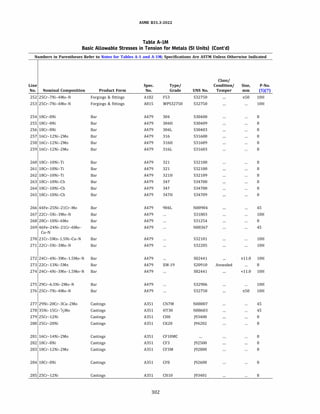
![ASME 831.3-2022
Table A-IM
Basic Allowable Stresses in Tension for Metals (SI Units) (Cont'd)
Numbers in Parentheses Refer to Notes for Tables A-1 and A-lM; Specifications Are ASTM Unless Otherwise Indicated
Basic Allowable Stress, S, MPa, at Metal
Temperature, °C
Min. [Notes (1), (2b), (3)]
Min. Min. Tensile Yield Max. Min.
Line Temp., Strength, Strength, Temp., Temp.
No. Notes °C (6) MPa MPa oc to 40 65 100 125 150 175 200
252 (25) -51 800 550 316 267 265 264 257 251 247 243
253 (25) -51 800 550 316 267 265 264 257 251 247 243
254 (26) (28) -254 517 207 816 138 138 138 138 138 134 129
255 (26) -198 517 207 816 138 138 138 138 138 134 129
256 ... -254 483 172 816 115 115 115 115 115 114 110
257 (26) (28) -254 517 207 816 138 138 138 138 138 138 134
258 (26) -198 517 207 816 138 138 138 138 138 138 134
259 ... -254 483 172 816 115 115 115 115 115 113 109
260 (28) -198 515 205 816 138 138 138 138 138 138 138
261 (28) (30) -198 515 205 816 138 138 138 138 138 138 138
262 (30) -198 515 205 816 138 138 138 138 138 138 138
263 ... -254 517 207 816 138 138 138 138 138 138 138
264 (28) (30) -254 517 207 816 138 138 138 138 138 138 138
265 ... -198 517 207 816 138 138 138 138 138 138 138
266 (26) -198 490 220 260 143 143 143 143 141 135 130
267 (25) -51 620 450 316 207 207 207 204 199 196 193
268 ... -198 655 310 454 207 207 207 207 203 196 190
269 (26) -198 655 310 427 207 207 207 207 206 202 198
270 (25) -29 650 450 316 217 217 215 211 206 203 199
271 (25) -51 655 450 316 218 218 218 215 210 206 203
272 (25) -51 680 480 316 227 227 227 227 227 227 227
273 ... -198 690 380 649 230 230 227 221 217 213 210
274 (25) -51 740 540 316 247 247 247 247 247 247 247
275 (25) -51 750 550 316 251 251 249 243 238 235 231
276 (25) -51 800 550 316 267 265 264 257 251 247 243
277 (9) (30) -198 427 172 40 115
278 (36) (39) -198 448 193 40 129
279 (9) (31) -198 448 193 816 129 129 129 129 127 125 124
280 (9) (27) (31) (35) (39) -198 448 193 816 129 129 129 129 127 125 124
281 (30) -198 483 207 40 138
282 (9) -254 483 207 427 138 138 138 138 138 134 129
283 (9) -254 483 207 454 138 138 138 138 138 138 133
284 (9) (26) (27) (31) -254 483 207 816 138 138 138 138 138 134 129
285 (27) (31) (35) -198 483 207 816 138 138 138 138 137 136 134
303](https://image.slidesharecdn.com/26162943-231229160810-282cb07a/85/ASME-B31-3-2022-Procces-piping-code-for-b31-3-330-320.jpg)
![ASME 831.3-2022
Table A-IM
Basic Allowable Stresses in Tension for Metals (SI Units) (Cont'd)
Numbers in Parentheses Refer to Notes for Tables A-1 and A-lM; Specifications Are ASTM Unless Otherwise Indicated
Basic Allowable Stress, S, MPa, at Metal Temperature, °C [Notes (1), (2b), (3)]
Line
No. 225 250 275 300 325 350 375 400 425 450 475 500 525
252 241 238 237 237 236
253 241 238 237 237 236
254 125 122 119 116 113 111 109 107 105 103 101 99.1 97.3
255 125 122 119 116 113 111 109 107 105 103 101 99.1 97.3
256 106 103 99.9 97.7 95.7 94.1 92.6 91.3 90.0 88.7 87.3 85.6 83.7
257 129 125 122 119 116 114 112 111 110 109 108 107 106
258 129 125 122 119 116 114 112 111 110 109 108 107 106
259 106 103 100 98.1 96.1 94.3 92.6 90.9 89.3 87.6 85.9 84.2 82.5
260 138 135 131 128 125 122 120 119 117 115 114 113 112
261 138 135 131 128 125 122 120 119 117 115 114 113 112
262 138 135 131 128 125 122 120 119 117 115 114 113 112
263 138 138 137 135 132 130 128 127 126 126 125 125 125
264 138 138 137 135 132 130 128 127 126 126 125 125 125
265 138 138 137 135 132 130 128 127 126 126 125 125 125
266 125 120 116
267 190 188 187 186 185
268 184 179 175 172 169 167 166 165 164 163 161
269 195 192 188 184 179 176 173 170 167 166
270 199 199 199 199 199
271 201 199 197 196 196
272 227 227 227 227 227
273 207 205 204 202 201 200 199 197 195 193 191 188 183
274 247 247 247 247 247
275 230 228 228 228 228
276 241 238 237 237 236
277
278
279 124 123 121 119 117 115 112 109 106 103 100 96.9 93.7
280 124 123 121 119 117 115 112 109 106 103 100 96.9 93.7
281
282 125 122 119 116 113 111 109 107 105 103
283 129 125 122 119 116 114 112 111 109 108 107
284 125 122 119 116 113 111 109 107 105 103 101 99.1 94.4
285 132 131 130 128 125 123 120 117 114 110 107 104 101
304](https://image.slidesharecdn.com/26162943-231229160810-282cb07a/85/ASME-B31-3-2022-Procces-piping-code-for-b31-3-331-320.jpg)
![ASME 831.3-2022
Table A-IM
Basic Allowable Stresses in Tension for Metals (SI Units) (Cont'd)
Numbers in Parentheses Refer to Notes for Tables A-1 and A-lM; Specifications Are ASTM Unless Otherwise Indicated
Basic Allowable Stress, S, MPa, at Metal Temperature, °C [Notes (1), (2b), (3)]
Line
No. 550 575 600 625 650 675 700 725 750 775 800 825
252
253
254 95.5 78.9 63.8 51.6 41.6 32.9 26.5 21.3 17.2 14.1 11.2 9.65
255 95.5 78.9 63.8 51.6 41.6 32.9 26.5 21.3 17.2 14.1 11.2 9.65
256 81.4 40.4 33.2 26.7 21.9 18.2 15.0 12.4 8.87 7.20 6.58 6.21
257 105 97.8 80.8 65.0 50.4 38.6 29.6 23.0 17.4 13.3 10.4 8.96
258 105 97.8 80.8 65.0 50.4 38.6 29.6 23.0 17.4 13.3 10.4 8.96
259 80.8 73.0 67.9 58.0 43.6 33.0 25.3 18.8 14.0 10.4 7.99 6.89
260 88.7 59.2 44.0 32.9 24.5 18.3 12.5 8.49 6.19 4.28 2.75 1.74
261 100 76.5 58.7 46.0 36.8 28.7 23.0 18.4 14.5 11.5 9.02 6.83
262 100 76.5 58.7 46.0 36.8 28.7 23.0 18.4 14.5 11.5 9.02 6.83
263 97.6 75.9 57.2 40.2 30.3 23.2 16.2 11.4 8.97 7.08 5.89 5.52
264 125 112 90.6 69.6 53.8 41.4 31.8 24.0 18.8 14.6 10.9 8.96
265 125 112 90.6 69.6 53.8 41.4 31.8 24.0 18.8 14.6 10.9 8.96
266
267
268
269
270
271
272
273 179 174 132 83.6 56.1
274
275
276
277
278
279 68.1 53.5 42.1 33.2 25.9 20.3 16.5 13.2 10.1 7.35 5.89 5.52
280 73.2 64.4 56.5 49.0 41.0 33.5 25.4 18.3 12.8 9.01 6.59 5.52
281
282
283
284 75.3 60.4 49.0 40.1 32.8 27.2 23.4 19.6 16.8 14.7 12.8 11.7
285 68.2 53.7 42.1 33.2 25.9 20.3 16.4 13.3 10.2 7.25 5.74 5.33
305](https://image.slidesharecdn.com/26162943-231229160810-282cb07a/85/ASME-B31-3-2022-Procces-piping-code-for-b31-3-332-320.jpg)
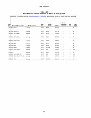
![ASME 831.3-2022
Table A-IM
Basic Allowable Stresses in Tension for Metals (SI Units) (Cont'd)
Numbers in Parentheses Refer to Notes for Tables A-1 and A-lM; Specifications Are ASTM Unless Otherwise Indicated
Basic Allowable Stress, S, MPa, at Metal
Temperature, °C
Min. [Notes (1), (2b), (3)]
Min. Min. Tensile Yield Max. Min.
Line Temp., Strength, Strength, Temp., Temp.
No. Notes °C (6) MPa MPa oc to 40 65 100 125 150 175 200
286 (9) (27) (31) (35) (39) -198 483 207 816 138 138 138 138 137 136 134
287 (9) (28) -198 485 205 816 138 138 138 138 138 138 135
288 (9) (26) (27) (30) -254 483 207 816 138 138 138 138 138 134 129
(35) (36) (39) -198 427 241 40 142
290 (35) (39) -198 448 241 40 149
291 (9) (56) -254 531 241 371 161 161 161 160 156 153 151
292 (9) (26) (56) -254 531 241 371 161 161 161 160 156 153 151
293 (35) (39) -198 552 276 482 184 184 184 184 184 184 184
294 (9) (25) -51 620 415 260 207 207 207 202 198 197 196
295 (35) -29 621 448 649 207 207 207 205 203 201 199
296 (9) -51 655 448 316 218 218 216 208 201 197 195
297 (9) (25) -51 689 448 316 230 230 227 221 216 212 209
298 (9) (35) -29 758 552 371 253 253 253 251 248 245 244
307](https://image.slidesharecdn.com/26162943-231229160810-282cb07a/85/ASME-B31-3-2022-Procces-piping-code-for-b31-3-334-320.jpg)
![ASME 831.3-2022
Table A-IM
Basic Allowable Stresses in Tension for Metals (SI Units) (Cont'd)
Numbers in Parentheses Refer to Notes for Tables A-1 and A-lM; Specifications Are ASTM Unless Otherwise Indicated
Basic Allowable Stress, S, MPa, at Metal Temperature, °C [Notes (1), (2b), (3)]
Line
No. 225 250 275 300 325 350 375 400 425 450 475 500 525
286 132 131 130 128 125 123 120 117 114 110 107 104 101
287 132 130 128 127 127 126 126 126 125 125 124 124 124
288 125 122 119 116 113 111 109 107 105 103 101 99.1 97.3
289
290
291 146 142 138 135 132 130 127
292 146 142 138 135 132 130 127
293 184 184 184 184 184 184 184 184 184 184 184 184
294 196 196 192
295 198 197 195 193 190 187 182 120 105 82.1 59.9 41.8
296 194 194 194 194 194
297 207 206 205 204 204
298 242 240 238 236 232 228 224
308](https://image.slidesharecdn.com/26162943-231229160810-282cb07a/85/ASME-B31-3-2022-Procces-piping-code-for-b31-3-335-320.jpg)
![ASME 831.3-2022
Table A-IM
Basic Allowable Stresses in Tension for Metals (SI Units) (Cont'd)
Numbers in Parentheses Refer to Notes for Tables A-1 and A-lM; Specifications Are ASTM Unless Otherwise Indicated
Basic Allowable Stress, S, MPa, at Metal Temperature, °C [Notes (1), (2b), (3)]
Line
No. 550 575 600 625 650 675 700 725 750 775 800 825
286 68.2 53.7 42.1 33.2 25.9 20.3 16.4 13.3 10.2 7.25 5.74 5.33
287 98.3 77.2 57.7 39.9 30.0 23.2 16.3 11.2 8.93 7.08 5.77 5.32
288 95.5 75.9 57.2 40.2 30.3 23.2 16.2 11.4 8.97 7.08 5.89 5.52
289
290
291
292
293
294
295 28.7 20.1 14.3 9.77 6.89
296
297
298
309](https://image.slidesharecdn.com/26162943-231229160810-282cb07a/85/ASME-B31-3-2022-Procces-piping-code-for-b31-3-336-320.jpg)
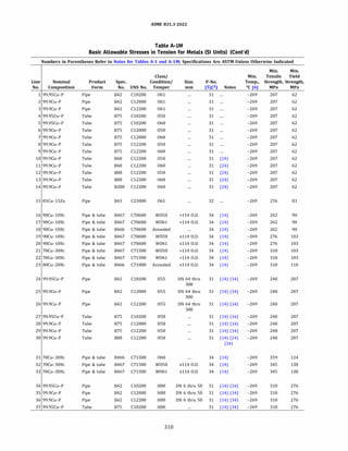
![ASME 831.3-2022
Table A-IM
Basic Allowable Stresses in Tension for Metals (SI Units) (Cont'd)
Numbers in Parentheses Refer to Notes for Tables A-1 and A-lM; Specifications Are ASTM Unless Otherwise Indicated
Basic Allowable Stress, S, MPa, at Metal Temperature, °C [Notes (1), (2b)]
Max. Min.
Line Temp., Temp.
No. oc to 40 65 100 125 150 175 200 225 250 275 300 325 350 375
1 260 41.4 34.9 33.5 32.9 32.2 28.0 21.7 16.7 12.9 11.6
2 260 41.4 34.9 33.5 32.9 32.2 28.0 21.7 16.7 12.9 11.6
3 260 41.4 34.9 33.5 32.9 32.2 28.0 21.7 16.7 12.9 11.6
4 260 41.4 34.9 33.5 32.9 32.2 28.0 21.7 16.7 12.9 11.6
5 260 41.4 34.9 33.5 32.9 32.2 28.0 21.7 16.7 12.9 11.6
6 260 41.4 34.9 33.5 32.9 32.2 28.0 21.7 16.7 12.9 11.6
7 260 41.4 34.9 33.5 32.9 32.2 28.0 21.7 16.7 12.9 11.6
8 260 41.4 34.9 33.5 32.9 32.2 28.0 21.7 16.7 12.9 11.6
9 260 41.4 34.9 33.5 32.9 32.2 28.0 21.7 16.7 12.9 11.6
10 260 41.4 34.9 33.5 32.9 32.2 28.0 21.7 16.7 12.9 11.6
11 260 41.4 34.9 33.5 32.9 32.2 28.0 21.7 16.7 12.9 11.6
12 260 41.4 34.9 33.5 32.9 32.2 28.0 21.7 16.7 12.9 11.6
13 260 41.4 34.9 33.5 32.9 32.2 28.0 21.7 16.7 12.9 11.6
14 260 41.4 34.9 33.5 32.9 32.2 28.0 21.7 16.7 12.9 11.6
15 232 55.2 54.7 54.7 54.7 54.7 54.7 36.4 17.5 13.8
16 316 59.8 58.0 56.1 54.9 53.8 52.9 52.0 51.2 50.4 49.7 45.1 39.3
17 316 59.8 58.0 56.1 54.9 53.8 52.9 52.0 51.2 50.4 49.7 45.1 39.3
18 316 59.8 58.0 56.1 54.9 53.8 52.9 52.0 51.2 50.4 49.7 45.1 39.3
19 316 68.9 67.0 65.1 63.7 62.4 61.1 60.0 59.1 58.3 51.3 45.1 39.3
20 316 68.9 67.0 65.1 63.7 62.4 61.1 60.0 59.1 58.3 51.3 45.1 39.3
21 371 68.9 66.6 64.6 63.2 61.9 60.7 59.5 58.4 57.4 56.2 55.5 54.9 54.3 53.8
22 371 68.9 66.6 64.6 63.2 61.9 60.7 59.5 58.4 57.4 56.2 55.5 54.9 54.3 53.8
23 371 73.5 72.8 72.1 71.4 70.6 69.6 68.3 66.6 64.7 62.4 60.0 56.2 51.9 48.3
24 204 82.7 80.0 74.1 71.3 69.2 67.4 65.7 65.3
25 204 82.7 80.0 74.1 71.3 69.2 67.4 65.7 65.3
26 204 82.7 80.0 74.1 71.3 69.2 67.4 65.7 65.3
27 204 82.7 80.0 74.1 71.3 69.2 67.4 65.7 65.3
28 204 82.7 80.0 74.1 71.3 69.2 67.4 65.7 65.3
29 204 82.7 80.0 74.1 71.3 69.2 67.4 65.7 65.3
30 204 82.7 80.0 74.1 71.3 69.2 67.4 65.7 65.3
31 371 82.7 79.8 77.5 75.9 74.3 72.9 71.5 70.2 68.9 67.8 66.8 65.9 65.3 64.8
32 371 91.9 88.7 86.1 84.3 82.6 81.0 79.4 78.0 76.6 75.3 74.2 73.2 72.5 71.7
33 371 91.9 88.7 86.1 84.3 82.6 81.0 79.4 78.0 76.6 75.3 74.2 73.2 72.5 71.7
34 204 103 100 92.6 89.1 86.5 84.3 35.8 29.6
35 204 103 100 92.6 89.1 86.5 84.3 35.8 29.6
36 204 103 100 92.6 89.1 86.5 84.3 35.8 29.6
37 204 103 100 92.6 89.1 86.5 84.3 35.8 29.6
311](https://image.slidesharecdn.com/26162943-231229160810-282cb07a/85/ASME-B31-3-2022-Procces-piping-code-for-b31-3-338-320.jpg)
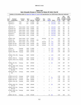
![ASME 831.3-2022
Table A-IM
Basic Allowable Stresses in Tension for Metals (SI Units) (Cont'd)
Numbers in Parentheses Refer to Notes for Tables A-1 and A-lM; Specifications Are ASTM Unless Otherwise Indicated
Basic Allowable Stress, S, MPa, at Metal Temperature, °C [Notes (1), (2b)]
Max. Min.
Line Temp., Temp.
No. oc to 40 65 100 125 150 175 200 225 250 275 300 325 350 375
38 204 103 100 92.6 89.1 86.5 84.3 35.8 29.6
39 204 103 100 92.6 89.1 86.5 84.3 35.8 29.6
40 260 46.0 39.1 37.1 36.5 34.2 28.0 21.7 16.7 12.9 11.6
41 260 46.0 39.1 37.1 36.5 34.2 28.0 21.7 16.7 12.9 11.6
42 260 46.0 39.1 37.1 36.5 34.2 28.0 21.7 16.7 12.9 11.6
43 260 46.0 39.1 37.1 36.5 34.2 28.0 21.7 16.7 12.9 11.6
44 260 46.0 39.1 37.1 36.5 34.2 28.0 21.7 16.7 12.9 11.6
45 260 46.0 39.1 37.1 36.5 34.2 28.0 21.7 16.7 12.9 11.6
46 316 68.9 67.0 65.1 63.7 62.4 61.1 60.0 59.1 58.3 51.3 45.1 39.3
47 204 82.7 82.7 82.7 82.7 82.7 75.4 50.8 31.9
48 371 91.9 88.7 86.1 84.3 82.6 81.0 79.4 78.0 76.6 75.3 74.2 73.2 72.5 71.7
49 260 138 137 136 135 135 134 133 131 130 130
50 260 138 137 136 135 135 134 133 131 130 130
51 260 50.6 42.8 40.8 40.2 34.2 28.0 21.7 16.7 12.9 11.6
52 204 82.7 82.7 82.7 82.7 82.7 75.4 50.8 31.9
53 204 106 99.8 94.5 91.1 71.4 52.8 17.0 13.8
54 204 110 110 110 110 110 110 110 110
55 204 120 120 120 120 118 118 20.0 17.2
56 204 156 156 156 156 156 156 156 156
57 232 64.4 64.4 62.6 59.1 55.7 53.0 51.2 50.3 50.1
58 40 68.9
59 149 78.1 69.6 64.9 62.5 60.3
60 204 73.5 73.5 73.5 73.5 73.5 73.5 73.5 73.5
61 204 73.5 66.4 65.3 64.6 63.3 61.5 59.6 58.1
62 288 73.5 66.4 65.3 64.6 63.3 61.5 59.6 58.1 57.5 57.5 57.3
63 204 82.7 82.7 82.7 82.7 82.7 82.7 82.7 82.7
64 204 82.7 82.7 82.7 82.7 82.7 82.7 82.7 82.7
65 177 91.9 91.9 91.9 91.9 91.9 91.9 91.9
66 177 101 101 101 101 101 101 101
67 177 115 115 115 115 115 115 115
68 316 115 108 104 102 99.8 98.6 97.8 97.5 97.4 97.4 65.9 43.7
313](https://image.slidesharecdn.com/26162943-231229160810-282cb07a/85/ASME-B31-3-2022-Procces-piping-code-for-b31-3-340-320.jpg)
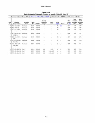
![ASME 831.3-2022
Table A-IM
Basic Allowable Stresses in Tension for Metals (SI Units) (Cont'd)
Numbers in Parentheses Refer to Notes for Tables A-1 and A-lM; Specifications Are ASTM Unless Otherwise Indicated
Basic Allowable Stress, S, MPa, at Metal Temperature, °C [Notes (1), (2b)]
Max. Min.
Line Temp., Temp.
No. oc to 40 65 100 125 150 175 200 225 250 275 300 325 350 375
69 316 115 115 115 115 115 115 115 115 115 115 115 115
70 40 129
71 260 138 131 128 128 128 128 128 128 101 95.8
72 177 147 147 147 147 147 147 147
73 260 184 184 184 184 184 184 184 184 184 184
74 177 207 207 207 207 207 207 207
75 177 253 253 253 253 253 253 253
76 149 195 179 176 176 176
77 149 161 139 137 137 137
78 149 138 119 117 117 117
315](https://image.slidesharecdn.com/26162943-231229160810-282cb07a/85/ASME-B31-3-2022-Procces-piping-code-for-b31-3-342-320.jpg)
![ASME 831.3-2022
Table A-IM
Basic Allowable Stresses in Tension for Metals (SI Units) (Cont'd)
Numbers in Parentheses Refer to Notes for Tables A-1 and A-lM; Specifications Are ASTM Unless Otherwise Indicated
Basic Allowable Stress, S, MPa, at Metal Temperature, °C
[Notes (1), (2b)]
Min. Min. Min.
Min. Tensile Yield Max. Temp.
Line Temp., Strength, Strength, Temp., to
No. Notes °C (6) MPa MPa oc 40 65 100 125 150 175 200 225 250
1 ... -198 345 69 649 46.0 44.7 43.9 43.6 43.3 43.2 43.2 43.2 43.2
2 ... -198 345 69 649 46.0 44.7 43.9 43.6 43.3 43.2 43.2 43.2 43.2
3 ... -198 379 83 316 55.2 55.2 55.2 55.2 55.2 55.2 55.2 55.2 55.2
4 ... -198 379 83 316 55.2 55.2 55.2 55.2 55.2 55.2 55.2 55.2 55.2
5 ... -198 345 83 649 55.2 53.8 52.8 52.3 51.9 51.7 51.6 51.6 51.6
6 ... -198 345 83 649 55.2 53.8 52.8 52.3 51.9 51.7 51.6 51.6 51.6
7 ... -198 379 103 316 68.9 68.9 68.9 68.9 68.9 68.9 68.9 68.9 68.9
8 ... -198 379 103 316 68.9 68.9 68.9 68.9 68.9 68.9 68.9 68.9 68.9
9 ... -198 483 172 482 115 106 99.7 96.2 93.6 91.9 90.9 90.4 90.4
10 ... -198 483 172 482 115 106 99.7 96.2 93.6 91.9 90.9 90.4 90.4
11 ... -198 448 172 816 115 115 115 115 115 115 115 115 115
12 ... -198 517 172 649 115 115 115 115 115 115 115 115 115
13 (62) -198 448 172 899 115 115 115 115 115 115 115 115 115
14 (62) -198 448 172 899 115 115 115 115 115 115 115 115 115
15 (62) -198 448 172 899 115 115 115 115 115 115 115 115 115
16 ... -198 483 193 482 129 119 112 108 105 103 102 101 101
17 ... -198 483 193 482 129 119 112 108 105 103 102 101 101
18 ... -198 517 193 427 129 129 129 129 129 129 129 129 129
19 ... -198 517 193 427 129 129 129 129 129 129 129 129 129
20 ... -198 414 207 316 138 138 138 137 137 137 137 137 136
21 ... -198 414 207 316 138 138 138 137 137 137 137 137 136
22 ... -198 517 207 816 138 138 138 138 138 138 138 138 138
23 ... -198 552 207 649 138 138 138 138 138 138 138 138 138
24 ... -198 552 207 649 138 138 138 138 138 138 138 138 138
25 (61) -198 517 207 816 138 138 138 138 138 138 138 138 138
26 ... -198 505 215 454 143 143 143 143 143 143 143 143 143
27 ... -198 448 276 316 149 149 149 149 149 149 149 149 148
28 ... -198 448 276 316 149 149 149 149 149 149 149 149 148
29 ... -198 552 241 427 161 161 161 161 161 161 161 161 161
30 ... -198 552 241 427 161 161 161 161 161 161 161 161 161
31 ... -198 552 241 427 161 161 161 161 161 161 161 161 161
32 ... -198 585 240 538 161 161 161 161 161 161 161 161 161
33 ... -198 585 240 538 161 161 161 161 161 161 161 161 161
34 ... -198 585 240 538 161 161 161 161 161 161 161 161 161
317](https://image.slidesharecdn.com/26162943-231229160810-282cb07a/85/ASME-B31-3-2022-Procces-piping-code-for-b31-3-344-320.jpg)
![ASME 831.3-2022
Table A-IM
Basic Allowable Stresses in Tension for Metals (SI Units) (Cont'd)
Numbers in Parentheses Refer to Notes for Tables A-1 and A-lM; Specifications Are ASTM Unless Otherwise Indicated
Basic Allowable Stress, S, MPa, at Metal Temperature, °C [Notes (1), (2b)]
Line
No. 275 300 325 350 375 400 425 450 475 500 525 550 575
1 43.2 43.2 43.1 42.9 42.6 42.1 41.5 40.7 33.1 27.4 22.8 18.7 15.6
2 43.2 43.2 43.1 42.9 42.6 42.1 41.5 40.7 33.1 27.4 22.8 18.7 15.6
3 55.2 55.2 55.2
4 55.2 55.2 55.2
5 51.6 51.6 51.6 51.5 51.2 50.7 49.9 41.4 33.1 27.4 22.8 18.7 15.6
6 51.6 51.6 51.6 51.5 51.2 50.7 49.9 41.4 33.1 27.4 22.8 18.7 15.6
7 68.9 68.9 68.9
8 68.9 68.9 68.9
9 90.4 90.4 90.4 90.4 89.8 89.0 88.0 79.7 59.9 55.2
10 90.4 90.4 90.4 90.4 89.8 89.0 88.0 79.7 59.9 55.2
11 115 115 115 115 115 115 115 115 115 115 115 113 107
12 115 115 115 115 115 115 115 115 115 84.8 58.4 39.7 27.0
13 115 115 113 110 108 106 104 102 100 98.6 97.1 95.7 91.8
14 115 115 113 110 108 106 104 102 100 98.6 97.1 95.7 91.8
15 115 115 113 110 108 106 104 102 100 98.6 97.1 95.7 92.5
16 101 101 101 101 100 99.6 98.6 79.7 59.9 55.2
17 101 101 101 101 100 99.6 98.6 79.7 59.9 55.2
18 129 129 127 125 122 121 119 119
19 129 129 127 125 122 121 119 119
20 135 133 130
21 135 133 130
22 138 138 138 138 138 138 138 138 138 138 138 136 107
23 138 138 138 138 138 138 138 138 138 84.8 58.4 39.7 27.0
24 138 138 138 138 138 138 138 138 138 84.8 58.4 39.7 27.0
25 138 138 138 138 138 138 138 138 138 138 138 136 107
26 140 137 133 130 125 122 119 116 113
27 146 144 141
28 146 144 141
29 161 161 161 161 161 160 157 156
30 161 161 161 161 161 160 157 156
31 161 161 161 161 161 160 157 156
32 161 161 161 161 161 160 159 158 157 156 155 153
33 161 161 161 161 161 160 159 158 157 156 155 153
34 161 161 161 161 161 160 159 158 157 156 155 153
318](https://image.slidesharecdn.com/26162943-231229160810-282cb07a/85/ASME-B31-3-2022-Procces-piping-code-for-b31-3-345-320.jpg)
![ASME 831.3-2022
Table A-IM
Basic Allowable Stresses in Tension for Metals (SI Units) (Cont'd)
Numbers in Parentheses Refer to Notes for Tables A-1 and A-lM; Specifications Are ASTM Unless Otherwise Indicated
Basic Allowable Stress, S, MPa, at Metal Temperature, °C [Notes (1), (2b)]
Line
No. 600 625 650 675 700 725 750 775 800 825 850 875 900
1 12.9 10.0 8.27
2 12.9 10.0 8.27
3
4
5 12.9 10.0 8.27
6 12.9 10.0 8.27
7
8
9
10
11 83.8 63.9 44.7 29.8 15.5 11.7 8.68 7.20 6.25 5.11
12 19.2 15.0 13.8
13 75.7 62.6 50.6 41.2 33.6 27.7 22.6 18.3 15.0 11.9 9.03 7.35 5.86
14 75.7 62.6 50.6 41.2 33.6 27.7 22.6 18.3 15.0 11.9 9.03 7.35 5.86
15 84.5 69.5 56.7 46.8 38.5 31.5 25.5 20.7 17.0 13.9 11.2 9.33 7.58
16
17
18
19
20
21
22 83.8 63.9 44.7 29.8 15.5 11.7 8.68 7.20 6.25 5.11
23 19.2 15.0 13.8
24 19.2 15.0 13.8
25 83.8 63.9 44.7 29.8 15.5 11.7 8.68 7.20 6.25 5.11
26
27
28
29
30
31
32
33
34
319](https://image.slidesharecdn.com/26162943-231229160810-282cb07a/85/ASME-B31-3-2022-Procces-piping-code-for-b31-3-346-320.jpg)
![ASME 831.3-2022
Table A-IM
Basic Allowable Stresses in Tension for Metals (SI Units) (Cont'd)
Numbers in Parentheses Refer to Notes for Tables A-1 and A-lM; Specifications Are ASTM Unless Otherwise Indicated
Basic Allowable Stress, S, MPa, at Metal Temperature, °C
[Notes (1), (2b)]
Min. Min. Min.
Min. Tensile Yield Max. Temp.
Line Temp., Strength, Strength, Temp., to
No. Notes °C (6) MPa MPa oc 40 65 100 125 150 175 200 225 250
35 ... -198 585 240 538 161 161 161 161 161 161 161 161 161
36 ... -198 585 240 538 161 161 161 161 161 161 161 161 161
37 ... -198 621 241 538 161 161 161 161 161 161 161 161 161
38 ... -198 621 241 427 161 161 161 161 161 161 161 161 161
39 ... -198 586 241 427 161 161 161 161 161 161 161 157 154
40 ... -198 586 241 427 161 161 161 161 161 161 161 157 154
41 ... -198 586 241 427 161 161 161 161 161 161 161 157 154
42 ... -198 552 241 649 161 161 161 161 161 161 161 161 161
43 ... -198 552 241 649 161 161 161 161 161 161 161 161 161
44 ... -198 586 241 482 160 160 160 160 160 160 160 160 160
45 ... -198 586 240 482 160 160 160 160 160 160 160 160 160
46 ... -198 621 276 899 184 184 184 184 184 184 184 180 175
47 ... -198 621 276 899 184 184 184 184 184 184 184 180 175
48 ... -198 621 276 899 184 184 184 184 184 184 184 180 175
49 ... -198 621 276 899 184 184 184 184 184 184 184 180 175
so ... -198 689 276 427 184 184 184 184 184 184 184 184 184
51 ... -198 689 276 816 184 184 184 184 184 184 184 184 178
52 ... -198 689 276 816 184 184 184 184 184 184 184 184 178
53 ... -198 648 276 427 184 184 184 184 184 177 171 166 162
54 ... -198 648 276 427 184 184 184 184 184 177 171 166 162
55 ... -198 689 276 427 184 184 184 184 184 184 184 184 184
56 ... -198 689 283 677 188 188 188 188 188 188 188 188 187
57 ... -198 689 283 677 188 188 188 188 188 188 188 188 187
58 ... -198 689 283 677 188 188 188 188 188 188 188 188 187
59 (54) -198 586 379 260 195 195 195 195 195 195 195 195 195
60 (54) -198 586 379 260 195 195 195 195 195 195 195 195 195
61 ... -198 655 310 427 207 207 207 207 206 202 198 195 192
62 ... -198 655 310 427 207 207 207 207 206 202 198 195 192
63 ... -198 655 310 427 207 207 207 207 206 202 198 195 192
64 ... -198 689 310 427 207 207 207 207 206 202 198 195 192
65 ... -198 689 310 427 207 207 207 207 206 202 198 195 192
66 ... -198 689 310 427 207 207 207 207 206 202 198 195 192
321](https://image.slidesharecdn.com/26162943-231229160810-282cb07a/85/ASME-B31-3-2022-Procces-piping-code-for-b31-3-348-320.jpg)
![ASME 831.3-2022
Table A-IM
Basic Allowable Stresses in Tension for Metals (SI Units) (Cont'd)
Numbers in Parentheses Refer to Notes for Tables A-1 and A-lM; Specifications Are ASTM Unless Otherwise Indicated
Basic Allowable Stress, S, MPa, at Metal Temperature, °C [Notes (1), (2b)]
Line
No. 275 300 325 350 375 400 425 450 475 500 525 550 575
35 161 161 161 161 161 160 159 158 157 156 155 153
36 161 161 161 161 161 160 159 158 157 156 155 153
37 160 158 156 154 153 152 151 150 149 136 132 130
38 160 158 156 154 153 152 151 150
39 151 148 146 143 141 138 136 136
40 151 148 146 143 141 138 136 136
41 151 148 146 143 141 138 136 136
42 161 161 161 161 161 161 161 161 161 84.8 58.4 39.7 27.0
43 161 161 161 161 161 161 161 161 161 84.8 58.4 39.7 27.0
44 160 160 160 160 160 160 160 160 160 160
45 160 160 160 160 160 160 160 160 160 160
46 170 166 163 160 158 156 154 153 153 152 151 151 151
47 170 166 163 160 158 156 154 153 153 152 151 151 151
48 170 166 163 160 158 156 154 153 153 152 151 151 151
49 170 166 163 160 158 156 154 153 153 152 151 151 151
so 184 184 184 184 183 180 178 178
51 173 169 165 162 160 158 157 155 154 135 134 133 129
52 173 169 165 162 160 158 157 155 154 135 134 133 129
53 158 155 152 149 74.2 61.1 50.3 49.6
54 158 155 152 149 74.2 61.1 50.3 49.6
55 184 184 184 184 182 180 178 178
56 183 177 172 169 165 162 159 157 156 155 154 143 118
57 183 177 172 169 165 162 159 157 156 155 154 143 118
58 183 177 172 169 165 162 159 157 156 155 154 143 118
59 195
60 195
61 188 183 179 176 173 170 168 167
62 188 183 179 176 173 170 168 167
63 188 183 179 176 173 170 168 167
64 188 183 179 176 173 170 168 167
65 188 183 179 176 173 170 168 167
66 188 183 179 176 173 170 168 167
322](https://image.slidesharecdn.com/26162943-231229160810-282cb07a/85/ASME-B31-3-2022-Procces-piping-code-for-b31-3-349-320.jpg)
![ASME 831.3-2022
Table A-IM
Basic Allowable Stresses in Tension for Metals (SI Units) (Cont'd)
Numbers in Parentheses Refer to Notes for Tables A-1 and A-lM; Specifications Are ASTM Unless Otherwise Indicated
Basic Allowable Stress, S, MPa, at Metal Temperature, °C [Notes (1), (2b)]
Line
No. 600 625 650 675 700 725 750 775 800 825 850 875 900
35
36
37
38
39
40
41
42 19.2 15.0 13.8
43 19.2 15.0 13.8
44
45
46 117 96.2 79.3 65.6 54.4 45.0 37.2 30.6 25.1 20.5 16.5 13.0 9.8
47 117 96.2 79.3 65.6 54.4 45.0 37.2 30.6 25.1 20.5 16.5 13.0 9.8
48 117 96.2 79.3 65.6 54.4 45.0 37.2 30.6 25.1 20.5 16.5 13.0 9.8
49 117 96.2 79.3 65.6 54.4 45.0 37.2 30.6 25.1 20.5 16.5 13.0 9.8
50
51 115 94.2 77.3 64.9 54.7 44.7 36.1 29.2 23.6 20.7
52 115 94.2 77.3 64.9 54.7 44.7 36.1 29.2 23.6 20.7
53
54
55
56 99.1 81.6 67.0 54.6 42.2
57 99.1 81.6 67.0 54.6 42.2
58 99.1 81.6 67.0 54.6 42.2
59
60
61
62
63
64
65
66
323](https://image.slidesharecdn.com/26162943-231229160810-282cb07a/85/ASME-B31-3-2022-Procces-piping-code-for-b31-3-350-320.jpg)
![ASME 831.3-2022
Table A-IM
Basic Allowable Stresses in Tension for Metals (SI Units) (Cont'd)
Numbers in Parentheses Refer to Notes for Tables A-1 and A-lM; Specifications Are ASTM Unless Otherwise Indicated
Basic Allowable Stress, S, MPa, at Metal Temperature, °C
[Notes (1), (2b)]
Min. Min. Min.
Min. Tensile Yield Max. Temp.
Line Temp., Strength, Strength, Temp., to
No. Notes °C (6) MPa MPa oc 40 65 100 125 150 175 200 225 250
67 ... -198 689 310 427 207 207 207 207 207 207 207 204 202
68 ... -198 689 310 427 207 207 207 207 207 207 207 204 202
69 ... -198 586 241 427 161 161 161 161 161 161 154 149 144
70 ... -198 586 241 427 161 161 161 161 161 161 154 149 144
71 ... -198 586 241 427 161 161 161 161 161 161 154 149 144
72 ... -198 689 310 427 207 207 207 207 207 207 207 207 206
73 ... -198 689 310 427 207 207 207 207 207 207 207 207 206
74 ... -198 689 310 427 207 207 207 207 207 207 207 207 206
75 ... -198 689 310 427 207 207 207 207 207 207 207 207 200
76 ... -198 689 310 427 207 207 207 207 207 207 207 207 200
77 ... -198 689 310 427 207 207 207 207 207 207 207 207 200
78 ... -198 725 310 427 207 207 207 207 207 207 204 202 199
79 ... -198 725 310 427 207 207 207 207 207 207 204 202 199
80 ... -198 725 310 427 207 207 207 207 207 207 204 202 199
81 ... -198 689 310 427 207 207 207 207 207 207 207 207 207
82 ... -198 689 310 427 207 207 207 207 207 207 207 207 207
83 ... -198 758 352 427 234 234 234 234 234 234 234 234 234
84 ... -198 758 352 427 234 234 234 234 234 234 234 234 234
85 ... -198 758 352 427 234 234 234 234 234 234 234 234 234
86 ... -198 758 352 427 234 234 234 234 234 234 234 234 234
87 ... -198 758 352 427 234 234 234 234 234 234 234 234 234
88 (19) (60) -198 827 414 649 276 276 276 274 273 272 270 269 267
89 (19) (60) -198 827 414 649 276 276 276 274 273 272 270 269 267
90 ... -198 758 310 899 207 207 207 207 207 207 207 207 207
91 ... -198 758 310 899 207 207 207 207 207 207 207 207 207
92 ... -198 758 310 899 207 207 207 207 207 207 207 207 207
93 ... -198 750 380 427 250 231 209 200 193 187 181 176 172
94 ... -198 750 380 427 250 231 209 200 193 187 181 176 172
95 ... -198 750 380 427 250 231 209 200 193 187 181 176 172
96 ... -198 345 83 649 55.2 53.8 52.8 52.3 51.9 51.7 51.6 51.6 51.6
97 ... -198 345 83 649 55.2 53.8 52.8 52.3 51.9 51.7 51.6 51.6 51.6
98 ... -198 379 103 316 68.9 68.9 68.9 68.9 68.9 68.9 68.9 68.9 68.9
99 ... -198 379 138 316 91.9 91.9 91.9 91.9 91.9 91.9 91.9 91.9 91.9
100 ... -198 448 172 899 115 115 115 115 115 115 115 115 115
101 ... -198 448 172 899 115 115 115 115 115 115 115 115 115
325](https://image.slidesharecdn.com/26162943-231229160810-282cb07a/85/ASME-B31-3-2022-Procces-piping-code-for-b31-3-352-320.jpg)
![ASME 831.3-2022
Table A-IM
Basic Allowable Stresses in Tension for Metals (SI Units) (Cont'd)
Numbers in Parentheses Refer to Notes for Tables A-1 and A-lM; Specifications Are ASTM Unless Otherwise Indicated
Basic Allowable Stress, S, MPa, at Metal Temperature, °C [Notes (1), (2b)]
Line
No. 275 300 325 350 375 400 425 450 475 500 525 550 575
67 197 193 189 185 182 180 177 177
68 197 193 189 185 182 180 177 177
69 140 137 135 133 132 131 129 128
70 140 137 135 133 132 131 129 128
71 140 137 135 133 132 131 129 128
72 202 197 192 188 184 180 176 176
73 202 197 192 188 184 180 176 176
74 202 197 192 188 184 180 176 176
75 194 188 184 180 177 175 174 173
76 194 188 184 180 177 175 174 173
77 194 188 184 180 177 175 174 173
78 197 193 190 188 186 184 182 180
79 197 193 190 188 186 184 182 180
80 197 193 190 188 186 184 182 180
81 207 207 207 207 207 207 206 206
82 207 207 207 207 207 207 206 206
83 234 234 234 234 234 234 234 234
84 234 234 234 234 234 234 234 234
85 234 234 234 234 234 233 231 230
86 234 234 234 234 234 233 231 230
87 234 234 234 234 234 233 231 230
88 265 262 260 257 255 252 251 249 247 245 242 215 194
89 265 262 260 257 255 252 251 249 247 245 242 215 194
90 207 207 203 199 197 196 195 195 195 195 195 195 183
91 207 207 203 199 197 196 195 195 195 195 195 195 183
92 207 207 203 199 197 196 195 195 195 195 195 195 183
93 169 165 163 161 159 157 156 155
94 169 165 163 161 159 157 156 155
95 169 165 163 161 159 157 156 155
96 51.6 51.6 51.6 51.5 51.2 50.7 49.9 41.4 33.1 27.4 22.8 18.7 15.6
97 51.6 51.6 51.6 51.5 51.2 50.7 49.9 41.4 33.1 27.4 22.8 18.7 15.6
98 68.9 68.9 68.9
99 91.9 91.9 91.9
100 115 115 113 110 108 105 104 102 100 98.6 97.1 95.9 91.8
101 115 115 113 110 108 105 104 102 100 98.6 97.1 96.1 94.1
326](https://image.slidesharecdn.com/26162943-231229160810-282cb07a/85/ASME-B31-3-2022-Procces-piping-code-for-b31-3-353-320.jpg)
![ASME 831.3-2022
Table A-IM
Basic Allowable Stresses in Tension for Metals (SI Units) (Cont'd)
Numbers in Parentheses Refer to Notes for Tables A-1 and A-lM; Specifications Are ASTM Unless Otherwise Indicated
Basic Allowable Stress, S, MPa, at Metal Temperature, °C [Notes (1), (2b)]
Line
No. 600 625 650 675 700 725 750 775 800 825 850 875 900
67
68
69
70
71
72
73
74
75
76
77
78
79
80
81
82
83
84
85
86
87
88 156 136 91.0
89 156 136 91.0
90 153 128 107 89.7 74.7 61.9 50.8 41.1 32.6 25.2 18.9 13.8 10.2
91 153 128 107 89.7 74.7 61.9 50.8 41.1 32.6 25.2 18.9 13.8 10.2
92 153 128 107 89.7 74.7 61.9 50.8 41.1 32.6 25.2 18.9 13.8 10.2
93
94
95
96 12.9 10.0 8.27
97 12.9 10.0 8.27
98
99
100 75.7 62.6 50.6 41.2 33.6 27.7 22.6 18.3 15.0 11.9 9.03 7.35 5.86
101 85.5 69.3 56.8 46.8 38.6 31.5 25.5 20.6 17.1 13.8 10.7 7.98 6.20
327](https://image.slidesharecdn.com/26162943-231229160810-282cb07a/85/ASME-B31-3-2022-Procces-piping-code-for-b31-3-354-320.jpg)
![ASME 831.3-2022
Table A-IM
Basic Allowable Stresses in Tension for Metals (SI Units) (Cont'd)
Numbers in Parentheses Refer to Notes for Tables A-1 and A-lM; Specifications Are ASTM Unless Otherwise Indicated
Basic Allowable Stress, S, MPa, at Metal Temperature, °C
[Notes (1), (2b)]
Min. Min. Min.
Min. Tensile Yield Max. Temp.
Line Temp., Strength, Strength, Temp., to
No. Notes °C (6) MPa MPa oc 40 65 100 125 150 175 200 225 250
102 ... -198 517 193 427 129 129 129 129 129 129 129 129 129
103 ... -198 483 193 482 129 119 112 108 105 103 102 101 101
104 ... -198 586 207 538 138 138 138 138 138 138 138 138 138
105 ... -198 517 207 816 138 138 138 138 138 138 138 138 138
106 ... -198 sos 215 454 143 143 143 143 143 143 143 143 143
107 (9) -198 585 240 538 161 161 161 161 161 161 161 161 161
108 ... -198 552 241 427 161 161 161 161 161 161 161 161 161
109 ... -198 586 241 427 161 161 161 161 161 161 161 157 154
110 ... -198 621 241 538 161 161 161 161 161 161 161 161 161
111 ... -198 655 241 427 161 161 161 161 161 161 161 161 156
112 ... -198 552 241 649 161 161 161 161 161 161 161 161 161
113 ... -198 586 241 649 161 161 161 161 161 161 161 161 161
114 ... -198 586 240 482 160 160 160 160 160 160 160 160 160
115 ... -198 586 240 482 160 160 160 160 160 160 160 160 160
116 ... -198 517 276 482 172 172 172 171 170 168 165 164 162
117 ... -198 621 276 899 184 184 184 184 184 184 184 180 175
118 ... -198 648 276 427 184 184 184 184 184 177 171 166 162
119 ... -198 689 276 427 184 184 184 184 184 184 184 184 184
120 ... -198 689 283 677 188 188 188 188 188 188 188 188 187
121 (19) (60) -198 758 379 649 253 253 253 251 250 249 248 247 245
122 ... -198 758 310 899 207 207 207 207 207 207 207 207 207
123 ... -198 689 310 427 207 207 207 207 207 207 207 204 202
124 ... -198 586 241 427 161 161 161 161 161 161 154 149 144
125 ... -198 655 310 427 207 207 207 207 206 202 198 195 192
126 ... -198 689 310 427 207 207 207 207 207 207 206 199 193
127 ... -198 689 310 427 207 207 207 207 207 207 207 207 206
128 ... -198 689 310 427 207 207 207 207 207 207 207 207 200
129 ... -198 725 310 427 207 207 207 207 207 207 204 202 199
130 ... -198 689 310 427 207 207 207 207 207 207 207 207 207
131 ... -198 793 345 427 230 230 230 230 230 230 230 230 230
132 ... -198 758 352 427 234 234 234 234 234 234 234 234 234
133 ... -198 758 352 427 234 234 234 234 234 234 234 234 234
134 ... -198 750 380 427 250 231 209 200 193 187 181 176 172
135 (9) (10) -198 345 69 649 46.0 44.7 43.9 43.6 43.3 43.2 43.2 43.2 43.2
136 (17) (32) -198 345 69 649 46.0 44.7 43.9 43.6 43.3 43.2 43.2 43.2 43.2
329](https://image.slidesharecdn.com/26162943-231229160810-282cb07a/85/ASME-B31-3-2022-Procces-piping-code-for-b31-3-356-320.jpg)
![ASME 831.3-2022
Table A-IM
Basic Allowable Stresses in Tension for Metals (SI Units) (Cont'd)
Numbers in Parentheses Refer to Notes for Tables A-1 and A-lM; Specifications Are ASTM Unless Otherwise Indicated
Basic Allowable Stress, S, MPa, at Metal Temperature, °C [Notes (1), (2b)]
Line
No. 275 300 325 350 375 400 425 450 475 500 525 550 575
102 129 129 127 125 122 121 119 119
103 101 101 101 101 100 99.6 98.6 79.7 59.9 55.2
104 138 135 134 132 131 130 129 128 128 127 127 126
105 138 138 138 138 138 138 138 138 138 138 138 136 107
106 140 137 133 130 125 122 119 116 113
107 161 161 161 161 161 160 159 158 157 156 155 153
108 161 161 161 161 161 160 157 156
109 151 148 146 143 141 138 136 136
110 160 158 156 154 153 152 151 150 149 136 132 130
111 152 148 145 142 140 138 137 137
112 161 161 161 161 161 161 161 161 161 84.8 58.4 39.7 27.0
113 161 161 161 161 161 161 161 161 161 84.8 58.4 39.7 27.0
114 160 160 160 160 160 160 160 160 160 160
115 160 160 160 160 160 160 160 160 160 160
116 161 160 159 158 156 136 102 63.8 33.5 27.6
117 170 166 163 160 158 156 154 153 153 152 151 151 151
118 158 155 152 149 146 144 141 140
119 184 184 184 184 182 180 178 176
120 183 177 172 169 165 162 159 157 156 155 154 143 118
121 243 241 238 236 233 231 230 228 227 225 222 215 194
122 207 207 203 199 197 196 195 195 195 195 195 195 183
123 197 193 189 185 182 180 177 177
124 140 137 135 133 132 131 129 128
125 188 183 179 176 173 170 168 167
126 188 183 179 176 173 170 168 167
127 202 197 192 188 184 180 176 176
128 194 188 184 180 177 175 174 173
129 197 193 190 188 186 184 182 180
130 207 207 207 207 207 207 206 206
131 230 230 230 230 230 230 229 229
132 234 234 234 234 234 234 234 234
133 234 234 234 234 234 233 231 230
134 169 165 163 161 159 157 156 155
135 43.2 43.2 43.1 42.9 42.6 42.1 41.5 40.7 33.1 27.4 22.8 18.7 15.6
136 43.2 43.2 43.1 42.9 42.6 42.1 41.5 40.7 33.1 27.4 22.8 18.7 15.6
330](https://image.slidesharecdn.com/26162943-231229160810-282cb07a/85/ASME-B31-3-2022-Procces-piping-code-for-b31-3-357-320.jpg)
![ASME 831.3-2022
Table A-IM
Basic Allowable Stresses in Tension for Metals (SI Units) (Cont'd)
Numbers in Parentheses Refer to Notes for Tables A-1 and A-lM; Specifications Are ASTM Unless Otherwise Indicated
Basic Allowable Stress, S, MPa, at Metal Temperature, °C [Notes (1), (2b)]
Line
No. 600 625 650 675 700 725 750 775 800 825 850 875 900
102
103
104
105 83.8 63.9 44.7 29.8 15.5 11.7 8.68 7.20 6.25 5.11
106
107
108
109
110
111
112 19.2 15.0 13.8
113 19.2 15.0 13.8
114
115
116
117 117 96.2 79.3 65.6 54.4 45.0 37.2 30.6 25.1 20.5 16.5 13.0 9.8
118
119
120 99.1 81.6 67.0 54.6 42.2
121 156 136 91.0
122 153 128 107 89.7 74.7 61.9 50.8 41.1 32.6 25.2 18.9 13.8 10.2
123
124
125
126
127
128
129
130
131
132
133
134
135 12.9 10.0 8.27
136 12.9 10.0 8.27
331](https://image.slidesharecdn.com/26162943-231229160810-282cb07a/85/ASME-B31-3-2022-Procces-piping-code-for-b31-3-358-320.jpg)
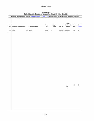
![ASME 831.3-2022
Table A-IM
Basic Allowable Stresses in Tension for Metals (SI Units) (Cont'd)
Numbers in Parentheses Refer to Notes for Tables A-1 and A-lM; Specifications Are ASTM Unless Otherwise Indicated
Basic Allowable Stress, S, MPa, at Metal Temperature, °C
[Notes (1), (2b)]
Min. Min. Min.
Min. Tensile Yield Max. Temp.
Line Temp., Strength, Strength, Temp., to
No. Notes °C (6) MPa MPa oc 40 65 100 125 150 175 200 225 250
137 (17) (32) -198 380 105 260 70.0 70.0 70.0 70.0 70.0 70.0 70.0 70.0 70.0
138 (9) -198 379 103 316 68.9 68.9 68.9 68.9 68.9 68.9 68.9 68.9 68.9
139 (9) -198 448 172 899 115 115 115 115 115 115 115 115 115
140 (9) -198 448 172 899 115 115 115 115 115 115 115 115 115
141 (9) (17) -198 450 170 899 115 115 115 115 115 115 115 115 115
142 (9) (17) -198 450 170 899 115 115 115 115 115 115 115 115 115
143 (9) -198 483 172 482 115 106 99.7 96.2 93.6 91.9 90.9 90.4 90.4
144 (17) (32) -198 483 172 482 115 106 99.7 96.2 93.6 91.9 90.9 90.4 90.4
145 (17) (32) -198 517 172 649 115 115 115 115 115 115 115 115 115
146 (17) -198 586 241 427 161 161 161 161 161 161 161 157 154
147 ... -198 586 241 427 161 161 161 161 161 161 161 157 154
148 (17) -198 517 207 816 138 138 138 138 138 138 138 138 138
149 (9) -198 517 207 816 138 138 138 138 138 138 138 138 138
150 (17) -198 552 241 427 161 161 161 161 161 161 161 161 161
151 (9) -198 552 241 427 161 161 161 161 161 161 161 161 161
152 (9) -198 552 241 649 161 161 161 161 161 161 161 161 161
153 (9) (17) -198 585 240 538 161 161 161 161 161 161 161 161 161
154 (9) -198 585 240 538 160 160 160 160 160 160 160 160 160
155 (9) -198 586 241 482 160 160 160 160 160 160 160 160 160
156 ... -198 621 276 899 184 184 184 184 184 184 184 180 175
157 ... -198 621 276 899 184 184 184 184 184 184 184 180 175
158 (32) -198 689 276 816 184 184 184 184 184 184 184 184 178
159 (17) -198 648 276 427 184 184 184 184 184 177 171 166 162
160 ... -198 648 276 427 184 184 184 184 184 177 171 166 162
161 (17) -198 689 283 677 188 188 188 188 188 188 188 188 187
162 (9) -198 689 283 677 188 188 188 188 188 188 188 188 187
163 (9) -198 689 283 677 188 188 188 188 188 188 188 188 187
164 (32) -198 689 310 427 207 207 207 207 207 207 207 207 207
165 (17) (32) -198 689 310 427 207 207 207 207 207 207 207 204 202
166 (9) -198 689 310 427 207 207 207 207 207 207 207 204 202
167 (9) -198 689 310 427 207 207 207 207 207 207 207 204 202
168 (17) (32) -198 586 241 427 161 161 161 161 161 161 154 149 144
169 (9) -198 586 241 427 161 161 161 161 161 161 154 149 144
170 (9) -198 586 241 427 161 161 161 161 161 161 154 149 144
333](https://image.slidesharecdn.com/26162943-231229160810-282cb07a/85/ASME-B31-3-2022-Procces-piping-code-for-b31-3-360-320.jpg)
![ASME 831.3-2022
Table A-IM
Basic Allowable Stresses in Tension for Metals (SI Units) (Cont'd)
Numbers in Parentheses Refer to Notes for Tables A-1 and A-lM; Specifications Are ASTM Unless Otherwise Indicated
Basic Allowable Stress, S, MPa, at Metal Temperature, °C [Notes (1), (2b)]
Line
No. 275 300 325 350 375 400 425 450 475 500 525 550 575
137 70.0
138 68.9 68.9 68.9
139 115 115 113 110 108 105 104 102 100 98.6 97.1 95.9 91.8
140 115 115 113 110 108 105 104 102 100 98.7 97.1 96.1 94.1
141 115 115 113 110 108 105 104 102 100 98.6 97.1 95.9 91.8
142 115 115 113 110 108 105 104 102 100 98.7 97.1 96.1 94.1
143 90.4 90.4 90.4 90.4 89.8 89.0 88.0 79.7 59.9 55.2
144 90.4 90.4 90.4 90.4 89.8 89.0 88.0 79.7 59.9 55.2
145 115 115 115 115 115 115 115 115 115 84.8 58.4 39.7 27.0
146 151 148 146 143 141 138 136 136
147 151 148 146 143 141 138 136 136
148 138 138 138 138 138 138 138 138 138 138 138 136 107
149 138 138 138 138 138 138 138 138 138 138 138 136 107
150 161 161 161 161 161 160 157 156
151 161 161 161 161 161 160 157 156
152 161 161 161 161 161 161 161 161 161 84.8 58.4 39.7 27.0
153 161 161 161 161 161 160 159 158 157 156 155 153
154 160 160 160 160 160 159 158 157 156 156 154 151
155 160 160 160 160 160 160 160 160 160 160
156 170 166 163 160 158 156 154 153 153 152 151 151 151
157 170 166 163 160 158 156 154 153 153 152 151 151 151
158 173 169 165 162 160 158 157 155 154 135 134 133 129
159 158 155 152 149 146 144 141 141
160 158 155 152 149 146 144 141 141
161 183 177 172 169 165 162 159 157 156 155 154 143 118
162 183 177 172 169 165 162 159 157 156 155 154 143 118
163 183 177 172 169 165 162 159 157 156 155 154 143 118
164 207 207 207 207 207 207 206 206
165 197 193 189 185 182 180 177 177
166 197 193 189 185 182 180 177 177
167 197 193 189 185 182 180 177 177
168 140 137 135 133 132 131 129 128
169 140 137 135 133 132 131 129 128
170 140 137 135 133 132 131 129 128
334](https://image.slidesharecdn.com/26162943-231229160810-282cb07a/85/ASME-B31-3-2022-Procces-piping-code-for-b31-3-361-320.jpg)
![ASME 831.3-2022
Table A-IM
Basic Allowable Stresses in Tension for Metals (SI Units) (Cont'd)
Numbers in Parentheses Refer to Notes for Tables A-1 and A-lM; Specifications Are ASTM Unless Otherwise Indicated
Basic Allowable Stress, S, MPa, at Metal Temperature, °C [Notes (1), (2b)]
Line
No. 600 625 650 675 700 725 750 775 800 825 850 875 900
137
138
139 75.7 62.6 50.6 41.2 33.6 27.7 22.6 18.3 15.0 11.9 9.03 7.35 5.86
140 85.5 69.3 56.8 46.8 38.6 31.5 25.5 20.6 17.1 13.8 10.2 7.98 6.20
141 75.7 62.6 50.6 41.2 33.6 27.7 22.6 18.3 15.0 11.9 9.03 7.35 5.86
142 85.5 69.3 56.8 46.8 38.6 31.5 25.5 20.6 17.1 13.8 10.2 7.98 6.20
143
144
145 19.2 15.0 13.8
146
147
148 83.8 63.9 44.7 29.8 15.5 11.7 8.68 7.20 6.25 5.11
149 83.8 63.9 44.7 29.8 15.5 11.7 8.68 7.20 6.25 5.11
150
151
152 19.2 15.0 13.8
153
154
155
156 117 96.2 79.3 65.6 54.4 45.0 37.2 30.6 25.1 20.5 16.5 13.0 9.8
157 117 96.2 79.3 65.6 54.4 45.0 37.2 30.6 25.1 20.5 16.5 13.0 9.8
158 115 94.2 77.3 64.9 54.7 44.7 36.1 29.2 23.6 19.1
159
160
161 99.1 81.6 67.0 54.6 42.2
162 99.1 81.6 67.0 54.6 42.2
163 99.1 81.6 67.0 54.6 42.2
164
165
166
167
168
169
170
335](https://image.slidesharecdn.com/26162943-231229160810-282cb07a/85/ASME-B31-3-2022-Procces-piping-code-for-b31-3-362-320.jpg)
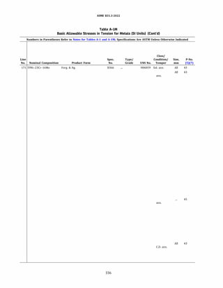
![ASME 831.3-2022
Table A-IM
Basic Allowable Stresses in Tension for Metals (SI Units) (Cont'd)
Numbers in Parentheses Refer to Notes for Tables A-1 and A-lM; Specifications Are ASTM Unless Otherwise Indicated
Basic Allowable Stress, S, MPa, at Metal Temperature, °C
[Notes (1), (2b)]
Min. Min. Min.
Min. Tensile Yield Max. Temp.
Line Temp., Strength, Strength, Temp., to
No. Notes °C (6) MPa MPa oc 40 65 100 125 150 175 200 225 250
171 (17) -198 689 310 427 207 207 207 207 207 207 207 207 206
172 ... -198 689 310 427 207 207 207 207 207 207 207 207 206
173 (17) -198 689 310 427 207 207 207 207 207 207 207 207 200
174 ... -198 689 310 427 207 207 207 207 207 207 207 207 200
175 ... -198 689 310 427 207 207 207 207 207 207 207 207 200
176 ... -198 725 310 427 207 207 207 207 207 207 204 202 199
177 ... -198 725 310 427 207 207 207 207 207 207 204 202 199
178 ... -198 725 310 427 207 207 207 207 207 207 204 202 199
179 (9) (19) -198 827 414 649 276 276 276 274 273 272 270 269 267
180 (17) -198 758 352 427 234 234 234 234 234 234 234 234 234
181 (17) -198 758 352 427 234 234 234 234 234 234 234 234 234
182 ... -198 758 352 427 234 234 234 234 234 234 234 234 234
183 ... -198 758 352 427 234 234 234 234 234 234 234 234 234
184 ... -198 758 310 899 207 207 207 207 207 207 207 207 207
185 (17) -198 758 310 899 207 207 207 207 207 207 207 207 207
186 ... -198 750 380 427 250 231 209 200 193 187 181 176 172
187 ... -198 750 380 427 250 231 209 200 193 187 181 176 172
188 ... -198 750 380 427 250 231 209 200 193 187 181 176 172
189 (9) -198 414 103 316 68.9 68.9 68.9 68.9 68.9 68.9 68.9 68.9 68.9
190 (9) -198 379 103 316 68.9 68.9 68.9 68.9 68.9 68.9 68.9 68.9 68.9
191 (13) -198 483 172 482 115 106 99.7 96.2 93.6 91.9 90.9 90.4 90.4
192 (9) -198 450 170 899 115 115 115 115 115 115 115 115 115
193 (9) -198 450 170 899 115 115 115 115 115 115 115 115 115
194 (9) -198 515 205 816 138 138 138 138 138 138 138 138 138
195 ... -198 517 193 427 129 129 129 129 129 129 129 129 129
196 ... -198 586 207 538 138 138 138 138 138 138 138 138 138
197 (9) -198 585 240 538 161 161 161 161 161 161 161 161 161
198 ... -198 585 240 482 160 160 160 160 160 160 160 160 160
199 ... -198 586 240 482 160 160 160 160 160 160 160 160 160
200 ... -198 621 241 538 161 161 161 161 161 161 161 161 161
201 ... -198 586 241 427 161 161 161 161 161 161 161 157 154
337](https://image.slidesharecdn.com/26162943-231229160810-282cb07a/85/ASME-B31-3-2022-Procces-piping-code-for-b31-3-364-320.jpg)
![ASME 831.3-2022
Table A-IM
Basic Allowable Stresses in Tension for Metals (SI Units) (Cont'd)
Numbers in Parentheses Refer to Notes for Tables A-1 and A-lM; Specifications Are ASTM Unless Otherwise Indicated
Basic Allowable Stress, S, MPa, at Metal Temperature, °C [Notes (1), (2b)]
Line
No. 275 300 325 350 375 400 425 450 475 500 525 550 575
171 202 197 192 188 184 180 176 176
172 202 197 192 188 184 180 176 176
173 194 188 184 180 177 175 174 173
174 194 188 184 180 177 175 174 173
175 194 188 184 180 177 175 174 173
176 197 193 190 188 186 184 182 180
177 197 193 190 188 186 184 182 180
178 197 193 190 188 186 184 182 180
179 265 262 260 257 255 252 251 249 247 245 242 215 194
180 234 234 234 234 234 234 234 234
181 234 234 234 234 234 233 231 230
182 234 234 234 234 234 233 231 230
183 234 234 234 234 234 233 231 230
184 207 207 203 199 197 196 195 195 195 195 195 195 183
185 207 207 203 199 197 196 195 195 195 195 195 195 183
186 169 165 163 161 159 157 156 155
187 169 165 163 161 159 157 156 155
188 169 165 163 161 159 157 156 155
189 68.9 68.9 68.9
190 68.9 68.9 68.9
191 90.4 90.4 90.4 90.4 89.8 89.0 88.0 79.7 59.9 55.2
192 115 115 113 110 108 105 104 102 100 98.6 97.1 95.9 91.8
193 115 115 113 110 108 105 104 102 100 98.7 97.1 96.1 94.1
194 138 138 138 138 138 138 138 138 138 138 137 131 108
195 129 129 127 125 122 121 119 119
196 138 135 134 132 131 130 129 128 128 127 127 126
197 161 161 161 161 161 160 159 158 157 156 155 153
198 160 160 160 160 160 160 160 160 160 160
199 160 160 160 160 160 160 160 160 160 160
200 160 158 156 154 153 152 151 150 149 136 132 130
201 151 148 146 143 141 138 136 136
338](https://image.slidesharecdn.com/26162943-231229160810-282cb07a/85/ASME-B31-3-2022-Procces-piping-code-for-b31-3-365-320.jpg)
![ASME 831.3-2022
Table A-IM
Basic Allowable Stresses in Tension for Metals (SI Units) (Cont'd)
Numbers in Parentheses Refer to Notes for Tables A-1 and A-lM; Specifications Are ASTM Unless Otherwise Indicated
Basic Allowable Stress, S, MPa, at Metal Temperature, °C [Notes (1), (2b)]
Line
No. 600 625 650 675 700 725 750 775 800 825 850 875 900
171
172
173
174
175
176
177
178
179 156 136 91.0
180
181
182
183
184 153 128 107 89.7 74.7 61.9 50.8 41.1 32.6 25.2 18.9 13.8 10.2
185 153 128 107 89.7 74.7 61.9 50.8 41.1 32.6 25.2 18.9 13.8 10.2
186
187
188
189
190
191
192 75.7 62.6 50.6 41.2 33.6 27.7 22.6 18.3 15.0 11.9 9.03 7.35 5.86
193 85.5 69.3 56.8 46.8 38.6 31.5 25.5 20.6 17.1 13.8 10.2 7.98 6.20
194 85.0 64.4 44.8 30.0 15.5 11.3 8.82 6.98 6.43 5.00
195
196
197
198
199
200
201
339](https://image.slidesharecdn.com/26162943-231229160810-282cb07a/85/ASME-B31-3-2022-Procces-piping-code-for-b31-3-366-320.jpg)
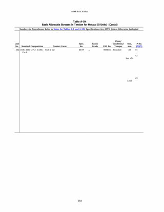
![ASME 831.3-2022
Table A-IM
Basic Allowable Stresses in Tension for Metals (SI Units) (Cont'd)
Numbers in Parentheses Refer to Notes for Tables A-1 and A-lM; Specifications Are ASTM Unless Otherwise Indicated
Basic Allowable Stress, S, MPa, at Metal Temperature, °C
[Notes (1), (2b)]
Min. Min. Min.
Min. Tensile Yield Max. Temp.
Line Temp., Strength, Strength, Temp., to
No. Notes °C (6) MPa MPa oc 40 65 100 125 150 175 200 225 250
202 ... -198 648 276 427 184 184 184 184 184 177 171 166 162
203 ... -198 552 276 510 184 182 177 174 171 168 165 164 162
204 (9) -198 586 241 427 161 161 161 161 161 161 154 149 144
205 ... -198 621 276 899 184 184 184 184 184 184 184 180 175
206 (9) -198 689 276 427 184 184 184 184 184 184 184 184 184
207 ... -198 689 283 677 188 188 188 188 188 188 188 188 187
208 ... -198 725 310 427 207 207 207 207 207 207 204 202 199
209 (9) (19) -198 758 345 649 230 230 230 230 230 230 230 230 230
(60)
210 (9) (19) -198 827 414 649 276 276 276 274 273 272 270 269 267
(60)
211 ... -198 758 310 899 207 207 207 207 207 207 207 207 207
212 ... -198 689 310 427 207 207 207 207 207 207 207 207 206
213 ... -198 689 310 427 207 207 207 207 207 207 207 207 200
214 ... -198 758 352 427 234 234 234 234 234 234 234 234 234
215 ... -198 750 380 427 250 231 209 200 193 187 181 176 172
216 (9) -198 550 310 260 184 184 184 184 184 184 184 184 184
217 (9) -198 495 275 538 165 165 165 165 165 165 165 165 165
218 (9) -198 495 275 538 165 165 165 165 165 165 165 165 165
341](https://image.slidesharecdn.com/26162943-231229160810-282cb07a/85/ASME-B31-3-2022-Procces-piping-code-for-b31-3-368-320.jpg)
![ASME 831.3-2022
Table A-IM
Basic Allowable Stresses in Tension for Metals (SI Units) (Cont'd)
Numbers in Parentheses Refer to Notes for Tables A-1 and A-lM; Specifications Are ASTM Unless Otherwise Indicated
Basic Allowable Stress, S, MPa, at Metal Temperature, °C [Notes (1), (2b)]
Line
No. 275 300 325 350 375 400 425 450 475 500 525 550 575
202 158 155 152 149 146 144 141 141
203 161 160 159 158 156 136 102 63.8 33.5 17.0 13.0
204 140 137 135 133 132 131 129 128
205 170 166 163 160 158 156 154 153 153 152 151 151 151
206 184 184 184 184 182 180 178 178
207 183 177 172 169 165 162 159 157 156 155 154 143 118
208 197 193 190 188 186 184 182 180
209 230 230 230 230 230 230 230 228 227 225 222 215 194
210 265 262 260 257 255 252 251 249 247 245 242 215 194
211 207 207 203 199 197 196 195 195 195 195 195 195 183
212 202 197 192 188 184 180 176 176
213 194 188 184 180 177 175 174 173
214 234 234 234 234 234 233 231 230
215 169 165 163 161 159 157 156 155
216 184
217 165 165 165 165 165 165 165 165 165 165 165 157
218 165 165 165 165 165 165 165 165 165 165 165 157
342](https://image.slidesharecdn.com/26162943-231229160810-282cb07a/85/ASME-B31-3-2022-Procces-piping-code-for-b31-3-369-320.jpg)
![ASME 831.3-2022
Table A-IM
Basic Allowable Stresses in Tension for Metals (SI Units) (Cont'd)
Numbers in Parentheses Refer to Notes for Tables A-1 and A-lM; Specifications Are ASTM Unless Otherwise Indicated
Basic Allowable Stress, S, MPa, at Metal Temperature, °C [Notes (1), (2b)]
Line
No. 600 625 650 675 700 725 750 775 800 825 850 875 900
202
203
204
205 117 96.2 79.3 65.6 54.4 45.0 37.2 30.6 25.1 20.5 16.5 13.0 9.8
206
207 99.1 81.6 67.0 54.6 42.2
208
209 156 136 91.0
210 156 136 91.0
211 153 128 107 89.7 74.7 61.9 50.8 41.1 32.6 25.2 18.9 13.8 10.2
212
213
214
215
216
217
218
343](https://image.slidesharecdn.com/26162943-231229160810-282cb07a/85/ASME-B31-3-2022-Procces-piping-code-for-b31-3-370-320.jpg)
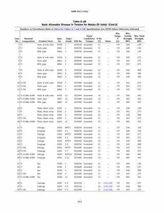
![ASME 831.3-2022
Table A-IM
Basic Allowable Stresses in Tension for Metals (SI Units) (Cont'd)
Numbers in Parentheses Refer to Notes for Tables A-1 and A-lM; Specifications Are ASTM Unless Otherwise Indicated
Basic Allowable Stress, S, MPa, at Metal Temperature, °C (Notes (1), (2b)]
Max. Min.
Line Temp., Temp. to
No. oc 40 65 100 125 150 175 200 225 250 275 300 325
1 316 80.3 73.8 62.4 55.5 49.4 43.4 38.3 33.9 30.2 27.3 25.2 23.7
2 316 80.3 73.8 62.4 55.5 49.4 43.4 38.3 33.9 30.2 27.3 25.2 23.7
3 316 80.3 73.8 62.4 55.5 49.4 43.4 38.3 33.9 30.2 27.3 25.2 23.7
4 316 115 108 98.3 90.7 83.0 77.5 72.0 67.3 62.7 58.7 54.7 50.7
5 316 115 108 98.3 90.7 83.0 77.5 72.0 67.3 62.7 58.7 54.7 50.7
6 316 115 108 98.3 90.7 83.0 77.5 72.0 67.3 62.7 58.7 54.7 50.7
7 316 149 139 124 113 102 93.3 84.7 77.7 70.7 66.2 61.7 57.7
8 316 149 139 124 113 102 93.3 84.7 77.7 70.7 66.2 61.7 57.7
9 316 149 139 124 113 102 93.3 84.7 77.7 70.7 66.2 61.7 57.7
10 316 115 108 98.3 90.7 83.0 77.5 72.0 67.3 62.7 58.7 54.7 50.7
11 316 115 108 98.3 90.7 83.0 77.5 72.0 67.3 62.7 58.7 54.7 50.7
12 316 115 108 98.3 90.7 83.0 77.5 72.0 67.3 62.7 58.7 54.7 50.7
13 316 161 156 148 139 130 123 116 111 106 104 101 98.3
14 316 161 156 148 139 130 123 116 111 106 104 101 98.3
15 316 161 156 148 139 130 123 116 111 106 104 101 98.3
16 316 80.3 73.8 62.4 55.5 49.4 43.4 38.3 33.9 30.2 27.3 25.2 23.7
17 316 115 108 98.3 90.7 83.0 77.5 72.0 67.3 62.7 58.7 54.7 50.7
18 316 149 139 124 113 102 93.3 84.7 77.7 70.7 66.2 61.7 57.7
19 316 115 108 98.3 90.7 83.0 77.5 72.0 67.3 62.7 58.7 54.7 50.7
20 316 161 156 148 139 130 123 116 111 106 104 101 98.3
21 316 80.3 73.8 62.4 55.5 49.4 43.4 38.3 33.9 30.2 27.3 25.2 23.7
22 316 80.3 73.8 62.4 55.5 49.4 43.4 38.3 33.9 30.2 27.3 25.2 23.7
23 316 115 108 98.3 90.7 83.0 77.5 72.0 67.3 62.7 58.7 54.7 50.7
24 316 115 108 98.3 90.7 83.0 77.5 72.0 67.3 62.7 58.7 54.7 50.7
25 316 149 139 124 113 102 93.3 84.7 77.7 70.7 66.2 61.7 57.7
26 316 149 139 124 113 102 93.3 84.7 77.7 70.7 66.2 61.7 57.7
27 316 115 108 98.3 90.7 83.0 77.5 72.0 67.3 62.7 58.7 54.7 50.7
28 316 115 108 98.3 90.7 83.0 77.5 72.0 67.3 62.7 58.7 54.7 50.7
29 316 161 156 148 139 130 123 116 111 106 104 101 98.3
30 316 161 156 148 139 130 123 116 111 106 104 101 98.3
31 316 80.3 73.8 62.4 55.5 49.4 43.4 38.3 33.9 30.2 27.3 25.2 23.7
32 316 115 108 98.3 90.7 83.0 77.5 72.0 67.3 62.7 58.7 54.7 50.7
33 316 149 139 124 113 102 93.3 84.7 77.7 70.7 66.2 61.7 57.7
34 316 115 108 98.3 90.7 83.0 77.5 72.0 67.3 62.7 58.7 54.7 50.7
35 316 161 156 148 139 130 123 116 111 106 104 101 98.3
36 260 115 106 92.7 85.3 78.0 72.2 66.3 61.5 56.7 52.0
37 260 149 139 124 113 102 93.3 84.7 77.7 70.7 65.3
38 260 115 106 92.7 85.3 78.0 72.2 66.3 61.5 56.7 52.0
345](https://image.slidesharecdn.com/26162943-231229160810-282cb07a/85/ASME-B31-3-2022-Procces-piping-code-for-b31-3-372-320.jpg)
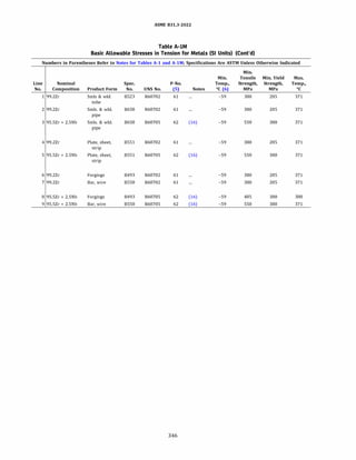
![ASME 831.3-2022
Table A-IM
Basic Allowable Stresses in Tension for Metals (SI Units) (Cont'd)
Numbers in Parentheses Refer to Notes for Tables A-1 and A-lM; Specifications Are ASTM Unless Otherwise Indicated
Basic Allowable Stress, S, MPa, at Metal Temperature, °C [Notes (1), (2b)]
Min.
Line Temp.
No. to 40 65 100 125 150 175 200 225 250 275 300 325 350 375
1 126 119 103 92.4 82.5 73.6 65.7 58.8 52.8 47.8 43.7 40.4 37.8 36.1
2 126 119 103 92.4 82.5 73.6 65.7 58.8 52.8 47.8 43.7 40.4 37.8 36.1
3 184 169 149 139 130 123 116 111 106 101 97.6 94.6 92.4 91.0
4 126 119 103 92.4 82.5 73.6 65.7 58.8 52.8 47.8 43.7 40.4 37.8 36.1
5 184 169 149 139 130 123 116 111 106 101 97.6 94.6 92.4 91.0
6 126 119 103 92.4 82.5 73.6 65.7 58.8 52.8 47.8 43.7 40.4 37.8 36.1
7 126 119 103 92.4 82.5 73.6 65.7 58.8 52.8 47.8 43.7 40.4 37.8 36.1
8 161 148 130 122 114 108 101 97.1 92.7 88.4 85.4 82.8 80.8 79.6
9 184 169 149 139 130 123 116 111 106 101 97.6 94.6 92.4 91.0
347](https://image.slidesharecdn.com/26162943-231229160810-282cb07a/85/ASME-B31-3-2022-Procces-piping-code-for-b31-3-374-320.jpg)
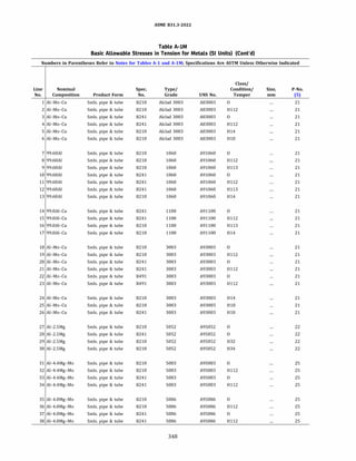
![ASME 831.3-2022
Table A-IM
Basic Allowable Stresses in Tension for Metals (SI Units) (Cont'd)
Numbers in Parentheses Refer to Notes for Tables A-1 and A-lM; Specifications Are ASTM Unless Otherwise Indicated
Basic Allowable Stress, S, MPa, at Metal Temperature, °C
Min. [Notes (1), (2b)]
Min. Tensile Min.Yield Max. Min.
Line Temp., Strength, Strength, Temp., Temp.
No. Notes 0
( (6) MPa MPa oc to 40 65 100 125 150 175 200 225
1 (14) (33) -269 90 31 204 20.7 19.9 19.3 18.4 17.3 13.6 10.9 10.5
2 (14) (33) -269 90 31 204 20.7 19.9 19.3 18.4 17.3 13.6 10.9 10.5
3 (14) (33) -269 90 31 204 20.7 19.9 19.3 18.4 17.3 13.6 10.9 10.5
4 (14) (33) -269 90 31 204 20.7 19.9 19.3 18.4 17.3 13.6 10.9 10.5
5 (14) (33) -269 131 110 204 43.7 43.7 43.7 41.7 29.0 21.1 16.7 16.1
6 (14) (33) -269 179 159 204 59.8 59.8 59.8 57.0 29.0 21.1 16.7 16.1
7 (14) (33) -269 59 17 204 11.5 11.5 10.9 9.8 8.8 7.5 5.8 5.5
8 (14) (33) -269 59 17 204 11.5 11.5 10.9 9.8 8.8 7.5 5.8 5.5
9 (14) (33) -269 59 17 204 11.5 11.5 10.9 9.8 8.8 7.5 5.8 5.5
10 (14) (33) -269 59 17 204 11.5 11.5 10.9 9.8 8.8 7.5 5.8 5.5
11 (14) (33) -269 59 17 204 11.5 11.5 10.9 9.8 8.8 7.5 5.8 5.5
12 (14) (33) -269 59 17 204 11.5 11.5 10.9 9.8 8.8 7.5 5.8 5.5
13 (14) (33) -269 83 69 204 27.6 27.6 27.6 26.6 18.1 12.7 8.4 7.8
14 (14) (33) -269 76 21 204 13.8 13.8 13.7 13.2 11.8 9.3 7.2 6.9
15 (14) (33) -269 76 21 204 13.8 13.8 13.7 13.2 11.8 9.3 7.2 6.9
16 (14) (33) -269 76 24 204 16.1 16.1 16.0 15.6 11.8 9.3 7.2 6.9
17 (14) (33) -269 110 97 204 36.8 36.8 36.1 33.1 19.0 13.6 8.5 7.8
18 (14) (33) -269 97 34 204 23.0 22.1 21.4 20.5 18.2 13.6 10.9 10.5
19 (14) (33) -269 97 34 204 23.0 22.1 21.4 20.5 18.2 13.6 10.9 10.5
20 (14) (33) -269 97 34 204 23.0 22.1 21.4 20.5 18.2 13.6 10.9 10.5
21 (14) (33) -269 97 34 204 23.0 22.1 21.4 20.5 18.2 13.6 10.9 10.5
22 (14) (33) -269 97 34 204 23.0 22.1 21.4 20.5 18.2 13.6 10.9 10.5
23 (14) (33) -269 97 34 204 23.0 22.1 21.4 20.5 18.2 13.6 10.9 10.5
24 (14) (33) -269 138 117 204 46.0 46.0 46.0 43.9 29.0 21.1 16.7 16.1
25 (14) (33) -269 186 165 204 62.1 62.1 60.3 52.1 36.1 24.5 18.0 17.0
26 (14) (33) -269 186 165 204 62.1 62.1 60.3 52.1 36.1 24.5 18.0 17.0
27 (14) -269 172 69 204 46.0 46.0 46.0 45.9 41.6 28.8 17.6 16.1
28 (14) -269 172 69 204 46.0 46.0 46.0 45.9 41.6 28.8 17.6 16.1
29 (14) (33) -269 214 159 204 71.2 71.2 71.2 71.0 41.6 28.8 17.6 16.1
30 (14) (33) -269 234 179 204 78.1 78.1 78.1 78.1 41.6 28.8 17.6 16.1
31 (33) -269 269 110 65 73.5 73.5
32 (33) -269 269 110 65 73.5 73.5
33 (33) -269 269 110 65 73.5 73.5
34 (33) -269 269 110 65 73.5 73.5
35 (33) -269 241 97 65 64.4 64.4
36 (33) -269 241 97 65 64.4 64.4
37 (33) -269 241 97 65 64.4 64.4
38 (33) -269 241 97 65 64.4 64.4
349](https://image.slidesharecdn.com/26162943-231229160810-282cb07a/85/ASME-B31-3-2022-Procces-piping-code-for-b31-3-376-320.jpg)
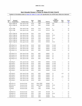
![ASME 831.3-2022
Table A-IM
Basic Allowable Stresses in Tension for Metals (SI Units) (Cont'd)
Numbers in Parentheses Refer to Notes for Tables A-1 and A-lM; Specifications Are ASTM Unless Otherwise Indicated
Basic Allowable Stress, S, MPa, at Metal Temperature, °C
Min. [Notes (1), (2b)]
Min. Tensile Min.Yield Max. Min.
Line Temp., Strength, Strength, Temp., Temp.
No. Notes 0
( (6) MPa MPa oc to 40 65 100 125 150 175 200 225
39 (33) -269 276 193 65 91.9 91.9
40 (33) -269 303 234 65 101.1 101.1
41 ... -269 207 76 65 50.6 50.6
42 (33) -269 269 200 65 89.6 89.6
43 (33) -269 214 83 204 55.2 55.2 55.2 48.9 37.5 28.6 21.7 20.7
44 (33) -269 214 83 204 55.2 55.2 55.2 48.9 37.5 28.6 21.7 20.7
45 (33) -269 283 131 65 87.3 87.3
46 (33) -269 283 131 65 87.3 87.3
47 (33) -269 283 131 65 87.3 87.3
48 (33) -269 283 131 65 87.3 87.3
49 (22) (44) -269 165 204 55.2 55.2 55.2 54.3 52.0 46.3 35.3 34.8
so (22) (44) -269 165 204 55.2 55.2 55.2 54.3 52.0 46.3 35.3 34.8
51 (22) (44) -269 165 204 55.2 55.2 55.2 54.3 52.0 46.3 35.3 34.8
52 (22) (44) -269 165 204 55.2 55.2 55.2 54.3 52.0 46.3 35.3 34.8
53 (33) (44) -269 179 110 204 59.8 59.8 59.8 58.9 56.3 50.2 38.3 35.9
54 (33) -269 207 110 204 68.9 68.9 68.9 67.8 64.8 57.9 40.2 35.9
55 (33) (44) -269 262 241 204 87.3 87.3 87.3 83.6 72.3 57.2 40.2 35.9
56 (33) -269 290 241 204 96.5 96.5 96.5 92.5 79.9 63.1 40.2 35.9
57 ... -269 117 204 39.1 39.1 37.9 35.9 32.1 25.7 17.6 13.8
58 ... -269 117 204 39.1 39.1 37.9 35.9 32.1 25.7 17.6 13.8
59 ... -269 117 204 39.1 39.1 37.9 35.9 32.1 25.7 17.6 13.8
60 ... -269 117 204 39.1 39.1 37.9 35.9 32.1 25.7 17.6 13.8
61 ... -269 117 204 39.1 39.1 37.9 35.9 32.1 25.7 17.6 13.8
62 ... -269 117 204 39.1 39.1 37.9 35.9 32.1 25.7 17.6 13.8
63 (33) -269 131 69 204 43.7 43.7 43.7 43.7 43.7 35.8 23.9 10.3
64 (33) -269 152 69 204 46.0 45.8 45.8 45.5 45.5 41.5 27.7 12.0
65 (33) -269 152 110 204 50.6 50.6 48.7 46.6 41.4 27.5 15.3 13.8
66 (33) -269 207 172 204 68.9 68.9 67.7 59.0 45.9 27.5 15.3 49.3
67 (33) -269 228 193 204 75.8 75.8 74.8 64.0 49.2 27.5 15.3 13.8
68 (33) (42) -269 90 31 204 20.7 19.9 19.3 18.4 17.3 13.6 10.9 10.5
69 (33) (42) -269 90 31 204 20.7 19.9 19.3 18.4 17.3 13.6 10.9 10.5
70 (33) (42) -269 59 17 204 11.5 11.5 10.9 9.8 8.8 7.5 5.8 5.5
71 (33) (42) -269 59 17 204 11.5 11.5 10.9 9.8 8.8 7.5 5.8 5.5
72 (33) (42) -269 76 21 204 13.8 13.8 13.7 13.2 11.8 9.3 7.2 6.9
73 (33) (42) -269 76 21](https://image.slidesharecdn.com/26162943-231229160810-282cb07a/85/ASME-B31-3-2022-Procces-piping-code-for-b31-3-378-320.jpg)
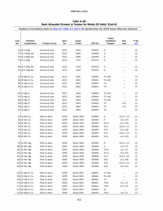
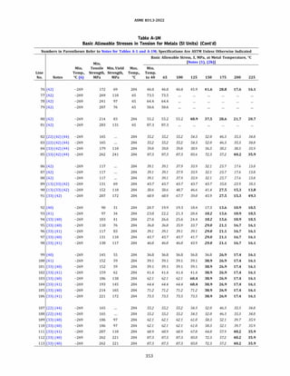
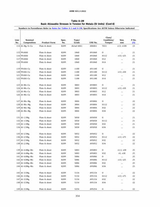
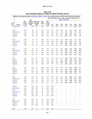
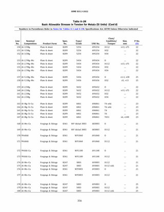
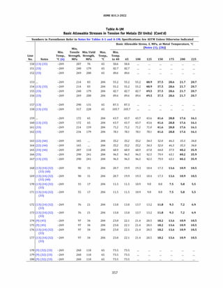
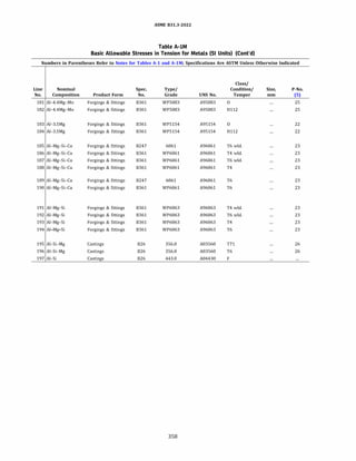
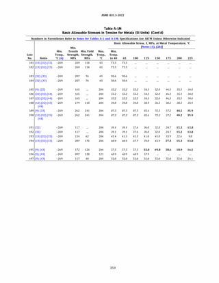
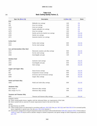
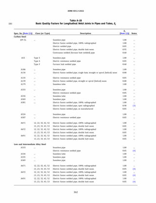
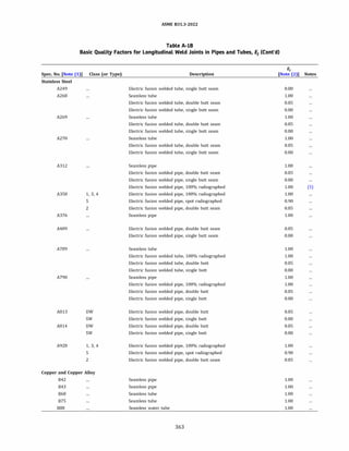
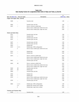
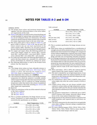

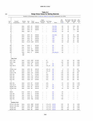
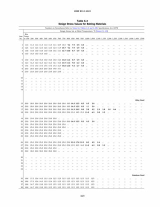
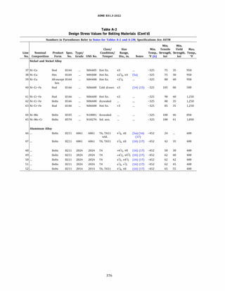
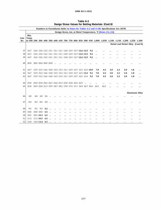
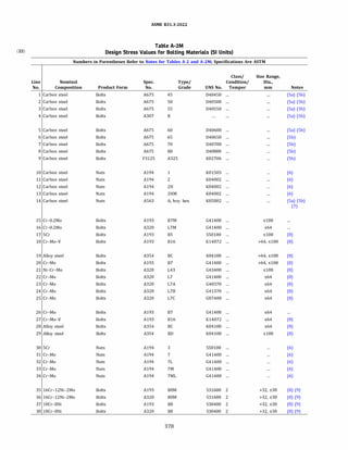
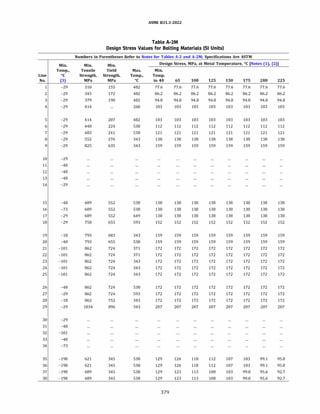
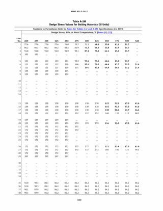
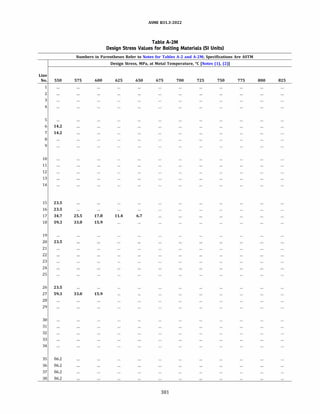
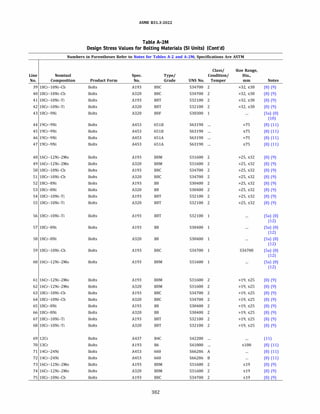
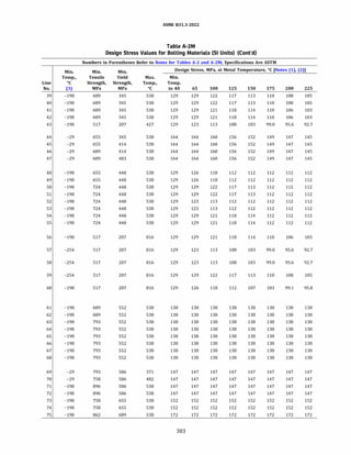
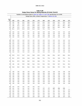
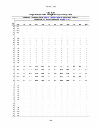
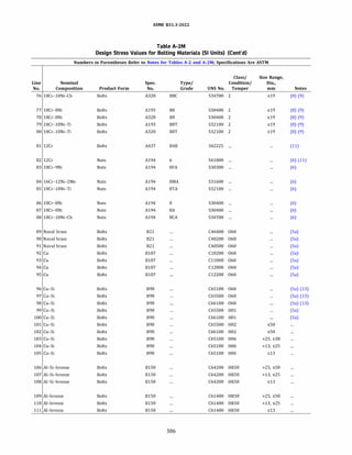
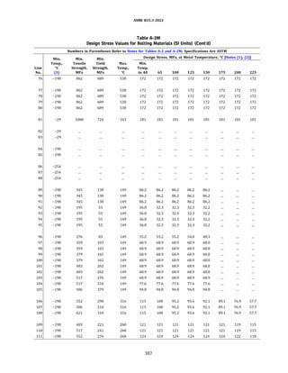
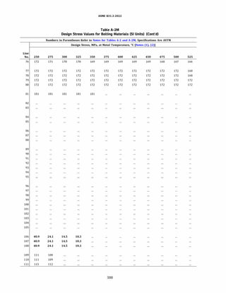
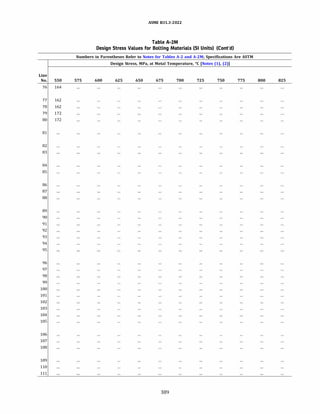
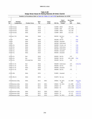
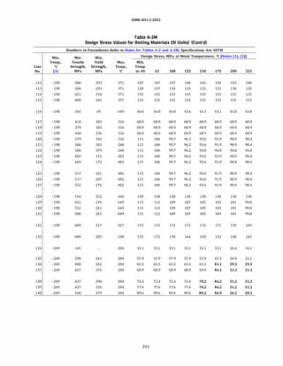
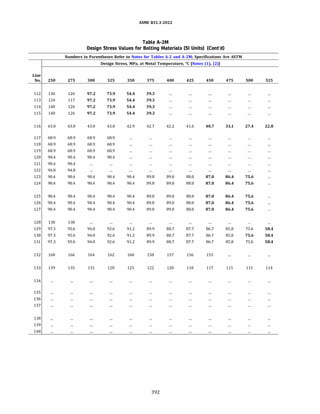
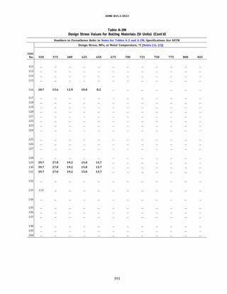
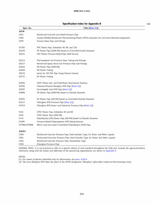
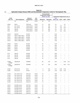
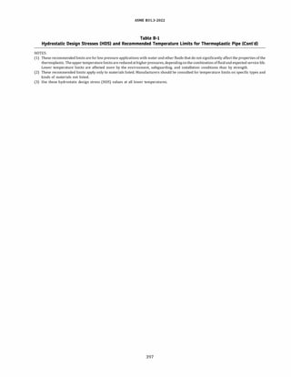
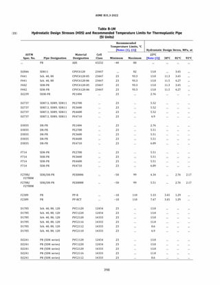
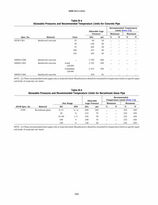
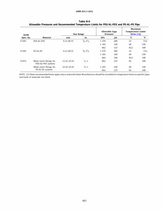
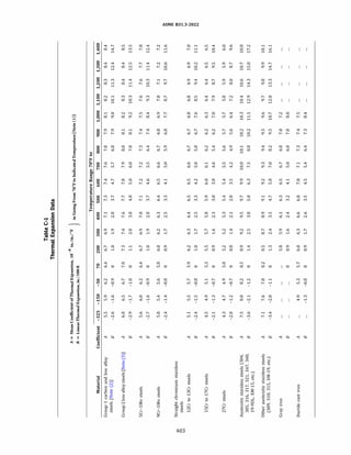
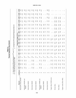
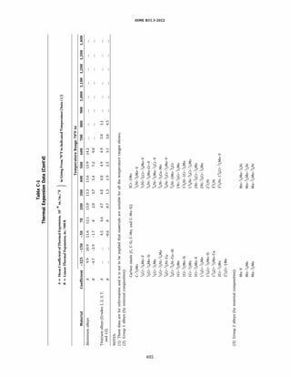
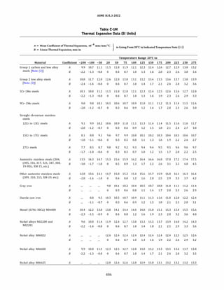
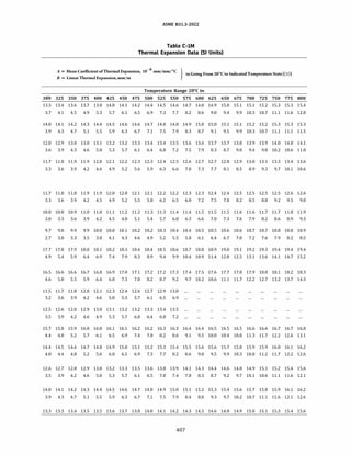
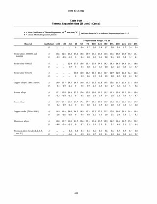
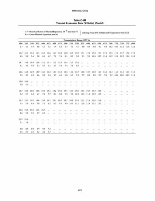
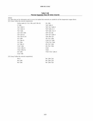
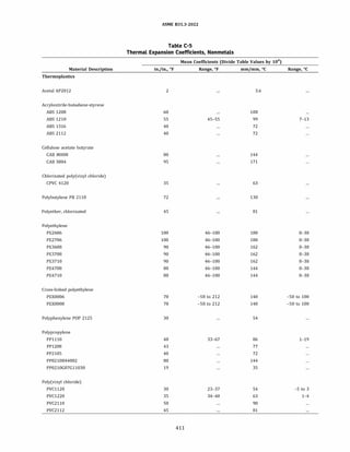
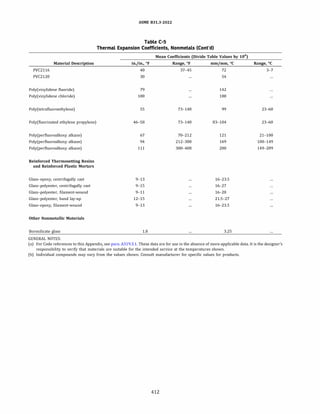
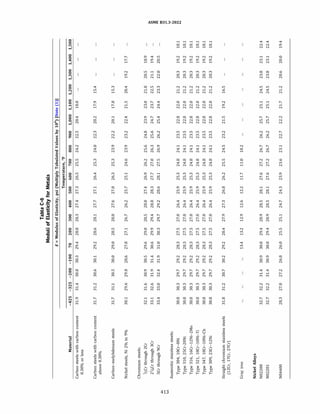
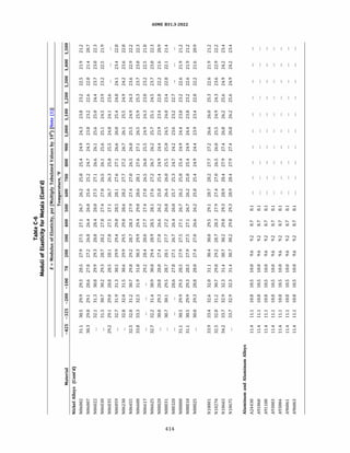
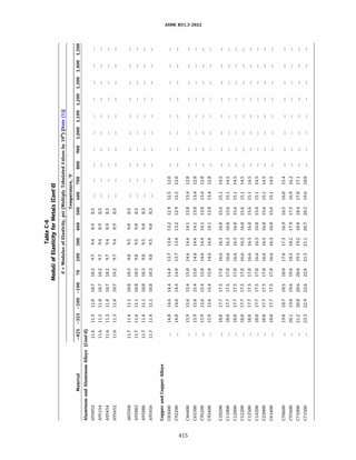
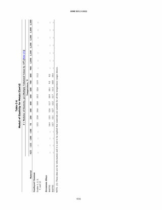
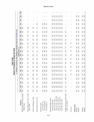
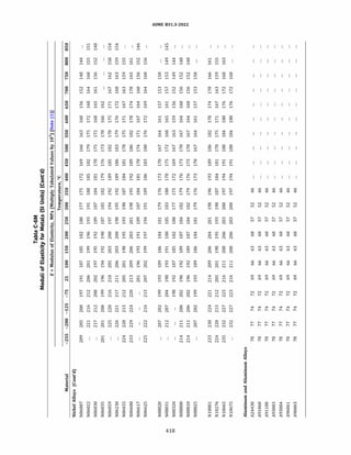
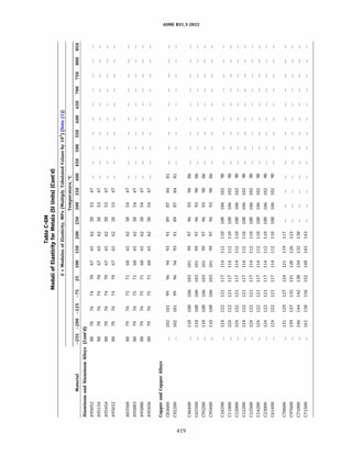

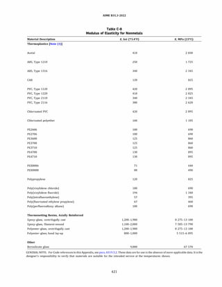

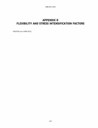
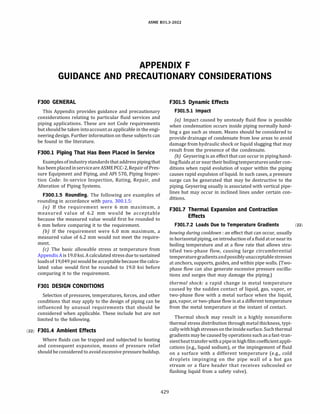
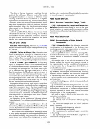
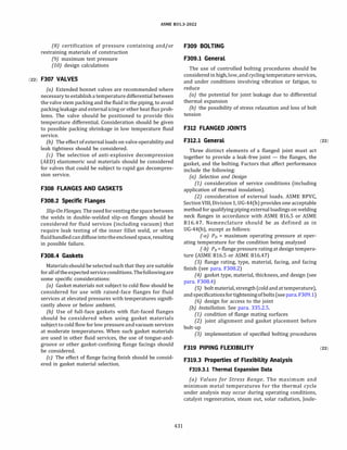
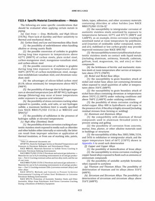
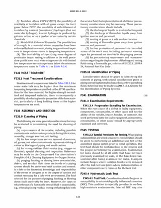
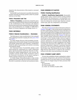

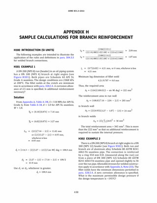
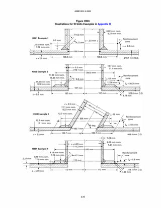
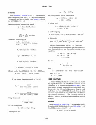
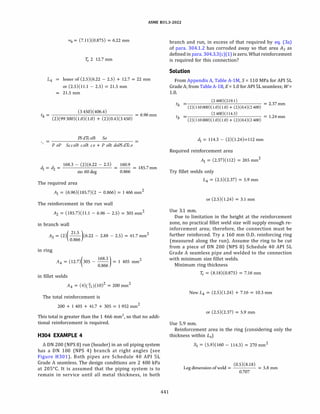
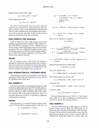
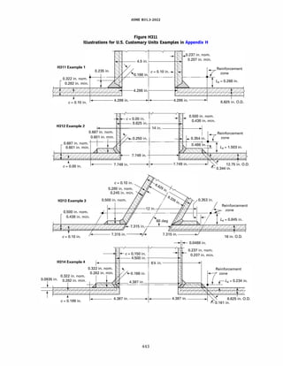
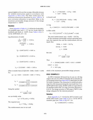
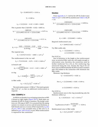

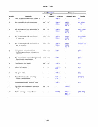
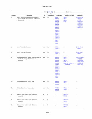
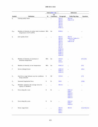
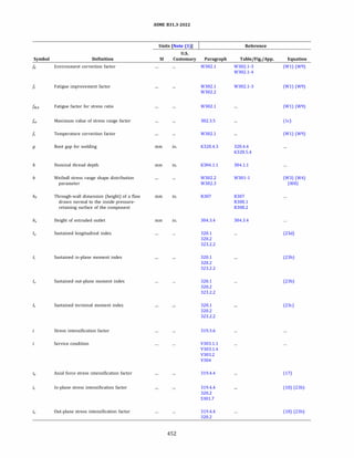
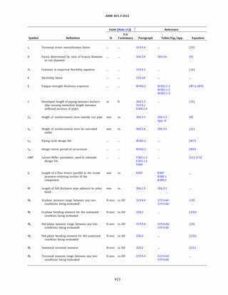
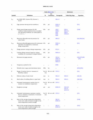
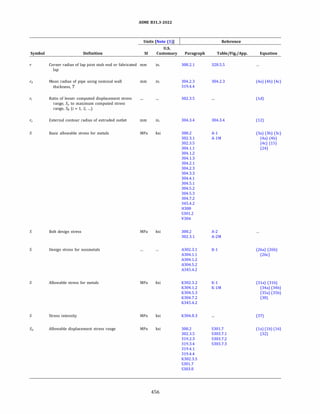
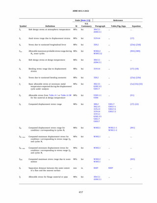
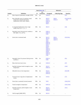
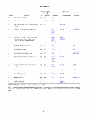
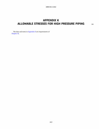
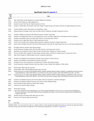
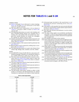
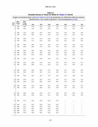
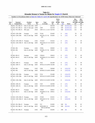
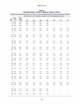
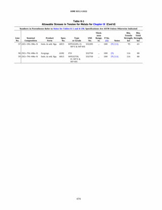
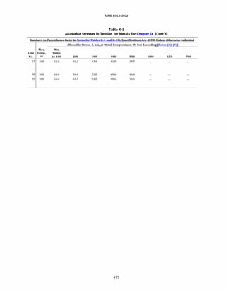
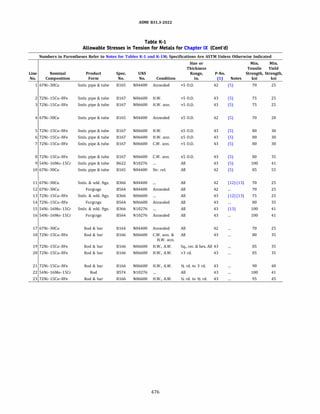
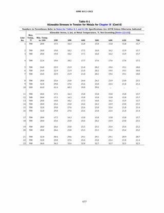
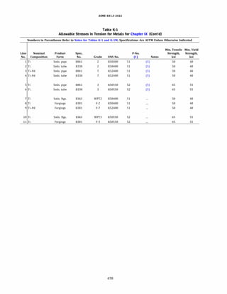
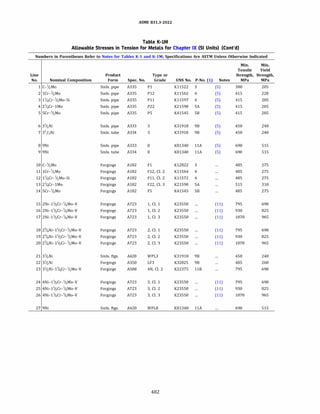
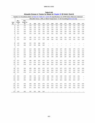
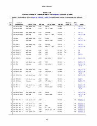
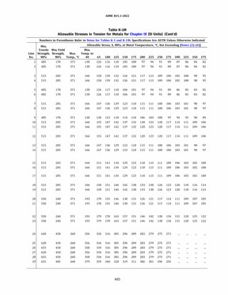
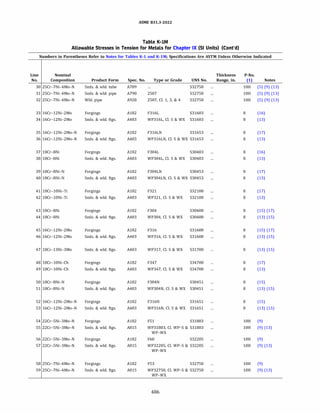
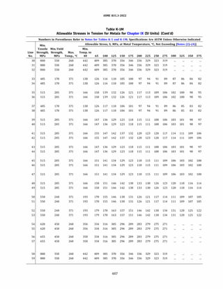
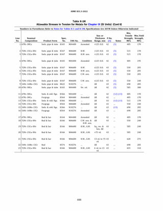
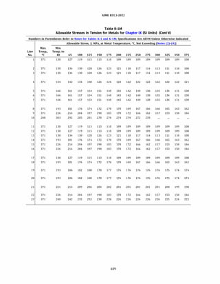
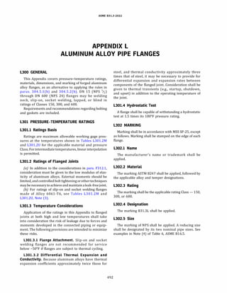
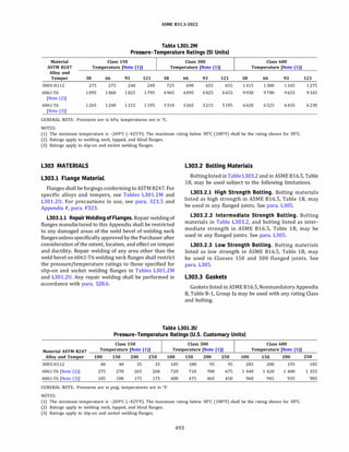
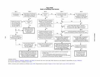

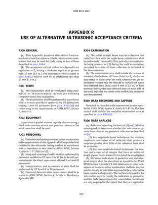
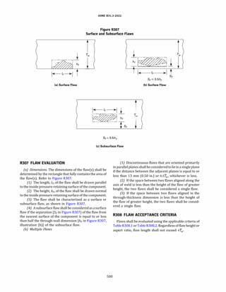
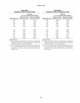
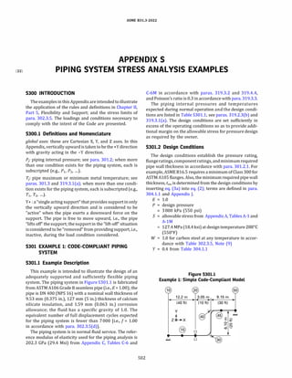
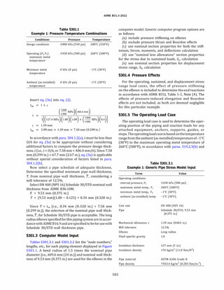
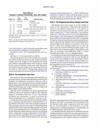
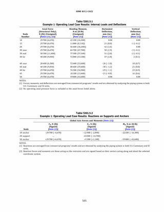
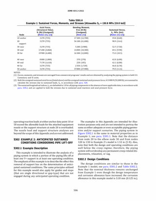
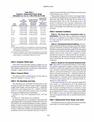
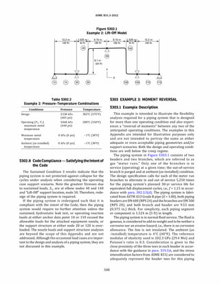
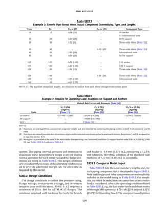
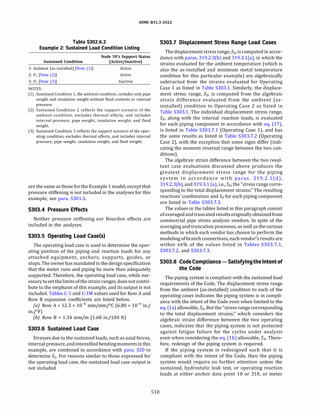
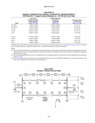
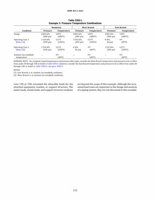
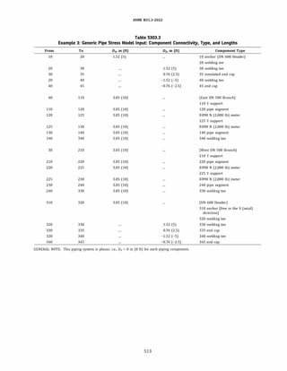
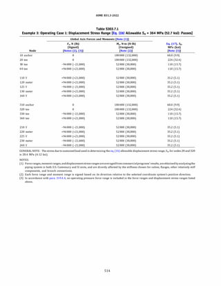
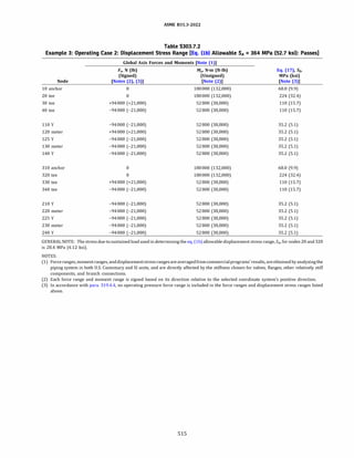
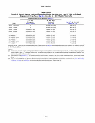
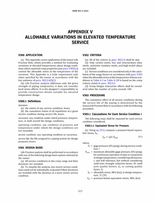
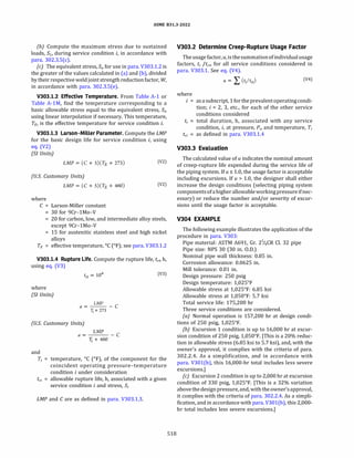
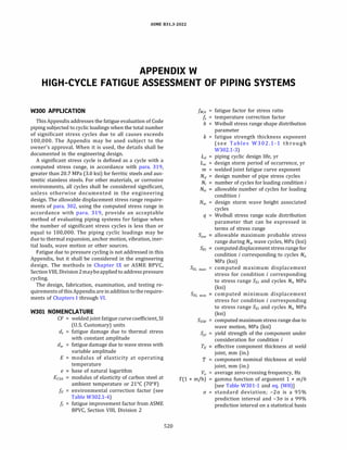
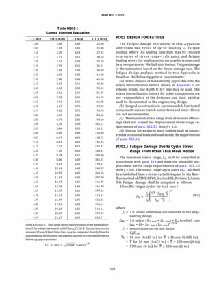
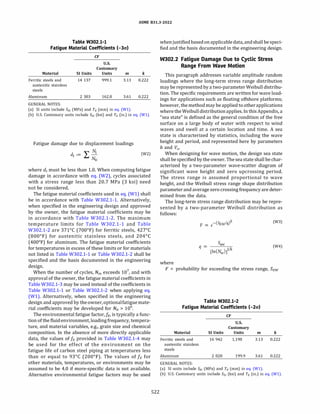
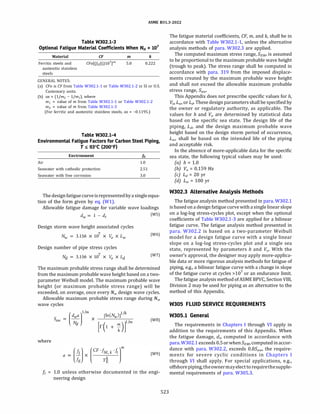
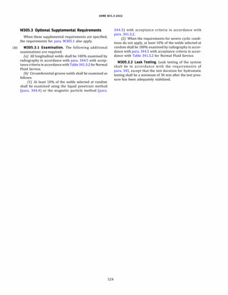
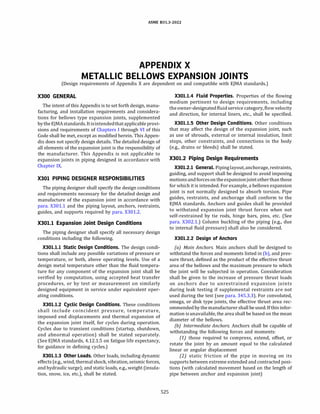
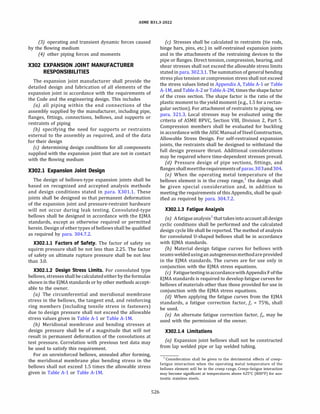

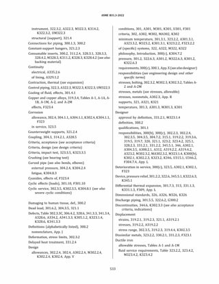
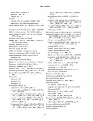
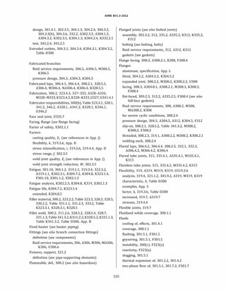
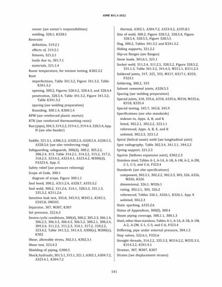
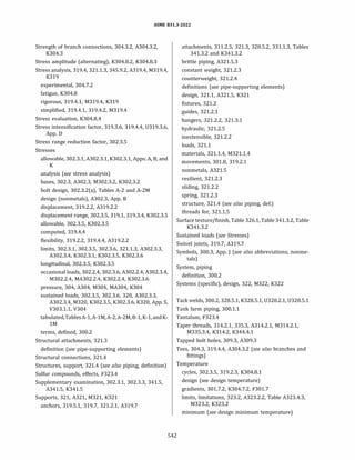
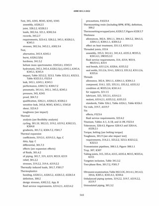
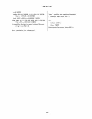
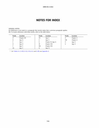
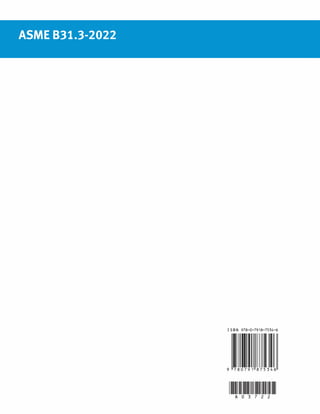


![[Point] pipe stress analysis by computer-caesar ii](https://cdn.slidesharecdn.com/ss_thumbnails/point-pipestressanalysisbycomputer-caesarii-150407122607-conversion-gate01-thumbnail.jpg?width=640&height=640&fit=bounds)


