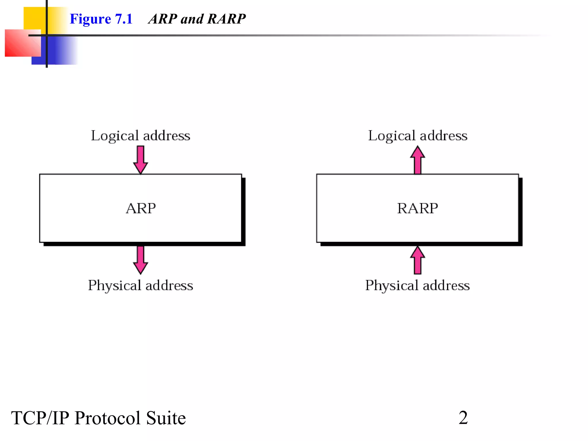
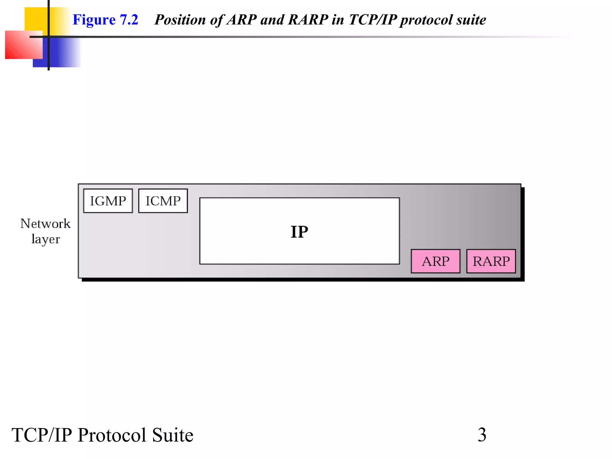
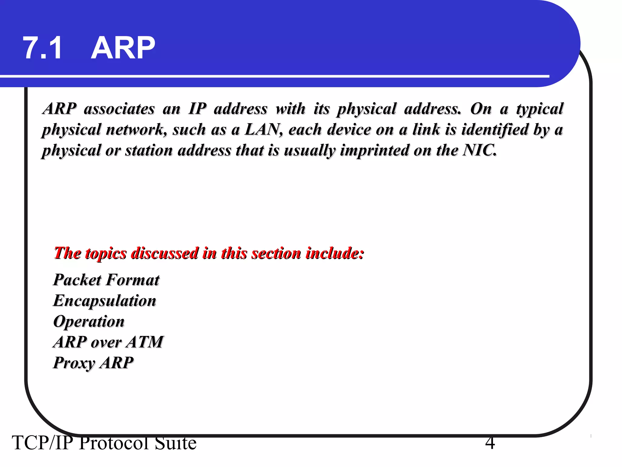
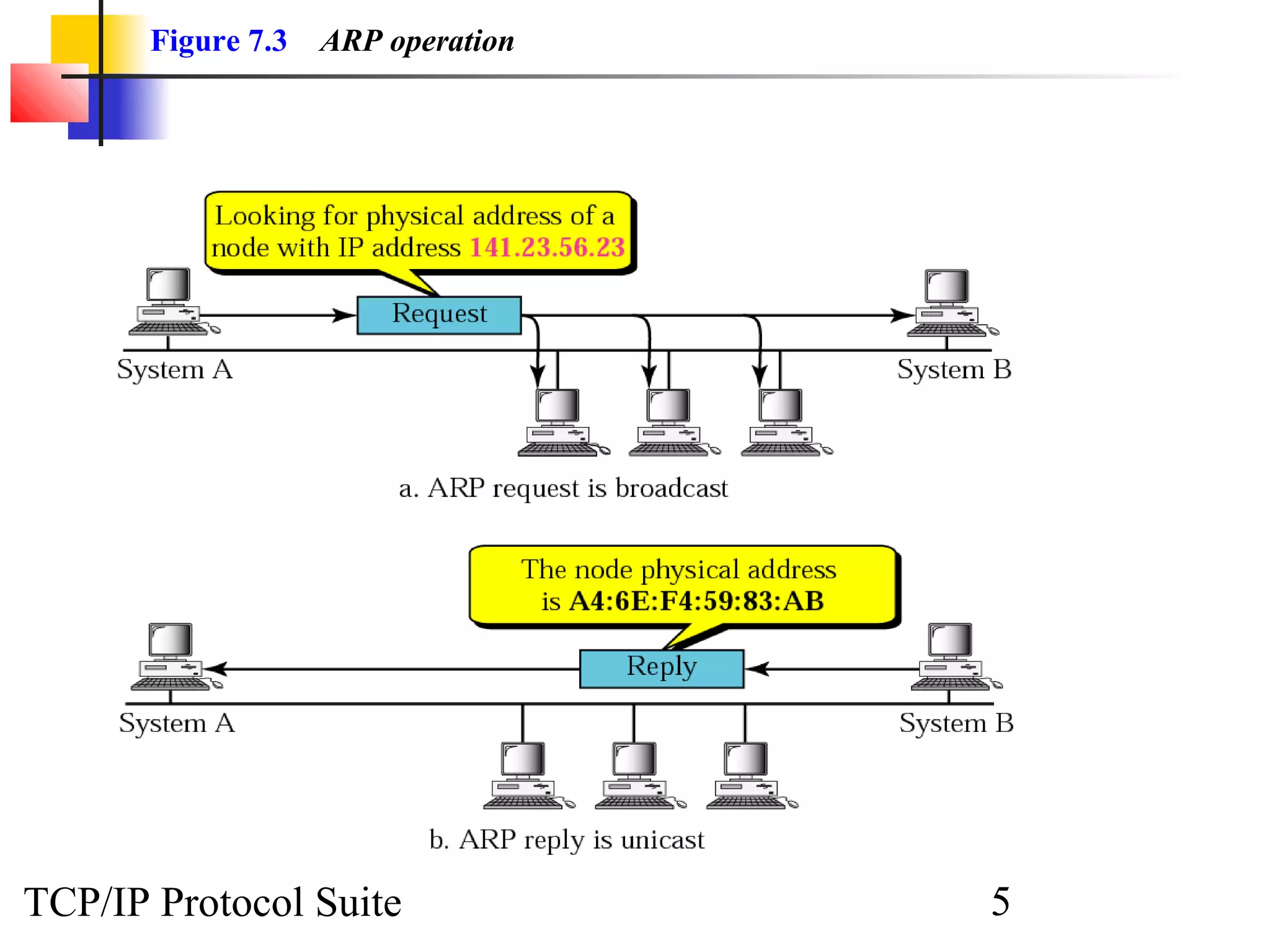
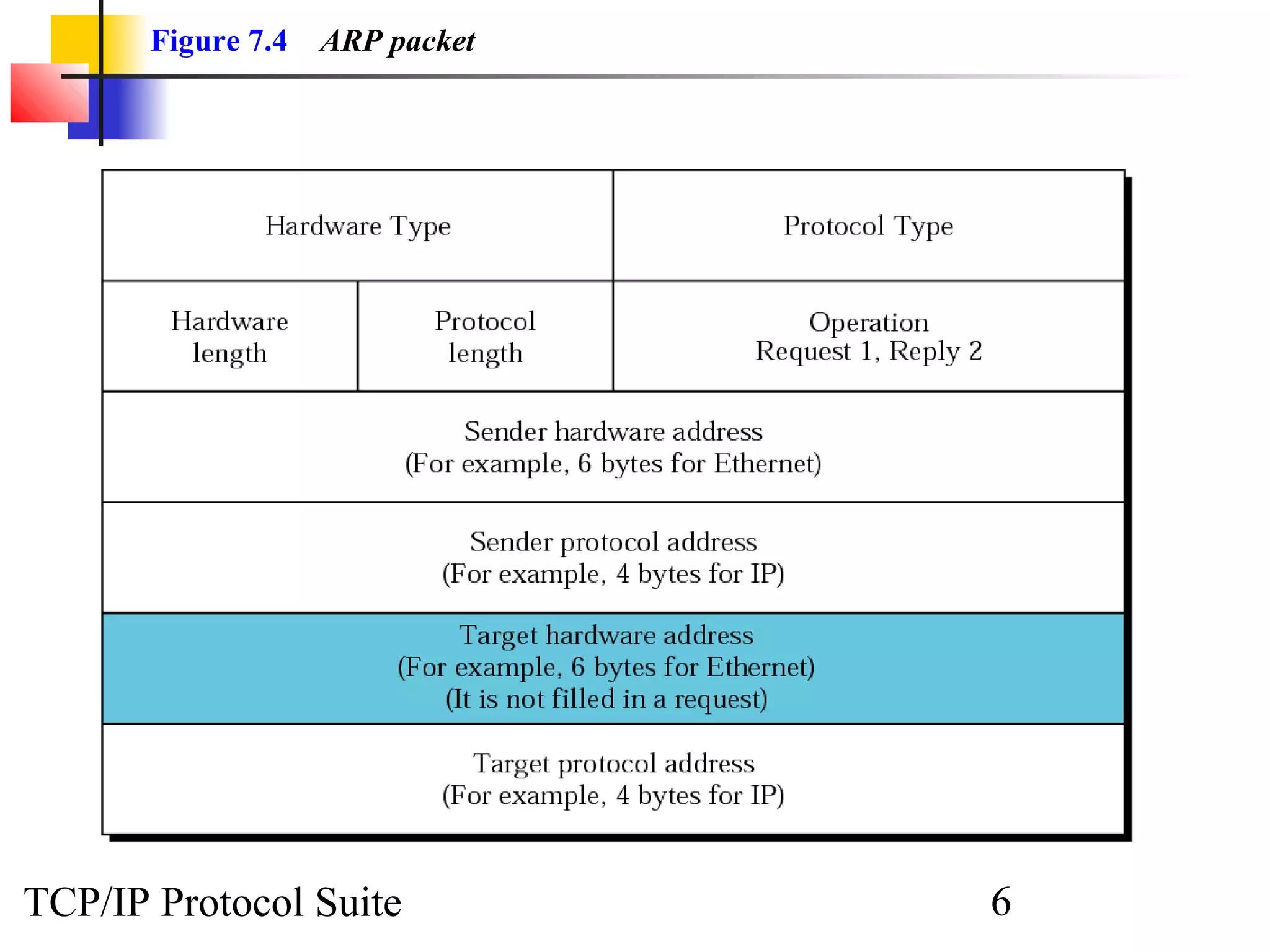
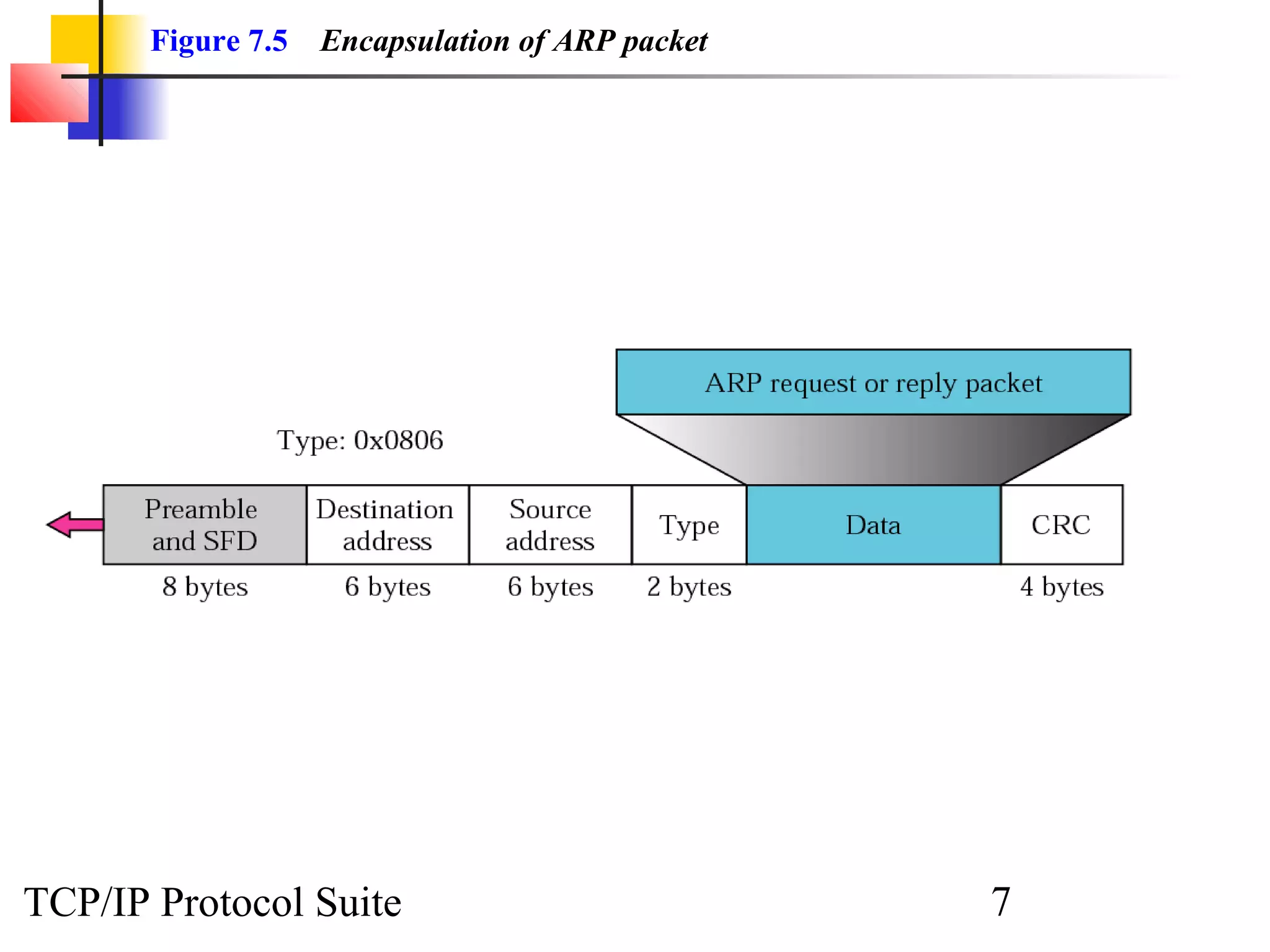
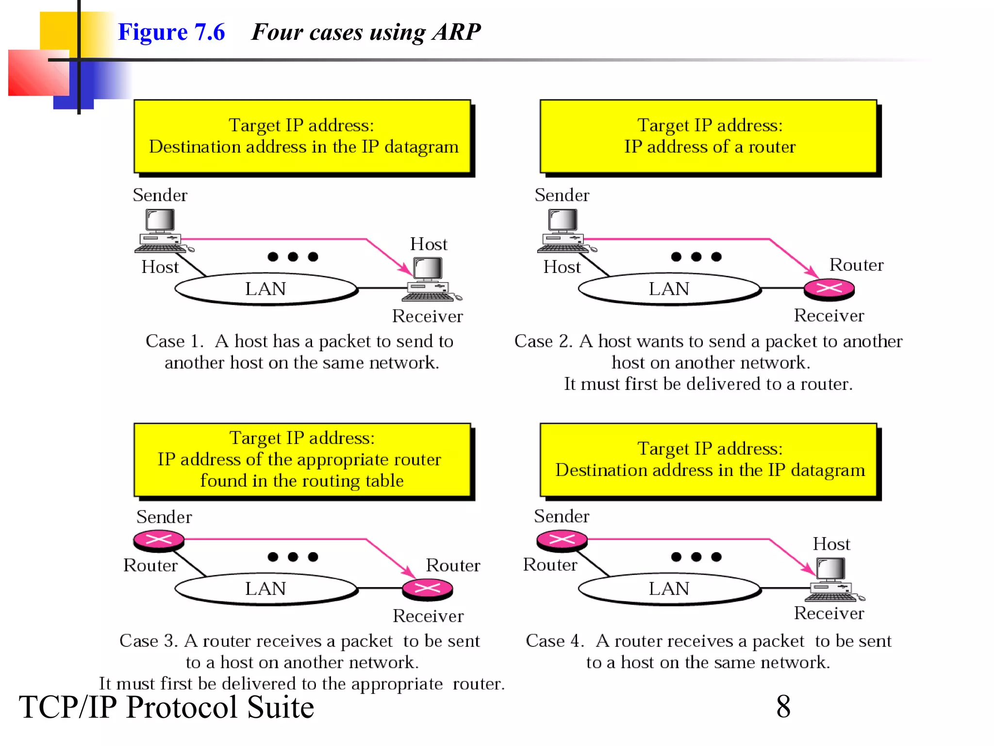
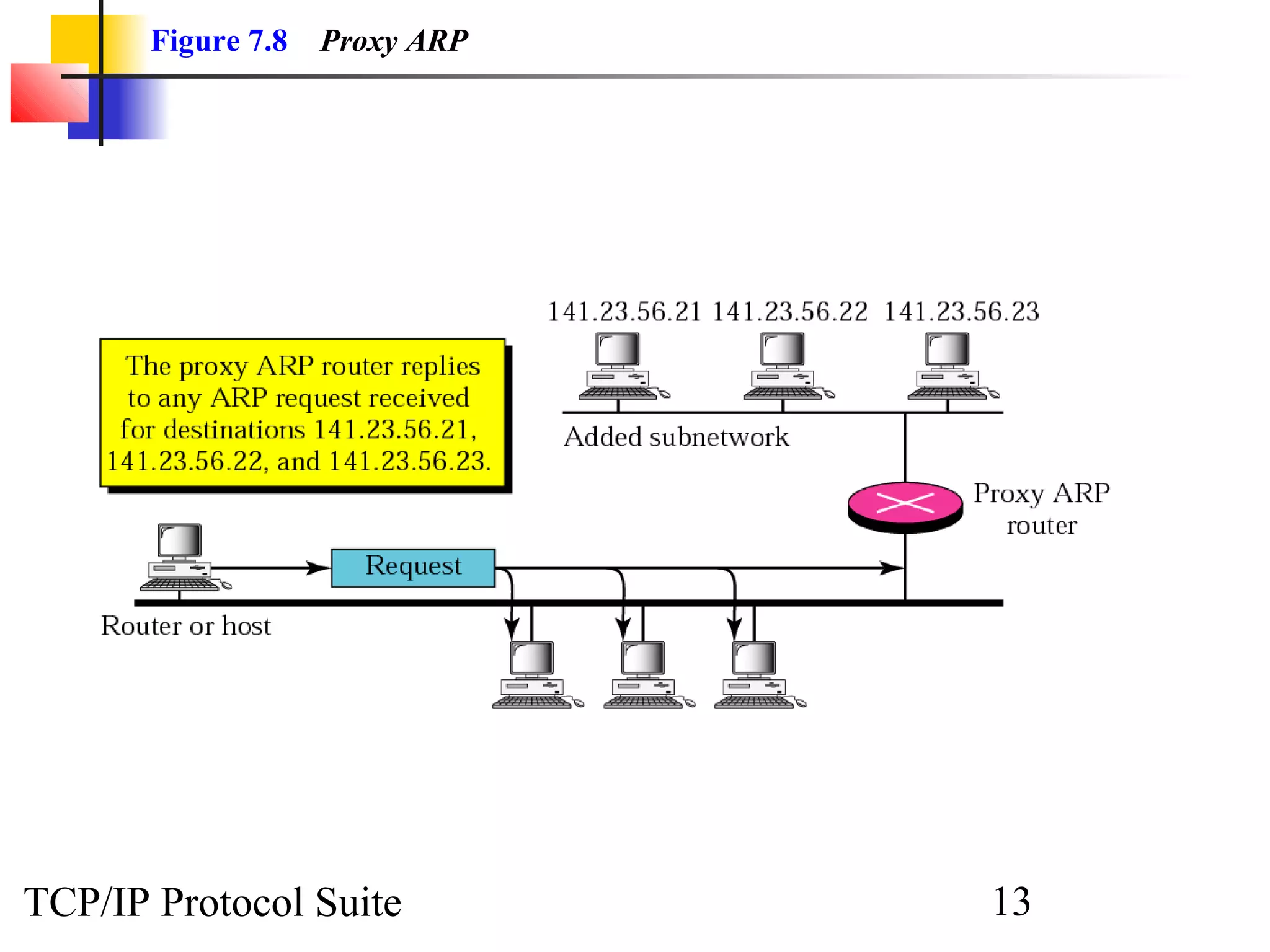
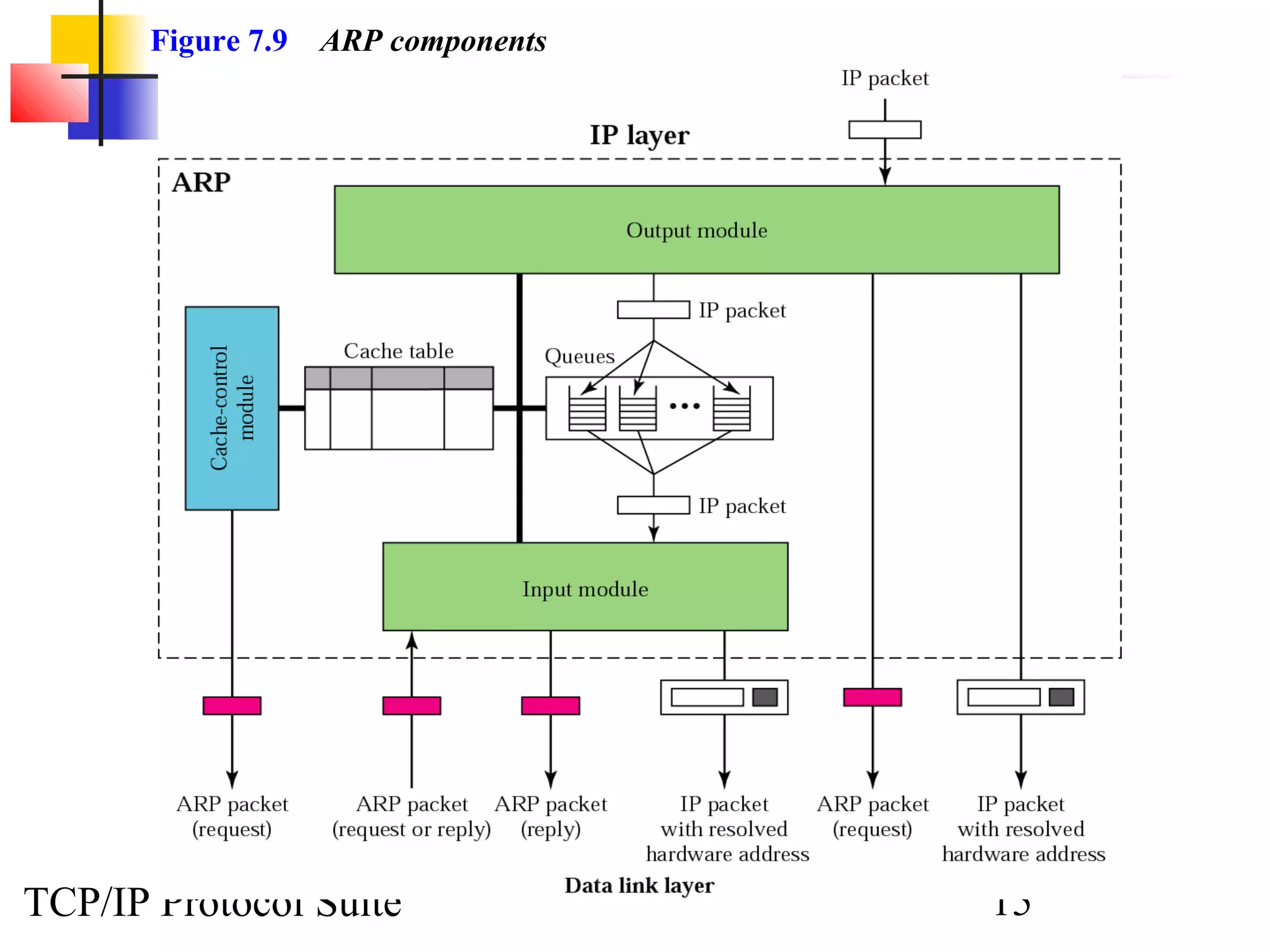
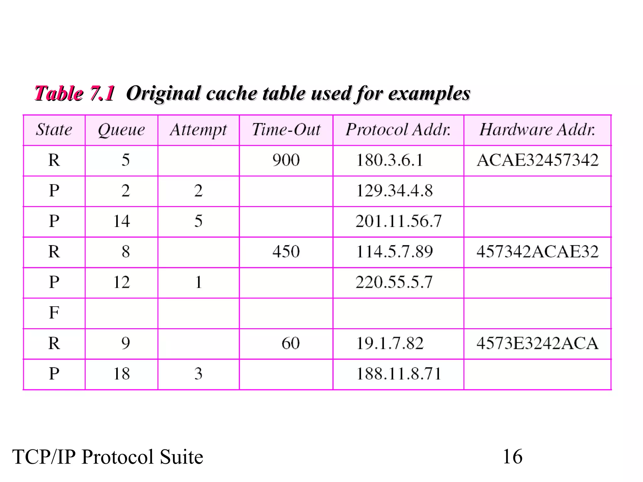
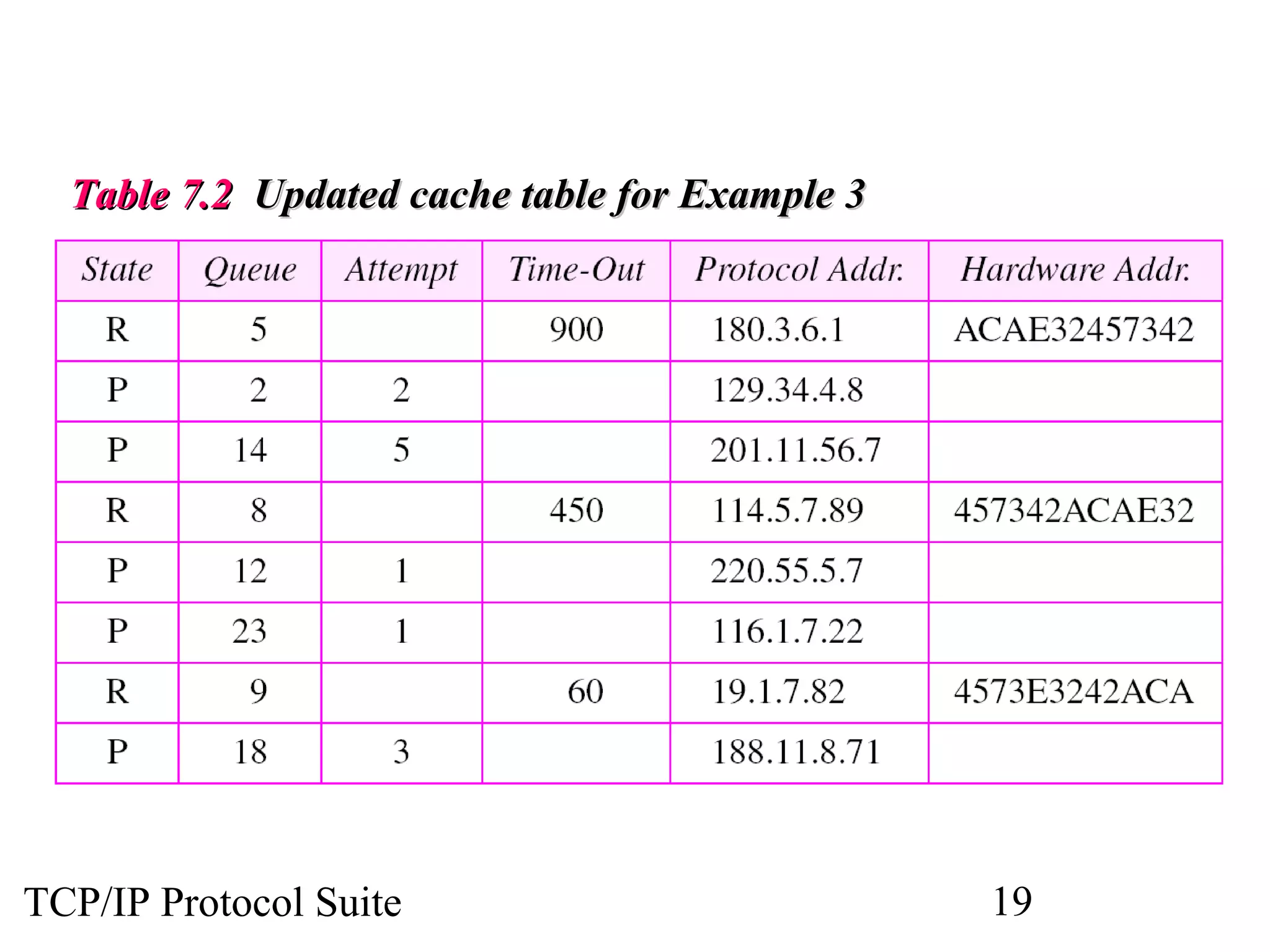
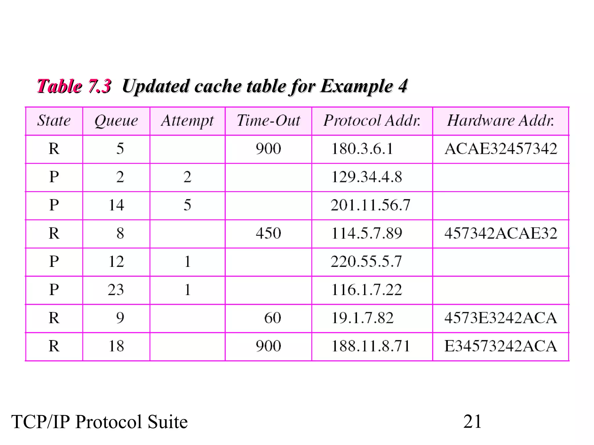
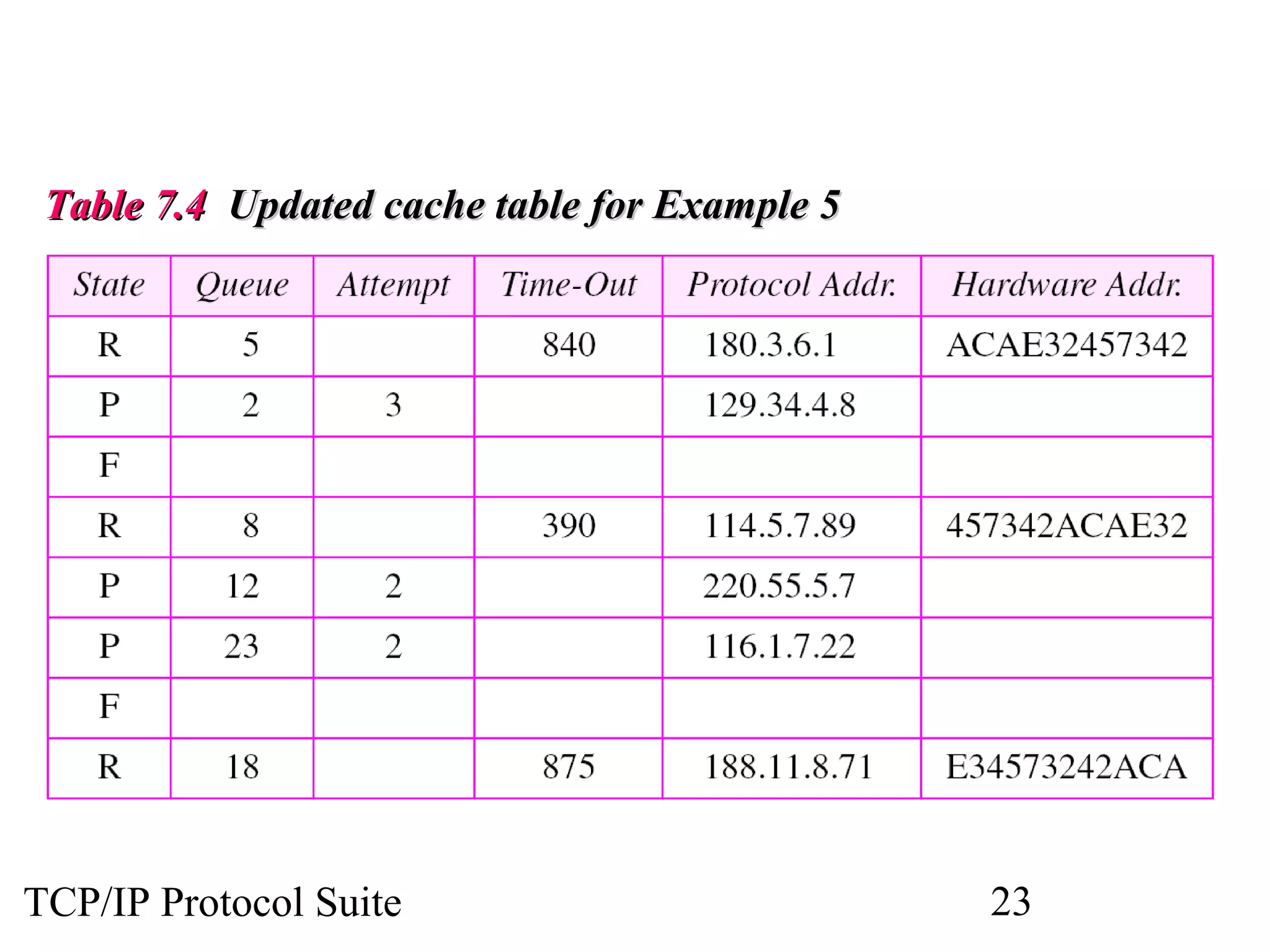
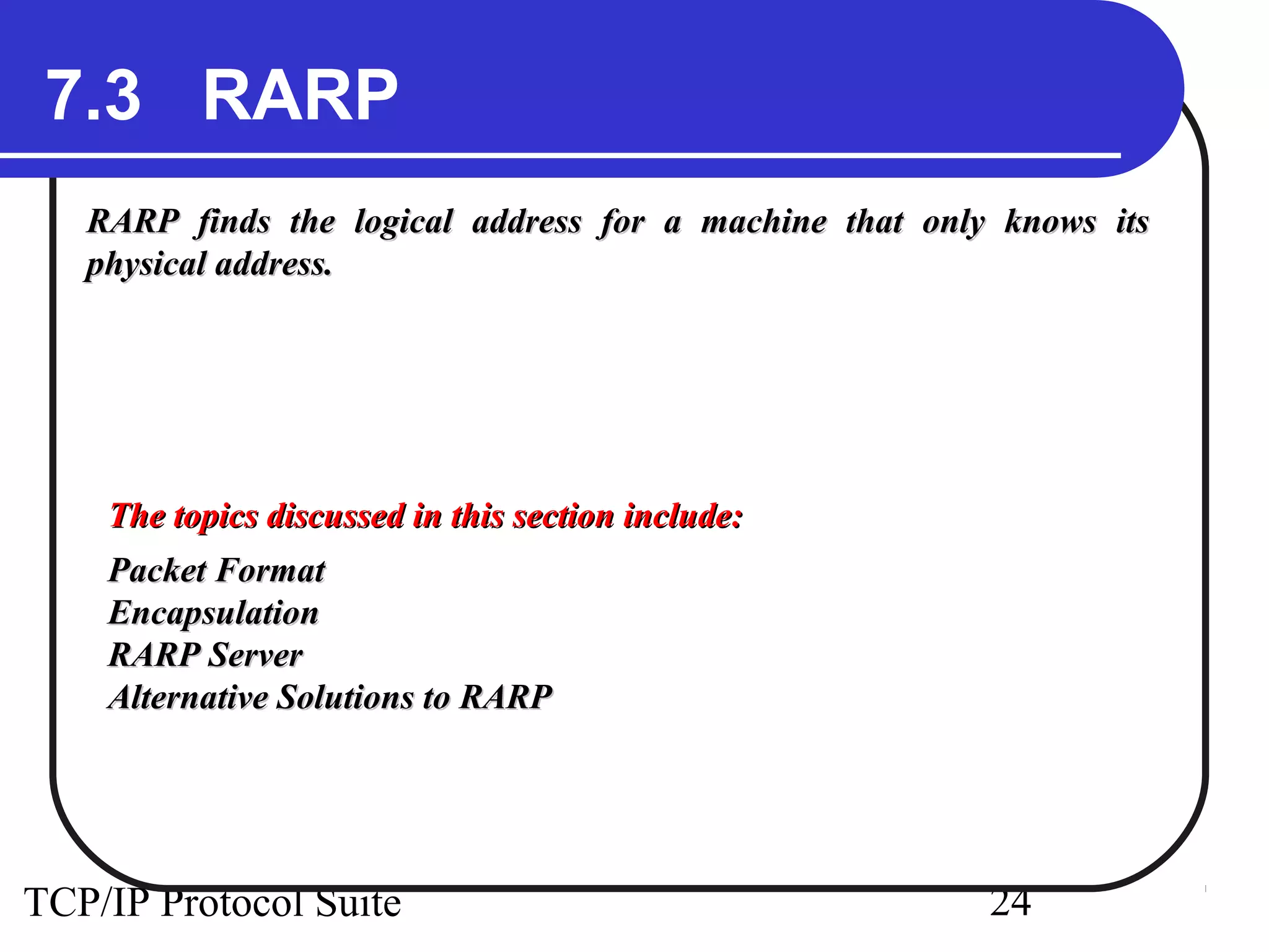
Chapter

7

ARP and RARP
Objectives
Upon completion you will be able to:
• Understand the need for ARP
• Understand the cases in which ARP is used
• Understand the components and interactions in an ARP package
• Understand the need for RARP

TCP/IP Protocol Suite

1
Figure 7.1

ARP and RARP

TCP/IP Protocol Suite

2
Figure 7.2

Position of ARP and RARP in TCP/IP protocol suite

TCP/IP Protocol Suite

3
7.1 ARP
ARP associates an IP address with its physical address. On a typical
physical network, such as a LAN, each device on a link is identified by a
physical or station address that is usually imprinted on the NIC.

The topics discussed in this section include:
Packet Format
Encapsulation
Operation
ARP over ATM
Proxy ARP

TCP/IP Protocol Suite

4
Figure 7.3

ARP operation

TCP/IP Protocol Suite

5
Figure 7.4

ARP packet

TCP/IP Protocol Suite

6
Figure 7.5

Encapsulation of ARP packet

TCP/IP Protocol Suite

7
Figure 7.6

Four cases using ARP

TCP/IP Protocol Suite

8
Note:
An ARP request is broadcast;
an ARP reply is unicast.

TCP/IP Protocol Suite

9
ExamplE 1

A host with IP address 130.23.43.20 and physical
address B2:34:55:10:22:10 has a packet to send to
another host with IP address 130.23.43.25 and
physical address A4:6E:F4:59:83:AB (which is
unknown to the first host). The two hosts are on the
same Ethernet network. Show the ARP request and
reply packets encapsulated in Ethernet frames.
See Next Slide
TCP/IP Protocol Suite

10
ExamplE 1

(ContinuEd)

Solution
Figure 7.7 shows the ARP request and reply packets.
Note that the ARP data field in this case is 28 bytes,
and that the individual addresses do not fit in the 4byte boundary. That is why we do not show the
regular 4-byte boundaries for these addresses. Also
note that the IP addresses are shown in hexadecimal.
For information on binary or hexadecimal notation
see Appendix B.
See Next Slide
TCP/IP Protocol Suite

11
Figure 7.7

Example 1

TCP/IP Protocol Suite

12
Figure 7.8

Proxy ARP

TCP/IP Protocol Suite

13
7.2 ARP PACKAGE
In this section, we give an example of a simplified ARP software
package to show the components and the relationships between the
components. This ARP package involves five modules: a cache table,
queues, an output module, an input module, and a cache-control
module.
The topics discussed in this section include:
Cache Table
Queues
Output Module
Input Module
Cache-Control Module

TCP/IP Protocol Suite

14
Figure 7.9

ARP components

TCP/IP Protocol Suite

15
Table 7.1 Original cache table used for examples

TCP/IP Protocol Suite

16
ExamplE 2

The ARP output module receives an IP datagram
(from the IP layer) with the destination address
114.5.7.89. It checks the cache table and finds that an
entry exists for this destination with the RESOLVED
state (R in the table). It extracts the hardware address,
which is 457342ACAE32, and sends the packet and
the address to the data link layer for transmission.
The cache table remains the same.

TCP/IP Protocol Suite

17
ExamplE 3

Twenty seconds later, the ARP output module receives
an IP datagram (from the IP layer) with the
destination address 116.1.7.22. It checks the cache
table and does not find this destination in the table.
The module adds an entry to the table with the state
PENDING and the Attempt value 1. It creates a new
queue for this destination and enqueues the packet. It
then sends an ARP request to the data link layer for
this destination. The new cache table is shown in
Table 7.2.
See Next Slide
TCP/IP Protocol Suite

18
Table 7.2 Updated cache table for Example 3

TCP/IP Protocol Suite

19
ExamplE 4

Fifteen seconds later, the ARP input module receives
an ARP packet with target protocol (IP) address
188.11.8.71. The module checks the table and finds
this address. It changes the state of the entry to
RESOLVED and sets the time-out value to 900. The
module then adds the target hardware address
(E34573242ACA) to the entry. Now it accesses queue
18 and sends all the packets in this queue, one by one,
to the data link layer. The new cache table is shown in
Table 7.3.
See Next Slide
TCP/IP Protocol Suite

20
Table 7.3 Updated cache table for Example 4

TCP/IP Protocol Suite

21
ExamplE 5

Twenty-five seconds later, the cache-control module
updates every entry. The time-out values for the first
three resolved entries are decremented by 60. The
time-out value for the last resolved entry is
decremented by 25. The state of the next-to-the last
entry is changed to FREE because the time-out is
zero. For each of the three pending entries, the value
of the attempts
See Next Slide
TCP/IP Protocol Suite

22
Table 7.4 Updated cache table for Example 5

TCP/IP Protocol Suite

23
7.3 RARP
RARP finds the logical address for a machine that only knows its
physical address.

The topics discussed in this section include:
Packet Format
Encapsulation
RARP Server
Alternative Solutions to RARP

TCP/IP Protocol Suite

24
Note:
The RARP request packets are broadcast;
the RARP reply packets are unicast.

TCP/IP Protocol Suite

25
Figure 7.10

RARP operation

TCP/IP Protocol Suite

26
Figure 7.11

RARP packet

TCP/IP Protocol Suite

27
Figure 7.12

Encapsulation of RARP packet

TCP/IP Protocol Suite

28

Arp

  • 1.
    Chapter 7 ARP and RARP Objectives Uponcompletion you will be able to: • Understand the need for ARP • Understand the cases in which ARP is used • Understand the components and interactions in an ARP package • Understand the need for RARP TCP/IP Protocol Suite 1
  • 2.
    Figure 7.1 ARP andRARP TCP/IP Protocol Suite 2
  • 3.
    Figure 7.2 Position ofARP and RARP in TCP/IP protocol suite TCP/IP Protocol Suite 3
  • 4.
    7.1 ARP ARP associatesan IP address with its physical address. On a typical physical network, such as a LAN, each device on a link is identified by a physical or station address that is usually imprinted on the NIC. The topics discussed in this section include: Packet Format Encapsulation Operation ARP over ATM Proxy ARP TCP/IP Protocol Suite 4
  • 5.
  • 6.
  • 7.
    Figure 7.5 Encapsulation ofARP packet TCP/IP Protocol Suite 7
  • 8.
    Figure 7.6 Four casesusing ARP TCP/IP Protocol Suite 8
  • 9.
    Note: An ARP requestis broadcast; an ARP reply is unicast. TCP/IP Protocol Suite 9
  • 10.
    ExamplE 1 A hostwith IP address 130.23.43.20 and physical address B2:34:55:10:22:10 has a packet to send to another host with IP address 130.23.43.25 and physical address A4:6E:F4:59:83:AB (which is unknown to the first host). The two hosts are on the same Ethernet network. Show the ARP request and reply packets encapsulated in Ethernet frames. See Next Slide TCP/IP Protocol Suite 10
  • 11.
    ExamplE 1 (ContinuEd) Solution Figure 7.7shows the ARP request and reply packets. Note that the ARP data field in this case is 28 bytes, and that the individual addresses do not fit in the 4byte boundary. That is why we do not show the regular 4-byte boundaries for these addresses. Also note that the IP addresses are shown in hexadecimal. For information on binary or hexadecimal notation see Appendix B. See Next Slide TCP/IP Protocol Suite 11
  • 12.
    Figure 7.7 Example 1 TCP/IPProtocol Suite 12
  • 13.
    Figure 7.8 Proxy ARP TCP/IPProtocol Suite 13
  • 14.
    7.2 ARP PACKAGE Inthis section, we give an example of a simplified ARP software package to show the components and the relationships between the components. This ARP package involves five modules: a cache table, queues, an output module, an input module, and a cache-control module. The topics discussed in this section include: Cache Table Queues Output Module Input Module Cache-Control Module TCP/IP Protocol Suite 14
  • 15.
  • 16.
    Table 7.1 Originalcache table used for examples TCP/IP Protocol Suite 16
  • 17.
    ExamplE 2 The ARPoutput module receives an IP datagram (from the IP layer) with the destination address 114.5.7.89. It checks the cache table and finds that an entry exists for this destination with the RESOLVED state (R in the table). It extracts the hardware address, which is 457342ACAE32, and sends the packet and the address to the data link layer for transmission. The cache table remains the same. TCP/IP Protocol Suite 17
  • 18.
    ExamplE 3 Twenty secondslater, the ARP output module receives an IP datagram (from the IP layer) with the destination address 116.1.7.22. It checks the cache table and does not find this destination in the table. The module adds an entry to the table with the state PENDING and the Attempt value 1. It creates a new queue for this destination and enqueues the packet. It then sends an ARP request to the data link layer for this destination. The new cache table is shown in Table 7.2. See Next Slide TCP/IP Protocol Suite 18
  • 19.
    Table 7.2 Updatedcache table for Example 3 TCP/IP Protocol Suite 19
  • 20.
    ExamplE 4 Fifteen secondslater, the ARP input module receives an ARP packet with target protocol (IP) address 188.11.8.71. The module checks the table and finds this address. It changes the state of the entry to RESOLVED and sets the time-out value to 900. The module then adds the target hardware address (E34573242ACA) to the entry. Now it accesses queue 18 and sends all the packets in this queue, one by one, to the data link layer. The new cache table is shown in Table 7.3. See Next Slide TCP/IP Protocol Suite 20
  • 21.
    Table 7.3 Updatedcache table for Example 4 TCP/IP Protocol Suite 21
  • 22.
    ExamplE 5 Twenty-five secondslater, the cache-control module updates every entry. The time-out values for the first three resolved entries are decremented by 60. The time-out value for the last resolved entry is decremented by 25. The state of the next-to-the last entry is changed to FREE because the time-out is zero. For each of the three pending entries, the value of the attempts See Next Slide TCP/IP Protocol Suite 22
  • 23.
    Table 7.4 Updatedcache table for Example 5 TCP/IP Protocol Suite 23
  • 24.
    7.3 RARP RARP findsthe logical address for a machine that only knows its physical address. The topics discussed in this section include: Packet Format Encapsulation RARP Server Alternative Solutions to RARP TCP/IP Protocol Suite 24
  • 25.
    Note: The RARP requestpackets are broadcast; the RARP reply packets are unicast. TCP/IP Protocol Suite 25
  • 26.
  • 27.
  • 28.
    Figure 7.12 Encapsulation ofRARP packet TCP/IP Protocol Suite 28