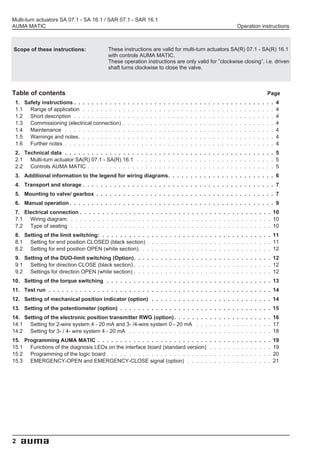
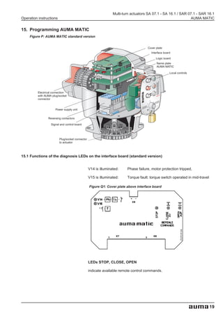
This document provides operation instructions for multi-turn actuators models SA 07.1 - SA 16.1 and SAR 07.1 - SAR 16.1 with AUMA MATIC controls. It describes the scope, technical specifications, safety instructions, transport and storage, mounting, manual operation, electrical connection, setting of limit switches, torque switching, position indicators, and maintenance procedures. The document contains 21 sections covering all aspects of installation, setup and maintenance of the actuators.


![Multi-turn actuators SA 07.1 - SA 16.1 / SAR 07.1 - SAR 16.1
Operation instructions AUMA MATIC
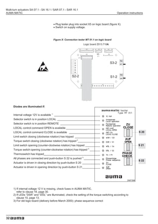
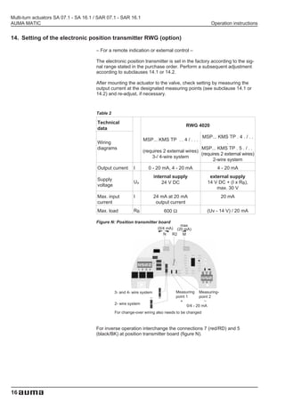
16.8 Positioner in Split Range version (option)
For Split Range a modified version of the positioner is used. The standard
version is not suitable for Split Range operation.
16.8.1 Split Range: description of functions
Split Range allows the adaptation of the positioner to nominal value ranges
which are for example necessary to individually control several actuators
(up to 4 actuators) with the same nominal value signal. Typical values for 2
actuators are 0 - 10 mA and 10 - 20 mA or 4 - 12 mA and 12 - 20 mA. But
all other values between 0/4 - 20 mA can also be set and adjusted.
16.8.2 Programming
Programming of the positioner at the code switches S1-7, S2-7, S3-7 can,
with the exception indicated below, be performed in the same manner as for
normal operation.
Switch S1-7 DIP 5 at code switch S1-7 must always be in
position ON for Split Range version.
16.8.3 Positioner adjustment for Split Range
.(See also example on page 28)
Supply the specified minimum input signal (nominal value E1) for the
positioner and check by measuring with Voltmeter at the measuring points
.MP3 and MP4 (figure T).
Connect voltmeter to measuring points M3 and MP1.
Calculate setting value:
Initial value = E 1min [in Ampere] x 250 Ohm
.Set initial value with potentiometer P5.
Supply specified maximum command signal (nominal value E1) and
.check by measuring at the measuring points MP3 and MP4.
Connect voltmeter between measuring point M9 and measuring point
.MP1. Set 5 V with potentiometer P6 .
Supply input signal E1 from minimum to maximum value and check the
set range 0 - 5 V at measuring point M9. If necessary, readjust with P5 or
.P6.
Apply the same procedure to the second actuator’s positioner and set
.according to the specified nominal value E1.
After setting for Split Range operation, perform further readjustment as
described in subclause 16.3, page 23.
Figure T: Positioner board A7, Split Range version
P9 (DE)
P7 (Sens)
P3 (0)
S2-7
P4 (max)
P6 S3-7
P5
Measuring
points
V28 (green)
OFF
ON
V27 (yellow)
V18 (red)
MP4(–) V10 (red)
Meas. E1 MP3(+) P10
points MP2(+)
E2 MP1(–) P8
ON
OFF
S1-7
27](https://image.slidesharecdn.com/auma-100309221701-phpapp01/85/Auma-27-320.jpg)