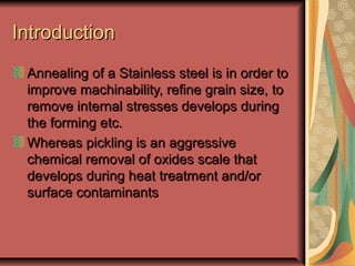
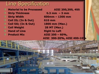
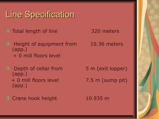
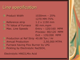
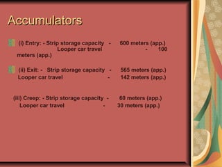
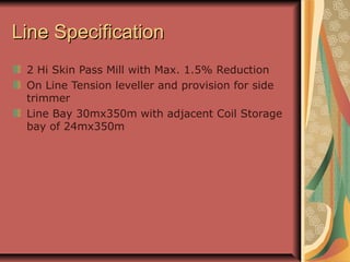
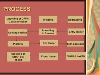
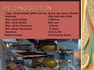
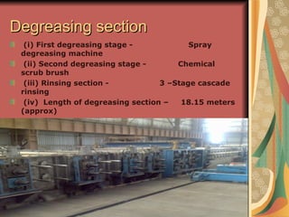
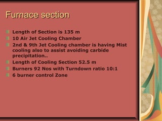
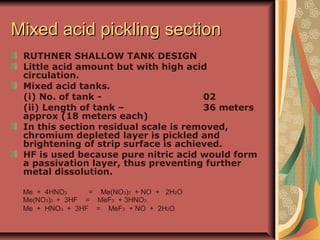
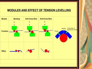
IntroductionIntroduction
Annealing of a Stainless steel is in order toAnnealing of a Stainless steel is in order to
improve machinability, refine grain size, toimprove machinability, refine grain size, to
remove internal stresses develops duringremove internal stresses develops during
the forming etc.the forming etc.
Whereas pickling is an aggressiveWhereas pickling is an aggressive
chemical removal of oxides scale thatchemical removal of oxides scale that
develops during heat treatment and/ordevelops during heat treatment and/or
surface contaminantssurface contaminants
Line SpecificationLine Specification
Material to be Processed AISI 200,300, 400Material to be Processed AISI 200,300, 400
Strip ThicknessStrip Thickness 0.3 mm – 3 mm0.3 mm – 3 mm
Strip WidthStrip Width 600mm – 1300 mm600mm – 1300 mm
Coil ID; (In & Out)Coil ID; (In & Out) 610 mm610 mm
Coil OD; (In & Out)Coil OD; (In & Out) 1800 mm (Max.)1800 mm (Max.)
Coil WeightCoil Weight 28 MT (Max.)28 MT (Max.)
Hand of LineHand of Line Right to LeftRight to Left
Product MixProduct Mix AISI 200 – 60%,AISI 200 – 60%,
AISI 300-30%, AISI 400-10%AISI 300-30%, AISI 400-10%
Line SpecificationLine Specification
Total length of line 320 meters
Height of equipment from 10.36 meters
(app.)
+ 0 mill floors level
Depth of cellar from 5 m (exit lopper)
(app.)
+ 0 mill floors level 7.5 m (sump pit)
(app.)
Crane hook height 10.935 m
Line specificationLine specification
Product Width 1030mm – 25%
1270 MM-75%
Reference strip 1.2 x 1150 mm
TV Value of Furnace 80 mm.mpm
Max. Line Speeds Entry – 120/160 MPM
Process– 80/120 MPM
Exit – 135/200 MPM
Production at Ref Strip 40.88 Ton / Hr
Annual Production 2,50,000 MTPA
Furnace having Flox Burner by LPG
Pickling by Electrolytic Na2SO4,
Electrolytic HNO3,Mix Acid
AccumulatorsAccumulators
(i) Entry: - Strip storage capacity - 600 meters (app.)
Looper car travel - 100
meters (app.)
(ii) Exit: - Strip storage capacity - 565 meters (app.)
Looper car travel - 142 meters (app.)
(iii) Creep: - Strip storage capacity - 60 meters (app.)
Looper car travel - 30 meters (app.)
Line SpecificationLine Specification
2 Hi Skin Pass Mill with Max. 1.5% Reduction
On Line Tension leveller and provision for side
trimmer
Line Bay 30mx350m with adjacent Coil Storage
bay of 24mx350m
Line Consists OfLine Consists Of
Entry Equipments with Looper
Welding machine from Guild,USA
Degreasing Unit
Annealing furnace
Pickling section
Skin pass mill with Creep looper
On-line Tension leveller and provision for side trimmer.
Exit equipments with looper
All Auxiliaries which includes Acid Storage, ETP, WT,
DM water plant Etc.
PROCESSPROCESS
Uncoiling of CRFH
Coil at uncoiler
Welding Degreasing
Entry looper
Annealing
in furnaceCooling section
Pickling Exit looper Skin pass mill
Tension levellerCreep looper
Recoiling of
CRAP coil
at exit
Entry EquipmentEntry Equipment
2 Uncoiler with CPC unit
Paper winder with tension feedback unit
Pinchrolls,5 roll flatteners,Up cut shears,belt conveyors
Flat leader end handling system by vacuum
stacker;Bottom side shiftable
Bridles;deflector,steering rolls;PU coated roll dia 1000
mmx1600 mm
Automatic seam welding machine from Guild USA;
Welding time #4 min..
Coil car, coil centering system
WELDING SECTIONWELDING SECTION
Type -Guild Model QMM 125-54, Quick lap Seam Welder
Material 200,300,400 CRSS
Max. Strip Width 1300mm
Min. Strip Width 600 mm
Max. Strip Thickness 3.0mm
Min. Strip Thickness 0.3mm
Electrics 415/3/50
Weld Process Continuous Seam
Degreasing sectionDegreasing section
(i) First degreasing stage - Spray
degreasing machine
(ii) Second degreasing stage - Chemical
scrub brush
(iii) Rinsing section - 3 –Stage cascade
rinsing
(iv) Length of degreasing section – 18.15 meters
(approx)
ANNEALINGANNEALING
Annealing is done to:
1. To regain grain structure
2. To increase malleability and ductility.
3. To attain mechanical properties.
ANNEALING STAGES
1. Recovery
2. Recrystallization
3. Grain growth
Furnace sectionFurnace section
Length of Section is 135 m
10 Air Jet Cooling Chamber
2nd & 9th Jet Cooling chamber is having Mist
cooling also to assist avoiding carbide
precipitation..
Length of Cooling Section 52.5 m
Burners 92 Nos with Turndown ratio 10:1
6 burner control Zone
Furnace sectionFurnace section
3 Radiation Pyrometer at Exit of each Chamber.
4 Optical Pyrometer at Jet Cooling Section
Radar Type Furnace sensor.
Burner Flame sensor, Ionization Type
Furnace Pressure Sensor.
Fuel Consumption 22 kg/Ton.
Temperature of Strip AISI 200 – 950 C
AISI 300 – 1020-1140 C
AISI 400 – 740-870 C
Recuperator; Air out temp will be ~ 600 C.
Air Curtains at Exit of Furnace
Threading System
Roll removal Rig
Retraction Cooling Section.
Furnace sectionFurnace section
a) TV valve (m/min, mm) for 304 annealing 80
b) TV valve (m/min, mm) for 430 annealing 60
c) Max furnace operating temp 1250ºc
d) Setting range of air/gas ratio 1.1 – 1.6
(i) Total length of the furnace 73,900 m
(ii) Total length of the cooling section 52,500 m
(iii) Length of unfired preheating section 21,000 m
(iv) Height of strip pass line above support floor 2500mm
(v) Furnace chamber 04 chambers
1st chamber: - unfired preheating section
2nd chamber: - unfired + 1st fired zone
3rd chamber: - 02 fired zones
4th chamber: - 03 fired zones
(vi) No. of burner's – 92 (26/36/30)
Burner input / chamber – 22.6 MW (7.6 / 9.2 / 6.1MW)
Stable combustion without a flame andStable combustion without a flame and
defined recirculation of hot combustiondefined recirculation of hot combustion
productsproducts
Flox burners
Flox and flame temperature fieldFlox and flame temperature field
PICKLINGPICKLING
The function of pickling is to dissolve/
remove/ peel off oxide layer on surface of
strip. Such oxide layers are formed during
hot rolling and in case of cold rolled strip
during annealing operation.
IN AP-4 PICKLING IS DONE IN 3 SECTIONS
 Neolyte electrolytic pickling section
 Nitric electrolytic pickling section
 Mixed acid pickling section
Neolyte electrolytic pickling sectionNeolyte electrolytic pickling section
Aqueous solution of sodium sulphate is used.
Strip is descaled with help of electric current.
(i) No. of tank - 01
(ii) Length of tank – 50 metes (approx)
(iii) Rectifier - 8 sets(2 x 5500A)
(iv) Electrode - No of sets – 24
(8 anode sets, 16, cathode
sets)
8 Cells with combination of Cathode-Anode-
Cathode.
Tank made of MS lined with Brick & Rubber
Tank covers made of PP
2 Pair of Squeeze roll at Entry & Exit
Support roll arranged such as the strip moves in
Neolyte electrolytic pickling sectionNeolyte electrolytic pickling section
Chemical reactions
Equilibrium reactions
H2O = OH- + H+
Na2SO4 = 2Na+ + SO4-
Anode process
2OH- = H2O + 1/2O2 + 2e-
2H+ + SO4- = H2SO4
Fe2O3 = 2Fe++ + 3/2O2 + 6e-
Fe = Fe+++ + 3e-
Cr2O3 + 5H2O = 2CrO4- + 10H+ + 6e-
Cr + 4H2O = CrO4- + 8H+ + 6e-
Cathode Process
2H+ + 2e- = H2
2OH- + 2Na = 2NaOH
Nitric electrolytic pickling sectionNitric electrolytic pickling section
HORIZONTAL RUTHNER ZIG ZAG DESIGN
(i) No. of tank - 01
(ii) Length of tank – 14 meters (approx)
(iii) Rectifier - 01 sets (2 x 5500A)
(iv) Electrode - No of sets - 06
(02 anode sets, 04 cathode
sets)
Pickling is effected in nitric acid by alternate anodic and
cathodic polarization of strip.
Low current density is used to just remove the passivation
layer from the strip so that the chemical reaction between
HNO3 and strip surface is enabled.
Disadvantage of the NITRIC acid being electrolyte is that
a higher current density NOx is produced.
DeNOx system is used for NOx emissions.
Mixed acid pickling sectionMixed acid pickling section
RUTHNER SHALLOW TANK DESIGN
Little acid amount but with high acid
circulation.
Mixed acid tanks.
(i) No. of tank - 02
(ii) Length of tank – 36 meters
approx (18 meters each)
In this section residual scale is removed,
chromium depleted layer is pickled and
brightening of strip surface is achieved.
HF is used because pure nitric acid would form
a passivation layer, thus preventing further
metal dissolution.
Me + 4HNO3 = Me(NO3)2 + NO + 2H2O
Me(NO3)3 + 3HF = MeF3 + 3HNO3
Me + HNO3 + 3HF = MeF3 + NO + 2H2O
COIL AFTER PICKLINGCOIL AFTER PICKLING
Skin Pass MillSkin Pass Mill
Skin passing is done to
1. To improve strip shape
2. To impart the desired surface finish to steel from
2D to 2B
3. To produce desired mechanical properties.
4. To eliminate minor surface blemishes.
5. Masking of yield point
2 Hi Mill
Elongation 1.5%
Roll Cleaning system
Bottom Roll having Hydraulic Gap Control
Quick Roll Changing device;
Roll changing time ~ 8 minutes
Roll changing is possible during running
High Pressure Hydraulic system
2 High roll – 800mm (max.) /
750mm (min.) x 1500mm barrel length.
Roll force – Max. 10,000 KN
Tension LevellerTension Leveller
The purpose of tension levelling is to bring all the fibres
in the metal to equal length
To achieve Desired strip elongation(0-2%) and strip flatness
Tension leveller consists of Entry bridle, Tension leveller wet
type process, Exit bridles
Type – wet type.
Design – One set of bending roll cartridge
Two sets of anti cross bow roll cartridge
Tension – 350 KN (max.)
Roll configuration.
Bending roll module: 6 – High
Anti cross bow roll module: 3 – High
Roll sizes.
Bending: - work roll – 35mmØ x 1600mm
Intermediate roll - 50mmØ x 1600mm
Back up roll - 60mmØ x 130mm
Anti cross: - work roll – 150mmØ x 1600mm
Back up roll - 60mmØ x 130mm
Tension
Bending Combination of
Bending and Tension
Anti-Cross BowBending
Effect
Function
MODULES AND EFFECT OF TENSION LEVELLING
Module Anti-Cross Bow
Hydraulic cylinder
with integrated linear
transducer
Monoblo
c Frame
Passlin
e roll
Dry air
nozzle pipe
Bending
cartridge with
support rolls
protected by
purging air
Anti Cross
Bow
cartridge
with support
rolls
Adjustable
upper
cartridge
Cartridge clamping
cylinders
Servo valves
Fully enclosed Scale Breaker frame
Adjustable in
and outlet
Scale removal motor with
auger conveyor (Option)
LEVELLER IN MONOBLOC DESIGNLEVELLER IN MONOBLOC DESIGN
Exit EquipmentsExit Equipments
1 Recoiler with EPC Unit
Paper unwinder with Tension feedback unit
Pinch Rolls, Up Cut Shears, Belt Conveyor.
Bridles, Deflector, Steering rolls; PU coated
Roll dia 1000 mm x 1600mm.
Coil car with a provision to travel in other bay
4 Strands Dolly Type Looper; Storage capacity
566 m.
On line Weighing, Manual Strapping
Hydraulics & Pneumatic Systems
Ap 4 presentation

Ap 4 presentation

  • 2.
    IntroductionIntroduction Annealing of aStainless steel is in order toAnnealing of a Stainless steel is in order to improve machinability, refine grain size, toimprove machinability, refine grain size, to remove internal stresses develops duringremove internal stresses develops during the forming etc.the forming etc. Whereas pickling is an aggressiveWhereas pickling is an aggressive chemical removal of oxides scale thatchemical removal of oxides scale that develops during heat treatment and/ordevelops during heat treatment and/or surface contaminantssurface contaminants
  • 3.
    Line SpecificationLine Specification Materialto be Processed AISI 200,300, 400Material to be Processed AISI 200,300, 400 Strip ThicknessStrip Thickness 0.3 mm – 3 mm0.3 mm – 3 mm Strip WidthStrip Width 600mm – 1300 mm600mm – 1300 mm Coil ID; (In & Out)Coil ID; (In & Out) 610 mm610 mm Coil OD; (In & Out)Coil OD; (In & Out) 1800 mm (Max.)1800 mm (Max.) Coil WeightCoil Weight 28 MT (Max.)28 MT (Max.) Hand of LineHand of Line Right to LeftRight to Left Product MixProduct Mix AISI 200 – 60%,AISI 200 – 60%, AISI 300-30%, AISI 400-10%AISI 300-30%, AISI 400-10%
  • 4.
    Line SpecificationLine Specification Totallength of line 320 meters Height of equipment from 10.36 meters (app.) + 0 mill floors level Depth of cellar from 5 m (exit lopper) (app.) + 0 mill floors level 7.5 m (sump pit) (app.) Crane hook height 10.935 m
  • 5.
    Line specificationLine specification ProductWidth 1030mm – 25% 1270 MM-75% Reference strip 1.2 x 1150 mm TV Value of Furnace 80 mm.mpm Max. Line Speeds Entry – 120/160 MPM Process– 80/120 MPM Exit – 135/200 MPM Production at Ref Strip 40.88 Ton / Hr Annual Production 2,50,000 MTPA Furnace having Flox Burner by LPG Pickling by Electrolytic Na2SO4, Electrolytic HNO3,Mix Acid
  • 6.
    AccumulatorsAccumulators (i) Entry: -Strip storage capacity - 600 meters (app.) Looper car travel - 100 meters (app.) (ii) Exit: - Strip storage capacity - 565 meters (app.) Looper car travel - 142 meters (app.) (iii) Creep: - Strip storage capacity - 60 meters (app.) Looper car travel - 30 meters (app.)
  • 7.
    Line SpecificationLine Specification 2Hi Skin Pass Mill with Max. 1.5% Reduction On Line Tension leveller and provision for side trimmer Line Bay 30mx350m with adjacent Coil Storage bay of 24mx350m
  • 8.
    Line Consists OfLineConsists Of Entry Equipments with Looper Welding machine from Guild,USA Degreasing Unit Annealing furnace Pickling section Skin pass mill with Creep looper On-line Tension leveller and provision for side trimmer. Exit equipments with looper All Auxiliaries which includes Acid Storage, ETP, WT, DM water plant Etc.
  • 9.
    PROCESSPROCESS Uncoiling of CRFH Coilat uncoiler Welding Degreasing Entry looper Annealing in furnaceCooling section Pickling Exit looper Skin pass mill Tension levellerCreep looper Recoiling of CRAP coil at exit
  • 11.
    Entry EquipmentEntry Equipment 2Uncoiler with CPC unit Paper winder with tension feedback unit Pinchrolls,5 roll flatteners,Up cut shears,belt conveyors Flat leader end handling system by vacuum stacker;Bottom side shiftable Bridles;deflector,steering rolls;PU coated roll dia 1000 mmx1600 mm Automatic seam welding machine from Guild USA; Welding time #4 min.. Coil car, coil centering system
  • 12.
    WELDING SECTIONWELDING SECTION Type-Guild Model QMM 125-54, Quick lap Seam Welder Material 200,300,400 CRSS Max. Strip Width 1300mm Min. Strip Width 600 mm Max. Strip Thickness 3.0mm Min. Strip Thickness 0.3mm Electrics 415/3/50 Weld Process Continuous Seam
  • 13.
    Degreasing sectionDegreasing section (i)First degreasing stage - Spray degreasing machine (ii) Second degreasing stage - Chemical scrub brush (iii) Rinsing section - 3 –Stage cascade rinsing (iv) Length of degreasing section – 18.15 meters (approx)
  • 14.
    ANNEALINGANNEALING Annealing is doneto: 1. To regain grain structure 2. To increase malleability and ductility. 3. To attain mechanical properties. ANNEALING STAGES 1. Recovery 2. Recrystallization 3. Grain growth
  • 15.
    Furnace sectionFurnace section Lengthof Section is 135 m 10 Air Jet Cooling Chamber 2nd & 9th Jet Cooling chamber is having Mist cooling also to assist avoiding carbide precipitation.. Length of Cooling Section 52.5 m Burners 92 Nos with Turndown ratio 10:1 6 burner control Zone
  • 16.
    Furnace sectionFurnace section 3Radiation Pyrometer at Exit of each Chamber. 4 Optical Pyrometer at Jet Cooling Section Radar Type Furnace sensor. Burner Flame sensor, Ionization Type Furnace Pressure Sensor. Fuel Consumption 22 kg/Ton. Temperature of Strip AISI 200 – 950 C AISI 300 – 1020-1140 C AISI 400 – 740-870 C Recuperator; Air out temp will be ~ 600 C. Air Curtains at Exit of Furnace Threading System Roll removal Rig Retraction Cooling Section.
  • 17.
    Furnace sectionFurnace section a)TV valve (m/min, mm) for 304 annealing 80 b) TV valve (m/min, mm) for 430 annealing 60 c) Max furnace operating temp 1250ºc d) Setting range of air/gas ratio 1.1 – 1.6 (i) Total length of the furnace 73,900 m (ii) Total length of the cooling section 52,500 m (iii) Length of unfired preheating section 21,000 m (iv) Height of strip pass line above support floor 2500mm (v) Furnace chamber 04 chambers 1st chamber: - unfired preheating section 2nd chamber: - unfired + 1st fired zone 3rd chamber: - 02 fired zones 4th chamber: - 03 fired zones (vi) No. of burner's – 92 (26/36/30) Burner input / chamber – 22.6 MW (7.6 / 9.2 / 6.1MW)
  • 18.
    Stable combustion withouta flame andStable combustion without a flame and defined recirculation of hot combustiondefined recirculation of hot combustion productsproducts Flox burners
  • 19.
    Flox and flametemperature fieldFlox and flame temperature field
  • 20.
    PICKLINGPICKLING The function ofpickling is to dissolve/ remove/ peel off oxide layer on surface of strip. Such oxide layers are formed during hot rolling and in case of cold rolled strip during annealing operation. IN AP-4 PICKLING IS DONE IN 3 SECTIONS  Neolyte electrolytic pickling section  Nitric electrolytic pickling section  Mixed acid pickling section
  • 21.
    Neolyte electrolytic picklingsectionNeolyte electrolytic pickling section Aqueous solution of sodium sulphate is used. Strip is descaled with help of electric current. (i) No. of tank - 01 (ii) Length of tank – 50 metes (approx) (iii) Rectifier - 8 sets(2 x 5500A) (iv) Electrode - No of sets – 24 (8 anode sets, 16, cathode sets) 8 Cells with combination of Cathode-Anode- Cathode. Tank made of MS lined with Brick & Rubber Tank covers made of PP 2 Pair of Squeeze roll at Entry & Exit Support roll arranged such as the strip moves in
  • 22.
    Neolyte electrolytic picklingsectionNeolyte electrolytic pickling section Chemical reactions Equilibrium reactions H2O = OH- + H+ Na2SO4 = 2Na+ + SO4- Anode process 2OH- = H2O + 1/2O2 + 2e- 2H+ + SO4- = H2SO4 Fe2O3 = 2Fe++ + 3/2O2 + 6e- Fe = Fe+++ + 3e- Cr2O3 + 5H2O = 2CrO4- + 10H+ + 6e- Cr + 4H2O = CrO4- + 8H+ + 6e- Cathode Process 2H+ + 2e- = H2 2OH- + 2Na = 2NaOH
  • 23.
    Nitric electrolytic picklingsectionNitric electrolytic pickling section HORIZONTAL RUTHNER ZIG ZAG DESIGN (i) No. of tank - 01 (ii) Length of tank – 14 meters (approx) (iii) Rectifier - 01 sets (2 x 5500A) (iv) Electrode - No of sets - 06 (02 anode sets, 04 cathode sets) Pickling is effected in nitric acid by alternate anodic and cathodic polarization of strip. Low current density is used to just remove the passivation layer from the strip so that the chemical reaction between HNO3 and strip surface is enabled. Disadvantage of the NITRIC acid being electrolyte is that a higher current density NOx is produced. DeNOx system is used for NOx emissions.
  • 24.
    Mixed acid picklingsectionMixed acid pickling section RUTHNER SHALLOW TANK DESIGN Little acid amount but with high acid circulation. Mixed acid tanks. (i) No. of tank - 02 (ii) Length of tank – 36 meters approx (18 meters each) In this section residual scale is removed, chromium depleted layer is pickled and brightening of strip surface is achieved. HF is used because pure nitric acid would form a passivation layer, thus preventing further metal dissolution. Me + 4HNO3 = Me(NO3)2 + NO + 2H2O Me(NO3)3 + 3HF = MeF3 + 3HNO3 Me + HNO3 + 3HF = MeF3 + NO + 2H2O
  • 25.
  • 26.
    Skin Pass MillSkinPass Mill Skin passing is done to 1. To improve strip shape 2. To impart the desired surface finish to steel from 2D to 2B 3. To produce desired mechanical properties. 4. To eliminate minor surface blemishes. 5. Masking of yield point 2 Hi Mill Elongation 1.5% Roll Cleaning system Bottom Roll having Hydraulic Gap Control Quick Roll Changing device; Roll changing time ~ 8 minutes Roll changing is possible during running High Pressure Hydraulic system 2 High roll – 800mm (max.) / 750mm (min.) x 1500mm barrel length. Roll force – Max. 10,000 KN
  • 27.
    Tension LevellerTension Leveller Thepurpose of tension levelling is to bring all the fibres in the metal to equal length To achieve Desired strip elongation(0-2%) and strip flatness Tension leveller consists of Entry bridle, Tension leveller wet type process, Exit bridles Type – wet type. Design – One set of bending roll cartridge Two sets of anti cross bow roll cartridge Tension – 350 KN (max.) Roll configuration. Bending roll module: 6 – High Anti cross bow roll module: 3 – High Roll sizes. Bending: - work roll – 35mmØ x 1600mm Intermediate roll - 50mmØ x 1600mm Back up roll - 60mmØ x 130mm Anti cross: - work roll – 150mmØ x 1600mm Back up roll - 60mmØ x 130mm
  • 28.
    Tension Bending Combination of Bendingand Tension Anti-Cross BowBending Effect Function MODULES AND EFFECT OF TENSION LEVELLING Module Anti-Cross Bow
  • 29.
    Hydraulic cylinder with integratedlinear transducer Monoblo c Frame Passlin e roll Dry air nozzle pipe Bending cartridge with support rolls protected by purging air Anti Cross Bow cartridge with support rolls Adjustable upper cartridge Cartridge clamping cylinders Servo valves Fully enclosed Scale Breaker frame Adjustable in and outlet Scale removal motor with auger conveyor (Option) LEVELLER IN MONOBLOC DESIGNLEVELLER IN MONOBLOC DESIGN
  • 30.
    Exit EquipmentsExit Equipments 1Recoiler with EPC Unit Paper unwinder with Tension feedback unit Pinch Rolls, Up Cut Shears, Belt Conveyor. Bridles, Deflector, Steering rolls; PU coated Roll dia 1000 mm x 1600mm. Coil car with a provision to travel in other bay 4 Strands Dolly Type Looper; Storage capacity 566 m. On line Weighing, Manual Strapping Hydraulics & Pneumatic Systems