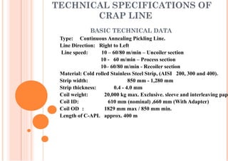
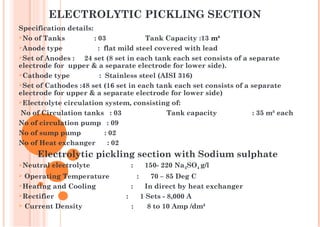
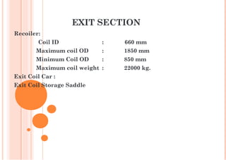
CRAP LINE
Presented By…..
Chandan kr. Singh
KEY SECTIONS OF LINE
TECHNICAL SPECIFICATIONS OF
CRAP LINE
BASIC TECHNICAL DATA
Type: Continuous Annealing Pickling Line.
Line Direction: Right to Left
Line speed: 10 – 60/80 m/min – Uncoiler section
10 - 60 m/min – Process section
10– 60/80 m/min - Recoiler section
Material: Cold rolled Stainless Steel Strip, (AISI 200, 300 and 400).
Strip width: 850 mm - 1,280 mm
Strip thickness: 0.4 - 4.0 mm
Coil weight: 20,000 kg max. Exclusive. sleeve and interleaving pape
Coil ID: 610 mm (nominal) ,660 mm (With Adapter)
Coil OD : 1829 mm max / 850 mm min.
Length of C-APL approx. 400 m
ENTRY SECTION
Entry Coil Storage Saddle :
Capacity :20,000 kg.
Coil OD : 1829 mm max / 850 mm min.
Entry Coil Car : Lift capacity 20,000 kg.
Uncoiler 1 :
Coil ID :585mm , Coil OD : 1829mm
Expand diameter:785 mm, Collapse diameter 585 mm.
 Uncoiler 2 :
Coil ID : 590 mm , Coil OD: 1300 mm
Expand diameter: 650 mm, Collapse diameter 585 mm.
BRITISH FEDERAL LAP SEAM WELDING
MACHINE
Specification:
- Application - For Welding Strip ends on continuous AP line.
- Material to be welded - Cold rolled stainless steel (uncoated)
- Strip Width - 600 mm (min) - 1600 mm (max)
- Strip Thickness - 0.20 mm to 1.6 mm
- Max. Capacity of welder - 1600 mm wide x 1.6 mm thick
- Max. strip clearance - 1700 mm x 150 mm.
- Type and quality of Weld - Overlap seam weld.
- Direction of Weld - Right to left
- Overlap adjustment range - 0.5 mm to 6.0 mm
- Rating - 250 KVA
DEGREASING SECTION
 Alkali Cleaning Tank
 Hot Water Rinse Tank
 Hot Air Dryer
THICKNESS OF
THINNER SHEET FORCE
HYD PRESSURE
IN BAR
WELD ON TIME
(CYCLE) HEAT(%) TAP NO
0.4 150 7.5 8 65% 2
0.5 185 9.25 8 65% 2
0.7 275 13.75 8 65% 2
0.9 340 17 8 65% 2
1.2 550 27.5 8 65% 2
1.6 685 34.25 9 70% 2
2 865 43.25 12 70% 2
2.4 1000 50 14 70% 2
PARAMETERS OF WELDING MACHINE
ENTRY ACCUMULATOR SECTIONThis is an arrangement used for accumulating the strip for
uninterrupted operations of the process while joining the two coil ends
together in order to make the strip continuous.
The storage capacity is 330 meters.
FURNACE TECHNICAL SPECIFICATION
OVERALL DIMENSION.
Total length from entry -seal to exit seal roll 72.510 meters
Length of furnace no 1. 14.600 meters
Length of furnace no 2 14.600 meters
Length of furnace no 3. 18.760 meters
Length of furnace no 4. 18.760 meters
Width inside furnace No 1 & 2. 3.438 meters
Width inside furnace No 3 & 4. 2.638 meters
NO OF
FURNACE
NO OF
HEATING
ZONES
NO OF
BURNERS
EACH
ZONES
TYPE OF
BURNERS
TOTAL NO
OF PILOT
BURNERS
NO OF
REGENRA
TIVE BOX
F#1
F#2 3 4,4,4 10 No's- 60/80
Therm / 2 No's –EJ18
12 NOS 12 NOS
F#3 3 4,4,4 12 NOS 60/80
THERM
12 NOS 12 NOS
F#4 3 4,4,5 4 NOS-60/80NA,9
NOS -20 THERM
12 NOS 4 NOS
Thickness
(mm)
Zone 4
in °C
Zone 5 in
°C
Zone 6 in
°C
Zone 7 in
°C
Zone 8 in
°C
Zone 9 in
°C
Zone 10 in
°C
Zone 11 in
°C
Zone 12 in
°C
0.38 - 0.55 1000 1000 1000 1170 1190 1170 1160 1180 1160
0.56 - 0.65 1130 1150 1130 1190 1210 1190 1160 1180 1160
0.66 -0.83 1150 1170 1150 1210 1220 1210 1180 1200 1180
0.84 - 4.10 1170 1190 1170 1210 1220 1210 1180 1200 1180
FURNACE TEMPERTURE FOR 300 SERIES
Thickness
(mm)
Zone 4 in
°C
Zone 5 in
°C
Zone 6 in
°C
Zone 7 in
°C
Zone 8 in
°C
Zone 9 in
°C
Zone 10
in °C
Zone 11
in °C
Zone 12
in °C
0.38 -
0.55 920 940 940 960 960 960 950 950 950
0.56 -
0.65 950 960 960 980 980 980 980 980 980
0.66
-0.83 980 980 980 1000 1000 1000 1000 980 980
0.84 -
4.10 1020 1020 1020 1050 1050 1050 1080 1050 1050
FURNACE TEMPERTURE FOR 200 SERIES
QUENCHING SECTION
 Air flow to air quench
 Water and air flow to caster jets
 Water flow to water quench
Total length of quenching section 48.000 mtrs
Length of Air Quenching section. 22.900 mtrs
Length of 12 Pair caster jet 14.500 mtrs
Length of Water quench. 5.300 mtrs
Length of Dryer 1.750 mtrs
Length of Dryer (Future Scope) 3.550 mtrs
Max working pressure 3.5 bar
PICKLING SECTION
This process section of the pickling line cons
mainly of the following treatment stages:
Neutral electrolytic pickling with Na2SO4
Mixed acid pickling
Scrub brush machine with PP brushes
Final rinse with scrub brush machine
Edge Blow-Off Device and Strip drier
OVERALL DIMENSION OF PICKLING
SECTION
 
Total length of pickling section 88.290 mtrs
 Length of Electrolytic section. 42.660 mtrs
Length of Mixed acid section. 27.917 mtrs
Length of Squeeze & Brush Section 10.255 mtrs
Length of Dryer 1.750 mtrs
ELECTROLYTIC PICKLING SECTION
Specification details:
No of Tanks : 03 Tank Capacity :13 m³
Anode type : flat mild steel covered with lead
Set of Anodes : 24 set (8 set in each tank each set consists of a separate
electrode for upper & a separate electrode for lower side).
Cathode type : Stainless steel (AISI 316)
Set of Cathodes :48 set (16 set in each tank each set consists of a separate
electrode for upper & a separate electrode for lower side)
Electrolyte circulation system, consisting of:
No of Circulation tanks : 03 Tank capacity : 35 m³ each
No of circulation pump : 09
No of sump pump : 02
No of Heat exchanger : 02
Electrolytic pickling section with Sodium sulphate
Neutral electrolyte : 150- 220 Na2SO4 g/l
 Operating Temperature : 70 – 85 Deg C
Heating and Cooling : In direct by heat exchanger
Rectifier : 1 Sets - 8,000 A
 Current Density : 8 to 10 Amp /dm²
• GOAL: Convert the stable Cr3+
to the soluble valence Cr6+
 Anode reactions:
 Cr3+
=> Cr6+
+ 3e-
 2H2O => O2 + 4H+
+ 4e-
 Cathode reactions :
 2H2O + 2e-
=> H2 + 2 OH-
+ 2e-
NEOLYTE SECTION /THEORY
LAYERS OF STAINLESS STEEL
(ANNEALED )
Oxide layer (iron-, chroium oxides etc.)
Cracks and pores
Annealed stainless steel surface
Chromium depleted zone approx. 1/100
mm
Normal chrom. content > 18% Cr
Oxide 50-60% Cr2O3
20-25% Fe2O3 + Fe3O4
5-10% MnO2
5-10% SiO2
3-5% NiO
Chromium depleted zone < 10% Cr
PICKLING OF STAINLESS STEEL
Stainless steel surface
Annealed
Electrolytic
pickling
Mixed acid pickling
Final product
NEOLYTE PARAMETERS
Neolyte Bath Parameter Aim Range
Specific Gravity 1150 1120 - 1180
pH 7 6 - 8
Temperature (0
C) 65 60 - 70
Bath Current (kA) 4.5 -
Brush Current (A) 20 16 - 20
Re-circulation Flow (m3
/hr) 2 x 100 -
Re-circulation Pressure (bar) 3 -
MIXED ACID SECTION
Specification details:
No of Tanks : 02
 Tank Capacity : 12 m³
Mixed acid circulation system, consisting of:
No of Circulation tanks : 02
Tank capacity : 26 m³ each
No of circulation pump : 06
No of sump pump : 02
No of Heat exchanger : 02
20 | 23 April 2015 | Avesta Research Centre, Process Chemistry
Pickling
Only nitric acid (HNO3) is ”operating”
+
+
+
+
+
+
+ + + + + + + + + + + + + + + +
+ + + + + +
+++
+ ++ +++
+
HNO3 penetrates the cracks/pores in the oxide
The chemical dissolution of the
chromium depleted zone ceases when
the concentration of Fe3+
is high
enough
2 Fe + 3 NO3
-
+ 6 H+
2 Fe3+
+ 3 NO2
-
+ 3 H2O
Pickling
+ + + + + + + + + + + + + + + + + +
+ + + + +
##
#
#
#
#
#
##
#
# #
#
# # #
#
#
#
#
#
#
##
# #
#
Both HNO3 and HF are operating!!!
The positive iron ions (+) reacts with
hydro fluoric acid forming complex
ions (#) allowing HNO3 to continue
dissolving the chromium depleted
zone. The nitrous fume contributes to
the scale breaking.
Clean surface
Fe3+
+ 2 HF FeF2
+
+ 2H+
Fe3+
+ 3HF FeF3 + 3H+
2 NO2
-
+ 2H+
NO + NO2 + H2O
PARAMETERS
Acid Bath Parameter Aim Range
HNO3
Concentration 135g/l (13.5%) 120-145g/l (12-14.5%)
HF Concentration 36g/l (3.6%) 32-40 (3.2-4%)
Temperature (0
C) 60 55-65
Metals (g/l) 25 25-30
Re-circulation Flow (m3
/hr) 2 x 200 -
Re-circulation Pressure (bar) 2
Tank Turbulence 100% 100%
• One pump on duty, one pump on standby
• Flow rate – 270 l/min
• 4 spray bars on duty (2 top, 2 bottom) and 4 spray bars on standby
• Water pressure – 95-110 bar
• Water temperature – ambient
• Contamination – non-recirculating system
LOW PRESSURE RINSE
• Flow rate – 25m3
/hr
• Water pressure – 2 bar
• Contamination – HNO3
25g/l (2.5%) max; HF 5 g/l (0.5%) max; Metals 5g/l max.
• Brushes – 16 to 20 amps
Dryer
• To remove water content from the sheet.
HIGH PRESSURE RINSE
EXIT ACCUMULATOR SECTION
This is an arrangement used for accumulating the
strip for uninterrupted operations of the process when
the exit section is stopped for removing the welded joint,
unloading the coil from recoiler mandrel, loading the
sleeve on the mandrel and wrapping the lead end of new
coil on the recoiler mandrel.
The storage capacity is for 180 mtrs.
EXIT SECTION
Recoiler:
Coil ID : 660 mm
Maximum coil OD : 1850 mm
Minimum Coil OD : 850 mm
Maximum coil weight : 22000 kg.
Exit Coil Car :
Exit Coil Storage Saddle
Tension Unit Factors:-
 Uncoiler - 0.3 -0.5 kg/Cm²
 Entry Accumulator- 0.8 -1.0 kg/Cm²
 Furnace - 0.5 -0.8 kg/Cm²
 Shot Blast - 0.8 -1.0 kg/Cm²
 Pickling - 1.2 – 1.6 kg/Cm²
 Exit Accumulator - 1.5 – 1.8 kg/Cm²
 Recoiler - 2.5 - 3.0 kg/Cm²
Formula For Calculating Tension:-
Width × thickness × unit factor = Tension
TENSION PARAMETERS
Thickness (mm) Speed (m/min)
0.4 60
0.5 60
0.6 60
0.7 60
0.8 60
0.9 60
1 54.5
1.2 45.8
1.5 37.9
LINE SPEED
THANK YOU

CRAP PRESENTATION

  • 1.
  • 2.
  • 3.
    TECHNICAL SPECIFICATIONS OF CRAPLINE BASIC TECHNICAL DATA Type: Continuous Annealing Pickling Line. Line Direction: Right to Left Line speed: 10 – 60/80 m/min – Uncoiler section 10 - 60 m/min – Process section 10– 60/80 m/min - Recoiler section Material: Cold rolled Stainless Steel Strip, (AISI 200, 300 and 400). Strip width: 850 mm - 1,280 mm Strip thickness: 0.4 - 4.0 mm Coil weight: 20,000 kg max. Exclusive. sleeve and interleaving pape Coil ID: 610 mm (nominal) ,660 mm (With Adapter) Coil OD : 1829 mm max / 850 mm min. Length of C-APL approx. 400 m
  • 4.
    ENTRY SECTION Entry CoilStorage Saddle : Capacity :20,000 kg. Coil OD : 1829 mm max / 850 mm min. Entry Coil Car : Lift capacity 20,000 kg. Uncoiler 1 : Coil ID :585mm , Coil OD : 1829mm Expand diameter:785 mm, Collapse diameter 585 mm.  Uncoiler 2 : Coil ID : 590 mm , Coil OD: 1300 mm Expand diameter: 650 mm, Collapse diameter 585 mm.
  • 5.
    BRITISH FEDERAL LAPSEAM WELDING MACHINE Specification: - Application - For Welding Strip ends on continuous AP line. - Material to be welded - Cold rolled stainless steel (uncoated) - Strip Width - 600 mm (min) - 1600 mm (max) - Strip Thickness - 0.20 mm to 1.6 mm - Max. Capacity of welder - 1600 mm wide x 1.6 mm thick - Max. strip clearance - 1700 mm x 150 mm. - Type and quality of Weld - Overlap seam weld. - Direction of Weld - Right to left - Overlap adjustment range - 0.5 mm to 6.0 mm - Rating - 250 KVA
  • 6.
    DEGREASING SECTION  AlkaliCleaning Tank  Hot Water Rinse Tank  Hot Air Dryer THICKNESS OF THINNER SHEET FORCE HYD PRESSURE IN BAR WELD ON TIME (CYCLE) HEAT(%) TAP NO 0.4 150 7.5 8 65% 2 0.5 185 9.25 8 65% 2 0.7 275 13.75 8 65% 2 0.9 340 17 8 65% 2 1.2 550 27.5 8 65% 2 1.6 685 34.25 9 70% 2 2 865 43.25 12 70% 2 2.4 1000 50 14 70% 2 PARAMETERS OF WELDING MACHINE
  • 7.
    ENTRY ACCUMULATOR SECTIONThisis an arrangement used for accumulating the strip for uninterrupted operations of the process while joining the two coil ends together in order to make the strip continuous. The storage capacity is 330 meters. FURNACE TECHNICAL SPECIFICATION OVERALL DIMENSION. Total length from entry -seal to exit seal roll 72.510 meters Length of furnace no 1. 14.600 meters Length of furnace no 2 14.600 meters Length of furnace no 3. 18.760 meters Length of furnace no 4. 18.760 meters Width inside furnace No 1 & 2. 3.438 meters Width inside furnace No 3 & 4. 2.638 meters
  • 8.
    NO OF FURNACE NO OF HEATING ZONES NOOF BURNERS EACH ZONES TYPE OF BURNERS TOTAL NO OF PILOT BURNERS NO OF REGENRA TIVE BOX F#1 F#2 3 4,4,4 10 No's- 60/80 Therm / 2 No's –EJ18 12 NOS 12 NOS F#3 3 4,4,4 12 NOS 60/80 THERM 12 NOS 12 NOS F#4 3 4,4,5 4 NOS-60/80NA,9 NOS -20 THERM 12 NOS 4 NOS
  • 9.
    Thickness (mm) Zone 4 in °C Zone5 in °C Zone 6 in °C Zone 7 in °C Zone 8 in °C Zone 9 in °C Zone 10 in °C Zone 11 in °C Zone 12 in °C 0.38 - 0.55 1000 1000 1000 1170 1190 1170 1160 1180 1160 0.56 - 0.65 1130 1150 1130 1190 1210 1190 1160 1180 1160 0.66 -0.83 1150 1170 1150 1210 1220 1210 1180 1200 1180 0.84 - 4.10 1170 1190 1170 1210 1220 1210 1180 1200 1180 FURNACE TEMPERTURE FOR 300 SERIES
  • 10.
    Thickness (mm) Zone 4 in °C Zone5 in °C Zone 6 in °C Zone 7 in °C Zone 8 in °C Zone 9 in °C Zone 10 in °C Zone 11 in °C Zone 12 in °C 0.38 - 0.55 920 940 940 960 960 960 950 950 950 0.56 - 0.65 950 960 960 980 980 980 980 980 980 0.66 -0.83 980 980 980 1000 1000 1000 1000 980 980 0.84 - 4.10 1020 1020 1020 1050 1050 1050 1080 1050 1050 FURNACE TEMPERTURE FOR 200 SERIES
  • 11.
    QUENCHING SECTION  Airflow to air quench  Water and air flow to caster jets  Water flow to water quench Total length of quenching section 48.000 mtrs Length of Air Quenching section. 22.900 mtrs Length of 12 Pair caster jet 14.500 mtrs Length of Water quench. 5.300 mtrs Length of Dryer 1.750 mtrs Length of Dryer (Future Scope) 3.550 mtrs Max working pressure 3.5 bar
  • 12.
    PICKLING SECTION This processsection of the pickling line cons mainly of the following treatment stages: Neutral electrolytic pickling with Na2SO4 Mixed acid pickling Scrub brush machine with PP brushes Final rinse with scrub brush machine Edge Blow-Off Device and Strip drier
  • 13.
    OVERALL DIMENSION OFPICKLING SECTION   Total length of pickling section 88.290 mtrs  Length of Electrolytic section. 42.660 mtrs Length of Mixed acid section. 27.917 mtrs Length of Squeeze & Brush Section 10.255 mtrs Length of Dryer 1.750 mtrs
  • 14.
    ELECTROLYTIC PICKLING SECTION Specificationdetails: No of Tanks : 03 Tank Capacity :13 m³ Anode type : flat mild steel covered with lead Set of Anodes : 24 set (8 set in each tank each set consists of a separate electrode for upper & a separate electrode for lower side). Cathode type : Stainless steel (AISI 316) Set of Cathodes :48 set (16 set in each tank each set consists of a separate electrode for upper & a separate electrode for lower side) Electrolyte circulation system, consisting of: No of Circulation tanks : 03 Tank capacity : 35 m³ each No of circulation pump : 09 No of sump pump : 02 No of Heat exchanger : 02 Electrolytic pickling section with Sodium sulphate Neutral electrolyte : 150- 220 Na2SO4 g/l  Operating Temperature : 70 – 85 Deg C Heating and Cooling : In direct by heat exchanger Rectifier : 1 Sets - 8,000 A  Current Density : 8 to 10 Amp /dm²
  • 15.
    • GOAL: Convertthe stable Cr3+ to the soluble valence Cr6+  Anode reactions:  Cr3+ => Cr6+ + 3e-  2H2O => O2 + 4H+ + 4e-  Cathode reactions :  2H2O + 2e- => H2 + 2 OH- + 2e- NEOLYTE SECTION /THEORY
  • 16.
    LAYERS OF STAINLESSSTEEL (ANNEALED ) Oxide layer (iron-, chroium oxides etc.) Cracks and pores Annealed stainless steel surface Chromium depleted zone approx. 1/100 mm Normal chrom. content > 18% Cr Oxide 50-60% Cr2O3 20-25% Fe2O3 + Fe3O4 5-10% MnO2 5-10% SiO2 3-5% NiO Chromium depleted zone < 10% Cr
  • 17.
    PICKLING OF STAINLESSSTEEL Stainless steel surface Annealed Electrolytic pickling Mixed acid pickling Final product
  • 18.
    NEOLYTE PARAMETERS Neolyte BathParameter Aim Range Specific Gravity 1150 1120 - 1180 pH 7 6 - 8 Temperature (0 C) 65 60 - 70 Bath Current (kA) 4.5 - Brush Current (A) 20 16 - 20 Re-circulation Flow (m3 /hr) 2 x 100 - Re-circulation Pressure (bar) 3 -
  • 19.
    MIXED ACID SECTION Specificationdetails: No of Tanks : 02  Tank Capacity : 12 m³ Mixed acid circulation system, consisting of: No of Circulation tanks : 02 Tank capacity : 26 m³ each No of circulation pump : 06 No of sump pump : 02 No of Heat exchanger : 02
  • 20.
    20 | 23April 2015 | Avesta Research Centre, Process Chemistry Pickling Only nitric acid (HNO3) is ”operating” + + + + + + + + + + + + + + + + + + + + + + + + + + + + +++ + ++ +++ + HNO3 penetrates the cracks/pores in the oxide The chemical dissolution of the chromium depleted zone ceases when the concentration of Fe3+ is high enough 2 Fe + 3 NO3 - + 6 H+ 2 Fe3+ + 3 NO2 - + 3 H2O
  • 21.
    Pickling + + ++ + + + + + + + + + + + + + + + + + + + ## # # # # # ## # # # # # # # # # # # # # ## # # # Both HNO3 and HF are operating!!! The positive iron ions (+) reacts with hydro fluoric acid forming complex ions (#) allowing HNO3 to continue dissolving the chromium depleted zone. The nitrous fume contributes to the scale breaking. Clean surface Fe3+ + 2 HF FeF2 + + 2H+ Fe3+ + 3HF FeF3 + 3H+ 2 NO2 - + 2H+ NO + NO2 + H2O
  • 22.
    PARAMETERS Acid Bath ParameterAim Range HNO3 Concentration 135g/l (13.5%) 120-145g/l (12-14.5%) HF Concentration 36g/l (3.6%) 32-40 (3.2-4%) Temperature (0 C) 60 55-65 Metals (g/l) 25 25-30 Re-circulation Flow (m3 /hr) 2 x 200 - Re-circulation Pressure (bar) 2 Tank Turbulence 100% 100%
  • 23.
    • One pumpon duty, one pump on standby • Flow rate – 270 l/min • 4 spray bars on duty (2 top, 2 bottom) and 4 spray bars on standby • Water pressure – 95-110 bar • Water temperature – ambient • Contamination – non-recirculating system LOW PRESSURE RINSE • Flow rate – 25m3 /hr • Water pressure – 2 bar • Contamination – HNO3 25g/l (2.5%) max; HF 5 g/l (0.5%) max; Metals 5g/l max. • Brushes – 16 to 20 amps Dryer • To remove water content from the sheet. HIGH PRESSURE RINSE
  • 24.
    EXIT ACCUMULATOR SECTION Thisis an arrangement used for accumulating the strip for uninterrupted operations of the process when the exit section is stopped for removing the welded joint, unloading the coil from recoiler mandrel, loading the sleeve on the mandrel and wrapping the lead end of new coil on the recoiler mandrel. The storage capacity is for 180 mtrs.
  • 25.
    EXIT SECTION Recoiler: Coil ID: 660 mm Maximum coil OD : 1850 mm Minimum Coil OD : 850 mm Maximum coil weight : 22000 kg. Exit Coil Car : Exit Coil Storage Saddle
  • 26.
    Tension Unit Factors:- Uncoiler - 0.3 -0.5 kg/Cm²  Entry Accumulator- 0.8 -1.0 kg/Cm²  Furnace - 0.5 -0.8 kg/Cm²  Shot Blast - 0.8 -1.0 kg/Cm²  Pickling - 1.2 – 1.6 kg/Cm²  Exit Accumulator - 1.5 – 1.8 kg/Cm²  Recoiler - 2.5 - 3.0 kg/Cm² Formula For Calculating Tension:- Width × thickness × unit factor = Tension TENSION PARAMETERS
  • 27.
    Thickness (mm) Speed(m/min) 0.4 60 0.5 60 0.6 60 0.7 60 0.8 60 0.9 60 1 54.5 1.2 45.8 1.5 37.9 LINE SPEED
  • 28.