
Recommended
More Related Content
What's hot
Similar to Antentop 2012 01
More from BlackOnion
More from BlackOnion (13)
Recently uploaded
Recently uploaded (20)
Antentop 2012 01
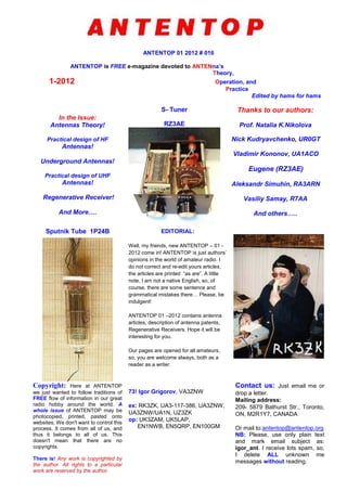
- 1. ANTENTOP 01 2012 # 016 ANTENTOP is FREE e-magazine devoted to ANTENna’s Theory, 1-2012 Operation, and Practice Edited by hams for hams In the Issue: Antennas Theory! Practical design of HF Antennas! Underground Antennas! Practical design of UHF Antennas! Regenerative Receiver! And More…. S- Tuner RZ3AE Thanks to our authors: Prof. Natalia K.Nikolova Nick Kudryavchenko, UR0GT Vladimir Kononov, UA1ACO Eugene (RZ3AE) Aleksandr Simuhin, RA3ARN Vasiliy Samay, R7AA And others….. Sputnik Tube 1P24B EDITORIAL: Well, my friends, new ANTENTOP – 01 - 2012 come in! ANTENTOP is just authors’ opinions in the world of amateur radio. I do not correct and re-edit yours articles, the articles are printed “as are”. A little note, I am not a native English, so, of course, there are some sentence and grammatical mistakes there… Please, be indulgent! ANTENTOP 01 –2012 contains antenna articles, description of antenna patents, Regenerative Receivers. Hope it will be interesting for you. Our pages are opened for all amateurs, so, you are welcome always, both as a reader as a writer. Copyright: Here at ANTENTOP we just wanted to follow traditions of FREE flow of information in our great radio hobby around the world. A whole issue of ANTENTOP may be photocopied, printed, pasted onto websites. We don't want to control this process. It comes from all of us, and thus it belongs to all of us. This doesn't mean that there are no copyrights. There is! Any work is copyrighted by the author. All rights to a particular work are reserved by the author. 73! Igor Grigorov, VA3ZNW ex: RK3ZK, UA3-117-386, UA3ZNW, UA3ZNW/UA1N, UZ3ZK op: UK3ZAM, UK5LAP, EN1NWB, EN5QRP, EN100GM Contact us: Just email me or drop a letter. Mailing address: 209- 5879 Bathurst Str., Toronto, ON, M2R1Y7, CANADA Or mail to:antentop@antentop.org NB: Please, use only plain text and mark email subject as: igor_ant. I receive lots spam, so, I delete ALL unknown me messages without reading.
- 2. ANTENTOP is FREE e-magazine, available FREE at http://www.antentop.org/ ANTENTOP- 01- 2012, # 016 Editorial Welcome to ANTENTOP, FREE e - magazine! ANTENTOP is FREE e- magazine, made in PDF, devoted to antennas and amateur radio. Everyone may share his experience with others hams on the pages. Your opinions and articles are published without any changes, as I know, every your word has the mean. Every issue of ANTENTOP is going to have 100 pages and this one will be paste in whole on the site. Preview's files will be removed in this case. I do not know what a term for one issue will need, may be 8- 10 month or so. A whole issue of ANTENTOP hold nearly 10 MB. A little note, I am not a native English, so, of course, there are some sentence and grammatical mistakes there… Please, be indulgent! Preview: Some articles from "cooking" issue will be pasted for preview on this site, others no. Because, as I think, it must be something mysterious in every issue. Publishing: If you have something for share with your friends, and if you want to do it FREE, just send me an email. Also, if you want to offer for publishing any stuff from your website, you are welcome! Your opinion is important for me, so, contact if you want to say something! Copyright Note: Dear friends, please, note, I respect Copyright. Always, when I want to use some stuff for ANTENTOP, I ask owners about it. But… sometimes my efforts are failed. I have some very interesting stuff from closed websites, but I can not go to touch with their owners… as well as I have no response on some my emails from some owners. I have a big collection of pictures, I have got the pictures and stuff in others ways, from FREE websites, from commercial CDs, intended for FREE using, and so on... I use to the pictures (and seldom, some stuff from closed websites) in ANTENTOP. If the owners still are alive, please, contact with me, I immediately remove any Copyright stuff, or, if it is necessary, all needed references will be made there. I do not know, why the owners do not response me. Are they still alive? Do their companies are a bankrupt? Or do they move anywhere? Where they are in the end? Business Advertising: ANTENTOP is not a commercial magazine. Authors and I (Igor Grigorov, the editor of the magazine) do not get any profit from the issue. But off course, I do not mention from commercial ads in ANTENTOP. It allows me to do the magazine in most great way, allows me to pay some money for authors to compensate their hard work. I have lots interesting stuff in Russian, and owners of the stuff agree to publish the stuff in ANTENTOP… but I have no enough time to translate the interesting stuff in English, however I may pay money to translators, and, they will do this work, and we will see lots interesting articles there. So, if you want to put a commercial advertisement in ANTENTOP, please contact with me. A commercial advertisement will do ANTENTOP even greater interesting and various! I hope, readers do not mention against such commercial ads. Book Advertising: I believe that Book Advertising is a noncommercial advertisement. So, Book Advertising is FREE at ANTENTOP. Contact with me for details. Email: igor.grigorov@gmail.com subject: igor_ant NB: Please, use only plain text and mark email subject as: igor_ant. I receive lots spam and viruses, so, I delete ALL unknown me messages without reading. 73! Igor Grigorov, VA3ZNW ex: UA3-117-386, UA3ZNW, UA3ZNW/UA1N, UZ3ZK, RK3ZK op: UK3ZAM, UK5LAP,EN1NWB, EN5QRP, EN100GM http://www.antentop.org/ Editorial
- 3. ANTENTOP- 01- 2012, # 016 Table of Contents Table of Contents Antenna Theory Page 1 Reflector Antennas: by: Prof. Natalia K. Nikolova Dear friends, I would like to give to you an interesting and reliable antenna theory. Hours searching in the web gave me lots theoretical information about antennas. Really, at first I did not know what information chose for ANTENTOP. Now I want to present to you one more very interesting Lecture 14 - it is a Lecture Reflector Antennas. I believe, you cannot find such info anywhere for free! Very interesting and very useful info for every ham, for every radio- engineer. High-gain antennas are required for long-distance radiocommunications (radio-relay links and satellite links), highresolution radars, radioastronomy, etc. Reflector systems are probably the most widely used high-gain antennas… 5- 31 HF- Antenna Practice 2 Off Center Dipole Fed Antenna for 80- 40- 20- 15- and 10- meter Bands : Credit Line: Radio and TV-news, June, 1958 Just description of an Off Center Dipole Fed Antenna for 80-, 40-, 20-, 15- and 10- meter Bands... 32 3 Ground Plane Antenna for 40, 20, 15 and 10- meter Bands: by: Vsevolod Vorob'ev, UA3FE, Moscow. Credit Line: Radio 1958, #6, pp.: 30, 31, 36 Originally the antenna was used (and described) by polish ham Kahlickiy in 1946 year. The advantage of the antenna is that only one relay is used to switch the four working bands of the antenna... 33- 36 4 Vertical Antenna for 80-, 40-, 20-, 15- and 10- meter Bands: by: Yuri Medinets, UB5UG, Kiev :Credit Line: Radio # 9, 1960, p. 44 The antenna is designed to work at 80-, 40-, 20-, 15- and 10- meter Bands without any commutation in the ATU (Antenna Tuning Unit). It is reached with the help of ATU made on the base of an open stub... 37- 38 Page 1 http://www.antentop.org/
- 4. ANTENTOP- 01- 2012, # 016 Table of Contents Table of Contents Page 5 Shortened Antenna for the 160- meter Band: by: Aleksandr Simuhin, RA3ARN At my QTH I had no space for full sized dipole antenna for the 160- meter. So what I may install there it was only a shortened antenna. After dig out in the internet and books and tried out different antennas at my location I found the antenna that works for me... 39- 40 6 Ground Plane for the 40,-30,-20 and 17- meter Bands: by: Vasiliy Samay, R7AA) The antenna is very simple. It is just vertical radiator in 10- meter length that is matched at the each working band by its own matching unit that is switched on with help of relay. However to the design I came not straight away… 41- 45 7 EH Antenna for the 20- meter Band: by: Vladimir Kononov, UA1ACO, St. Petersburg Below step by step will be described how to make a EH- Antenna for the 20- meter Band. So if you are ready- go ahead ... 46- 54 8 Delta Loop for 40- and 20- meter Band: By: Nikolay Kudryavchenko, UR0GT Antenna has good SWR on both 40 and 20- meter Bands. Antenna placed on distance 2- meter above real ground. Input impedances of the antenna on both bands depend on distance above the ground and condition of the ground... 55- 57 9 Half Loop Antenna for the 80-, 40,- 20,- and 15- meter Bands: By: Nikolay Kudryavchenko, UR0GT It is very simple and efficiency antenna that works in several amateurs bands- 80,- 40,- 20,- and 15- meters. The antenna has input impedance 75 - Ohm... 58- 62 10 3- Elements YAGI Antenna for the 20- meter Band: By: Nikolay Kudryavchenko, UR0GT It is very simple and efficiency YAGI antenna with wide pass band. Antenna has input impedance 50- Ohm. UR0GT - Match is used for matching the antenna with a coaxial cable... 63- 64 Page 2 http://www.antentop.org/
- 5. ANTENTOP- 01- 2012, # 016 Table of Contents Table of Contents UHF- Antenna Practice 11 Ground Plane for AVIA Band: By: Nikolay Kudryavchenko, UR0GT Some receivers for AVIA-Band (118- 136- MHz) are designed for 75- Ohm -antennas. Below described simple Ground Plane antenna for the band that has input impedance 75-Ohm at good SWR on 118- 136- MHz..... 65- 66 12 Antenna for Two- meter Band with Cardioid Diagram Directivity: By: Nikolay Kudryavchenko, UR0GT The antenna has Cardioid Diagram Directivity. There are some special cases when such diagram required to be used... 67- 68 13 Discone Antenna for the 2- meter Band: by: by V. Bataev Credit Line: Radio # 8, 1958 Antenna was designed for the 2- meter Band. The antenna combined the all advantages of the discone antenna with the simplicity of the design... 69- 70 Receiving Magnetic Loop Antennas 14 Two Receiving Magnetic Loop Antennas from Old Magazines Very often it is possible to find something interesting and unusual while going around old magazines. Below there are two interesting design of the Magnetic Loop Antenna... 71 Tuners 15 S- Tuner: by: Eugene (RZ3AE) S- Tuner provides matching of asymmetrical output of a transceiver with symmetrical feeder line. Symmetrical feeder line (as usual it is two- wire ladder line or two- wire line with plastic insulation) used to feed symmetrical dipole antennas... 72- 74 Page 3 http://www.antentop.org/
- 6. ANTENTOP- 01- 2012, # 016 Table of Contents Table of Contents Page Underground Antennas 16 Underground Antennas: Credit Line: CQHAM.RU. Forum: Underground Antennas Below there are pasted some messages from the topic on Underground Antennas from the ham- radio forum on CQHAM.RU... 75- 80 17 Underground Can Antenna: Credit Line: Forum at http://russianarms.mybb.ru/ At articles about Underground Antennas that are published at Antentop there are pictures of Underground Antennas that look like a giant plate or giant up- down can. What is inside of the monster? At Antentop there were several version of the inside design. Below one more version and some more pictures of the underground cans are included... 81- 82 Regenerative Receivers 18 Regenerative Receiver Audion with 1ZH24B Tubes: by: Andrey Bessonov, Chelaybinsk Audion is an old regenerative receiver that was produced in pre WWII German. The shown below receiver is a bit similar to the old Audion on the schematic... 83- 84 19 Autodyne Synchronous Regenerative Receiver: by: Sergey Starchak Described an original Autodyne Synchronous Regenerative Receiver that was made and tested by Sergey Starchak.... 85- 86 20 Regenerative Receiver on Pencil (Sputnik) Tubes: by: V.V. Voznyuk Just schematics of the simple regenerative receivers made on the Pencil (Sputnik) tubes... 87- 88 Page 4 http://www.antentop.org/
- 7. ANTENTOP- 01- 2012, # 016 Table of Contents Table of Contents Page History Data 21 Pencil Tubes: by: V.Sukhanov, A. Kireev Credit Line: Radio # 10, 1960, pp.: 49- 52 Below there are described some main schematics on the miniature "pencil" tubes. The schematics came to us from the far 50- 60-s of the 20- Century. The schematics with pencil tubes were used at the radio equipment that was installed practically anywhere - from tank and submarine up to space ship.. . 89-92 22 Data for the Soviet Sputnik (Pencil) Tubes Just Data for the Sputnik Pencil Tubes… 93 Towers 23 Self- Supporting Tower: by: B. Derkachev: Credit Line: Radio 1957, #1, p. 27 Design of a simple self- supporting tower. 98 Patents 24 Broad Band Antenna (Discone Antenna): By Armig G. Kandoian Just the famous patent on to discone antenna filled by Armig G. Kandoian 94- 97 25 Josef Fuchs (OE1JF) Antenna: Patent Description Dr. Josef Fuchs, OE1JF, Austrian Radio Amateur, was the first who described the Monoband Endfeed Half Dipole Antenna in 1928. Later the antenna got name "Fuchs Antenna." Just Patent Description 99- 100 Page 4.1 http://www.antentop.org/
- 8. ANTENTOP- 01- 2012, # 016 Reflector Antennas Feel Yourself a Student! Dear friends, I would like to give to you an interesting and reliable antenna theory. Hours searching in the web gave me lots theoretical information about antennas. Really, at first I did not know what information to choose for ANTENTOP. Finally, I stopped on lectures “Modern Antennas in Wireless Telecommunications” written by Prof. Natalia K. Nikolova from McMaster University, Hamilton, Canada. You ask me: Why? Well, I have read many textbooks on Antennas, both, as in Russian as in English. So, I have the possibility to compare different textbook, and I think, that the lectures give knowledge in antenna field in great way. Here first lecture “Introduction into Antenna Study” is here. Next issues of ANTENTOP will contain some other lectures. So, feel yourself a student! Go to Antenna Studies! I.G. My Friends, the above placed Intro was given at ANTENTOP- 01- 2003 to Antennas Lectures. Now I know, that the Lecture is one of popular topics of ANTENTOP. Every Antenna Lecture was downloaded more than 1000 times! So, feel yourself a student! Go to Antenna Studies! I.G. McMaster University Hall Prof. Natalia K. Nikolova Reflector Antennas High-gain antennas are required for long-distance radio communications (radio-relay links and satellite links), highresolution radars, radioastronomy, etc. Reflector systems are probably the most widely used high-gain antennas…by Prof. Natalia K. Nikolova www.antentop.org Page-5 Now I want to present to you one more very interesting Lecture 14 - it is a LectureReflectorAntennas. I believe, you cannot find such info anywhere for free! Very interesting and veryuseful info for every ham, for every radio- engineer.
- 9. ANTENTOP- 01- 2012, # 016 Reflector Antennas www.antentop.org Page-06
- 10. ANTENTOP- 01- 2012, # 016 Reflector Antennas www.antentop.org Page-07
- 11. ANTENTOP- 01- 2012, # 016 Reflector Antennas www.antentop.org Page-08
- 12. ANTENTOP- 01- 2012, # 016 Reflector Antennas www.antentop.org Page-09
- 13. ANTENTOP- 01- 2012, # 016 Reflector Antennas www.antentop.org Page-10
- 14. ANTENTOP- 01- 2012, # 016 Reflector Antennas www.antentop.org Page-11
- 15. ANTENTOP- 01- 2012, # 016 Reflector Antennas www.antentop.org Page-12
- 16. ANTENTOP- 01- 2012, # 016 Reflector Antennas www.antentop.org Page-13
- 17. ANTENTOP- 01- 2012, # 016 Reflector Antennas www.antentop.org Page-14
- 18. ANTENTOP- 01- 2012, # 016 Reflector Antennas www.antentop.org Page-15
- 19. ANTENTOP- 01- 2012, # 016 Reflector Antennas www.antentop.org Page-16
- 20. ANTENTOP- 01- 2012, # 016 Reflector Antennas www.antentop.org Page-17
- 21. ANTENTOP- 01- 2012, # 016 Reflector Antennas www.antentop.org Page-18
- 22. ANTENTOP- 01- 2012, # 016 Reflector Antennas www.antentop.org Page-19
- 23. ANTENTOP- 01- 2012, # 016 Reflector Antennas www.antentop.org Page-20
- 24. ANTENTOP- 01- 2012, # 016 Reflector Antennas www.antentop.org Page-21
- 25. ANTENTOP- 01- 2012, # 016 Reflector Antennas www.antentop.org Page-22
- 26. ANTENTOP- 01- 2012, # 016 Reflector Antennas www.antentop.org Page-23
- 27. ANTENTOP- 01- 2012, # 016 Reflector Antennas www.antentop.org Page-24
- 28. ANTENTOP- 01- 2012, # 016 Reflector Antennas www.antentop.org Page-25
- 29. ANTENTOP- 01- 2012, # 016 Reflector Antennas www.antentop.org Page-26
- 30. ANTENTOP- 01- 2012, # 016 Reflector Antennas www.antentop.org Page-27
- 31. ANTENTOP- 01- 2012, # 016 Reflector Antennas www.antentop.org Page-28
- 32. ANTENTOP- 01- 2012, # 016 Reflector Antennas www.antentop.org Page-29
- 33. ANTENTOP- 01- 2012, # 016 Reflector Antennas www.antentop.org Page-30
- 34. ANTENTOP- 01- 2012, # 016 Reflector Antennas www.antentop.org Page-31
- 35. ANTENTOP- 01- 2012, # 016 Off Center Dipole Fed Antenna for 80- 40- 20- 15- and 10- meter Bands Credit Line: Radio and TV-news, June, 1958 A Four- Bands Off-Center Dipole Antenna (for 80- 40- 20- and 10- meter Bands) is well known among radio amateurs. However, the antenna cold be tuned to the fifth band (15- meter) just by adding of two 2 insulators and two closed stub with electrical length lambda/4 at the 15- meter Band. Figure 1 shows the antenna. The parts of the antenna, that are located before the insulators (from feeding terminals), work on the 15- meter Band. The lambda/4 closed stubs cut off from the antenna the parts of the antenna located after insulators on the 15- meter Band. At the other bands all parts of the antenna are worked because the stubs included in the overall antenna length. The lambda/4 closed stubs made from a ribbon two wire ladder line. Length each of the stub is 4.85- meter. One end of the stub closed another end of the Radio and TV-news, June, 1958 Front Cover stub soldered to the antenna. Length of the wires between antenna and the stub is 15- cm. Stub should be tuned to the 15- meter Band (for example with help of a DIP-Meter) before the installation into the antenna. Both stubs should be tuned onto the same frequency. The antenna worked great at the all five bands. Figure 1 Off Centre Dipole Fed Antenna for 80- 40- 20- 15- and 10- meter Bands www.antentop.org Page-32
- 36. ANTENTOP- 01- 2012, # 016 Ground Plane Antenna for 40, 20, 15 and 10- meter Bands Vsevolod Vorob’ev, UA3FE, Moscow Credit Line: Radio 1958, #6, pp.: 30, 31, 36 Originally the antenna was used (and described) by polish ham Kahlickiy in 1946 year. The advantage of the antenna is that only one relay is used to switch the four working bands of the antenna. Vertical radiator of the antenna is grounded so the antenna may be used near lightning storm period. To understand how the antenna is matched and tuned we need to review some pieces of the antenna theory. Let’s see to the Figure 1 and Figure 2. Figure 1 shows “active antenna input resistance” vs “ratio antenna length/working wavelength”. Figure 2 shows “reactance of antenna input impedance” vs “ratio antenna length/working wavelength”. The diagrams are simulated for vertical radiator placed above ideal ground. However, 4- counterpoises with length equal to the vertical part of the antenna are satisfactory analogue of an ideal ground. Radio # 6, 1958 Based on the Figure 1 and Figure 2 it is possible to find antenna impedance of the vertical radiator Vs of the length of the vertical. When the physical length of the vertical radiator is the value that is multiplied by the 0.25 lambda, the input impedance of the radiator is only resistive. Radiator has inductance reactance in the input impedance at the physical length from 0.25 to 0.5- lambda. Radiator has capacitance reactance in the input impedance at the physical length from 0.5 to 0.75- lambda. And so on. Header of the Article www.antentop.org Page-33
- 37. ANTENTOP- 01- 2012, # 016 Ground Plane Antenna for 40, 20, 15 and 10- meter Bands Figure 1 “Active Antenna Input Resistance” Vs “Ratio Antenna Length/Working Wavelength” Figure 2 “Reactance of Antenna Input Impedance” Vs “Ratio Antenna Length/Working Wavelength” However, for to any antenna to radiate efficiently this one should be matched with the feeder. As usual it is not complicated to match an antenna in narrow frequency band. Antenna is matched with the feeder with help of a circuit that commonly consist of from capacitors and inductors. The circuit that is called Antenna Tuning Unit does compensation of the antenna reactance and transforms antenna resistance to the feeder. However it is very hard to find such ATU that would be worked at several bands without changing parameters of its parts. But it was found off for the antenna! Figure 3 shows the ATU. Figure 3 ATU of the Ground Plane Antenna for 40, 20, 15 and 10- meter Bands www.antentop.org Page-34
- 38. ANTENTOP- 01- 2012, # 016 Ground Plane Antenna for 40, 20, 15 and 10- meter Bands The ATU has a closed stub made of a coaxial cable with electrical length 1.25- lambda for the 15- meter Band. At the band the stub has high resistance impedance and antenna is tuned with help L1 and C1. At the 20- meter band the stub has capacitance impedance what is needed to match the antenna at the band. At 10- meter band the stub has inductance impedance what is needed to match the antenna at the band. At the 40- meters band a lengthening inductor L2 is used to match the antenna. The inductor is closed with help of Relay K1 at the other bands. Good match of the antenna is possible only on one band- 15- meter. At the other bands the match is only satisfactory. Figure 4 shows design of the antenna base with ATU. ATU should be placed into weather- proofed plastic or metal box. Item 1: Porcelain Base Insulator Item 2: Span- Counterpoise Item 3: Lengthening Inductor L2 Item 4: Radiator Base Item 5: Radiator Item 6: Antenna Support Base Tube Item 7: Feeder and Closed Stub Four counterpoises were used with the antenna. Each counterpoise had length 530- cm, diameter 2- mm and was installed at 45- degree to the Antenna Support Base Tube. Metal roof may be used instead of the counterpoises in case if the antenna is installed above such roof. Vertical radiator made of from an aluminum tube in diameter 4- cm and has length 530- cm. Original ATU was calculated to match the antenna with coaxial cable 88- Ohm. Table 1 gives data for the ATU for coaxial cables 88-, 50- and 75- Ohm. Figure 4 Design of the antenna base with ATU www.antentop.org Page-35
- 39. ANTENTOP- 01- 2012, # 016 Ground Plane Antenna for 40, 20, 15 and 10- meter Bands Table 1 Data for the ATU for Coaxial Cables 88-, 50- and 75- Ohm Coaxial 88- Ohm Coaxial 75- Ohm Coaxial 50- Ohm L1, micro- Henry 0.825 0.8 0.7 L2, micro- Henry 6.6 7.0 6.3 C1, pF 64 68 83 Length of the closed Stub, meter 10.7 11.4 11.4 SWR 10-meter 1.1 1.12 4.0 15- meter 1.0 1.0 1.0 20- meter 2.2 2.22 1.7 40- meter 3.6 2.8 1.05 Photo from WW II. Belorussian partisans listen to Radio Moscow www.antentop.org Page-36
- 40. ANTENTOP- 01- 2012, # 016 Vertical Antenna for 80-, 40-, 20-, 15- and 10- meter Bands Yuri Medinets, UB5UG, Kiev Credit Line: Radio # 9, 1960, p. 44 The antenna is designed to work at 80-, 40-, 20-, 15- and 10- meter Bands without any commutation in the ATU (Antenna Tuning Unit). It is reached with the help of ATU made on the base of an open stub that is connected to the vertical radiator and counterpoises. The stub made from a coaxial cable and has electrical length 0.5- lambda at the 80- meter Band. Figure 1 Current distribution along the antenna and the Stub Radio # 9, 1960 Front Cover Is it possible to find terminals at the stub where matching on the amateurs Bands 40-, 20-, 15- and 10- meter is rather possible. Current distribution along the antenna and the Stub is shown on the Figure 1. Design of the antenna is shown on the Figure 2. Length of the Vertical radiator and length of the stub is optimized for good diagram directivity for all working bands. Header of the Article www.antentop.org Page-37
- 41. ANTENTOP- 01- 2012, # 016 Vertical Antenna for 80-, 40-, 20-, 15- and 10- meter Bands PK-1- Russian Coaxial cable 77- Ohm PK3- 3- Russian Coaxial cable 75- Ohm Feeding terminals are chosen to best match of the antenna at all working bands. For the feeding terminals there were obtained: SWR at the 80- meter Band- 3… 3.5; SWR at the 40-, 20- and 15- meter Bands- no more the 1.5; SWR at the 10- meter Band- near 2. Antenna made as an usual Ground plane antenna. Vertical Radiator made of aluminum tubes in diameter 20- 35- mm. Four counterpoises attached to the mast of the antenna with help of nuts’ insulators. Stub of the antenna is radiated so it needs to be away from any conductive subjects. The antenna was tested at the UB5UG radio station from July 1960 and it was obtained quarter good results. Antenna works fine at 40- and 20- meter Bands. At the 10- and 15- meter Bands the antenna works satisfactory (DD of the antenna is radiated at too high angles). At the 80- meters the antenna works also quarter satisfactory. Figure 2 Design of the Vertical Antenna for 80-, 40-, 20-, 15- and 10- meter Spiral Antenna from UN7GZZ Credit Line: http://forum.qrz.ru/thread22310-253.html www.antentop.org Page-38
- 42. ANTENTOP- 01- 2012, # 016 Shortened Antenna for the 160- meter Band Aleksandr Simuhin, RA3ARN Credit Line: http://www.cqham.ru/ At my QTH I had no space for full sized dipole antenna for the 160- meter. So what I may install there it was only a shortened antenna. After dig out in the internet and books and tried out different antennas at my location I found the antenna that works for me. The antenna was made in 2008. Several years in the Air on the 160- meter Band with the antenna and 15- watts TX gave good reference for the antenna. Figure 1 shows the Shortened Antenna. Design of the antenna: It is symmetrical antenna. However it is possible to make asymmetrical one. Antenna may be installed in line similar to usual dipole antenna or may be installed similar to I.V. antenna. Aleksandr Simuhin, RA3ARN Figure 1 Shortened Antenna for the 160- meter Band www.antentop.org Page-39
- 43. ANTENTOP- 01- 2012, # 016 Shortened Antenna for the 160- meter Band RA3ARN installed the antenna similar to I.V. antenna. It was used 10-meter wooden mast for the antenna. Lower ends of the antenna were at 3- meters above the ground. Antenna has two wires item 1 and item 2 with constant length 11- meter each. Length of the wires item 3 and item 4 may vary from 18 to 15- meters when antenna is tuned up. Antenna is matched with a coaxial cable with help of a length of a two wire open line – item 5. It is 450- Ohm open line in length 12.5- meters. Coaxial cable 50 or 75- Ohm may be used to feed the antenna. Antenna is lengthened with help of coils item 6 and item 7. The coils made from length of an Ethernet Cable, 17 meter each. RA3ARN used Ethernet Cable with mark on it: NEXANS UTP KATEGORY 5E TIA 568-5EC VERIFIED №11168 4PR 24AWG SU3505. Almost any 4- pair Ethernet Cable may be used for the coils. Figure 2 shows diagram of the coil. All twisted pairs are connected in serial. Then the cable was coiled in a hank of 40- cm diameter. Soldered ends were protected from weather conditions with help of a thermo- shrink tube. Figure 2 Diagram of the lengthen coil. Overall length of the half of the dipole antenna is 164 meters. Overall length of the all dipole antenna is 328 meters. Antenna had SWR 1.08 at 160 meters. Second resonance was at 20 meters with SWR 1.5 within 40- kHz. Antenna may be tuned to another amateur’s bands with help of a simple ATU. Antenna worked fine for several years. It was used 15- Wtts at the 160- meter and 800- Wtts at the 80-40- and 20- meter Bands. Used the method of the shortening it is possible to remake almost any wire antenna. For example, existing I.V. for the 80- meter may be easy turned on to a multi- band antenna. 73! RA3ARN www.antentop.org Page-40
- 44. ANTENTOP- 01- 2012, # 016 Ground Plane for the 40,-30,-20 and 17- meter Bands By: Vasiliy Samay, R7AA Credit Line: http://news.cqham.ru/articles/detail.phtml?id=1076 The antenna is very simple. It is just vertical radiator in 10- meter length that is matched at the each working band by its own matching unit that is switched on with help of relay. However to the design I came not straight away. There were tried several multiband antennas (for example, antennas from References 1 and 2) but for some reason no one of them did not satisfied me. I could not get good SWR at each of desirable working bands of the antennas. Friend of mine, UA7A, ex UA6CW, advised to me to use the described below antenna. He helped to me to calculate matching circuits for the antenna. Figure 1 shows schematic of the antenna. Figure 2 shows schematic of the matching units for 40,- 30,- 20 and 17- meter Bands. To eliminate static from the antenna the vertical radiator is grounded through pair resistors in 430- kOhm/2- Wtts. Figure 2 Matching units for 40,- 30,- 20 and 17- meter Bands. www.antentop.org Page-41
- 45. ANTENTOP- 01- 2012, # 016 Ground Plane for the 40,-30,-20 and 17- meter Bands Figure 1 Ground Plane for the 40,- 30,- 20 and 17- meter Bands www.antentop.org Page-42
- 46. ANTENTOP- 01- 2012, # 016 Ground Plane for the 40,-30,-20 and 17- meter Bands Table 1 shows data for the matching unit. All inductors are coiled by wire in 2- mm diameter (12- AWG). Inductors are air- winding. Diameter of each inductor is 40- mm. Gap between coils is 3- 5-mm. The gap should be defined at the tuning of the antenna. High- voltage ex- USSR capacitors K15U-1 are used in the matching unit. Vacuum ex- USSR relay V1V did switching on the matching circuit. All matching circuits were sitting in aluminum box by dimension 330x200x130- mm. Figure 3 shows the design of the box. (There are matching circuits for the 80/75- meter Band inside the matching box. However, the antenna could not provide satisfaction operation on the bands. So I did not use the antenna on the bands) Ground Plane. General view Table 1 Data for parts for the matching unit Band, m Inductor, turns Capacitor, pF 40 3 300 (3X100- pF) 30 8 118 (100- pF + 18- pF) 20 8.5 22 17 5.3 112 (100- pF+ 18- pF) www.antentop.org Page-43
- 47. ANTENTOP- 01- 2012, # 016 Ground Plane for the 40,-30,-20 and 17- meter Bands Figure 3 Box with matching circuits Relay V1V Ground Plane. Radials www.antentop.org Page-44
- 48. ANTENTOP- 01- 2012, # 016 Ground Plane for the 40,-30,-20 and 17- meter Bands Antenna may tune in the resonance by length of the radials and changing inductance of the inductors (by squeeze/stretch). Table 2 shows data for the antenna measured by MFJ- 259-B. There are shown data for two antenna locations at the roof. “Variant 1” shows data for initial installation of the antenna. Then antenna for some reason was relocated to other place. “Variant 2” shows the data for the other installation of the antenna. The places were almost equal to each other. The difference is in the length of the coaxial cable going from my transceiver to the antenna. Length of the cable at “Variant 1” was 18- meter. Length of the cable at “Variant 2” was 40.6- meter. References 1. http://www.dl2kq.de/ant/3-3.htm 2. http://www.antentop.org/ua1dz.htm Table 2 Data for Two Variants of Installation of the Ground Plane Antenna Variant 1 Variant 2 F, MHz SWR R X F, MHz SWR R X 18.200 1.1 52 7 18.170 1.0 49 3 18.068 1.2 58 8 18.068 1.1 56 4 14.100 1.1 44 3 14.110 1.0 50 4 14.000 1.2 46 8 14.000 1.2 56 7 14.200 1.2 41 0 14.200 1.1 46 6 14.300 1.3 36 0 14.300 1.3 44 11 14.370 1.5 33 0 14.350 1.3 44 14 10.110 1.0 49 3 10.100 1.1 46 7 1.150 1.1 46 4 10.150 1.1 45 4 7.000 1.1 49 6 7.000 1.2 41 6 7.100 1.1 45 4 7.100 1.0 50 1 7.200 1.4 37 8 7.200 1.3 62 7 Capacitors K15U-1 Ground Plane. Box with matching circuits www.antentop.org Page-45
- 49. ANTENTOP- 01- 2012, # 016 EH Antenna for the 20- meter Band Vladimir Kononov, UA1ACO, St. Petersburg Credit Line: http://ehant.qrz.ru/exp_eh1.htm Below step by step will be described how to make a EH- Antenna for the 20- meter Band. So if you are ready- go ahead with me! At the beginning we have to visit nearest Building Materials Store (Note I.G.: something like Home Depot). For making of the antenna you need to buy: Polypropylene Tube РР-Н 32х1,8 DIN 4102 B1 (dia 32-mm and length 50- cm). Cap for the Tube 32РР S-16 (just to fit to close the tube). Copper foil two pieces by dimension 160-mm x 115- mm each (Note I.G.: In Canada I have seen such foil in local Craft Store). UA1ACO Several screw for plastic (wood) in length 10- 15-mm and several screw in dia 3- mm and length 10- 15- mm with nuts. 3- meter length of insulated wire in dia 2-mm (12- 13- AWG) (Note I.G.: For Canada: Local Craft Store, Dollorama, Sayal, A- Z- Electronics). . If you could find buy a 2- meter length of main cable with stranded wires in 1.5- mm dia (14-16- AWG). Do not forget find an RF- Socket in a special shop or your stock. For tuning of the antenna you will need: SWR- meter.Field Strength Meter. Spectrograph Instead of Spectrograph you may to use: Powerful RF Generator or RF-Generator with RF- Bridge- for example, similar to MFJ- 259B. For experimenting with the antenna you will need a Q- Meter and C- Meter. So all above mention parts are sitting on the desk. It is possible to make the EH- Antenna. www.antentop.org Page-46
- 50. ANTENTOP- 01- 2012, # 016 EH Antenna for the 20- meter Band Making the EH- Antenna. Figure 1 shows design of the antenna. Before the making of the antenna, please, carefully read all the article. Special attention should be taken to places that printed in the red color. Take two copper sheets. Put it on to a plane surface. Clean by sandpaper sides in 160- mm long. Tin the sides by a soldering iron (100- Wtt would be good stuff). Clean up the flux. Tinned sheets roll up by the Polypropylene Tube on the plane surface. Figure 1 Design of the EH- Antenna for the 20- meter Band www.antentop.org Page-47
- 51. ANTENTOP- 01- 2012, # 016 EH Antenna for the 20- meter Band Fist copper sheet turns around of the Polypropylene Tube and temporary hold by a length of wire. Distance from the upper end of the tube to the foil should be 15- 20-mm. Take hot soldering iron and solder the sheet in 3- places. You need to do it fast because the plastic tube may be melted. Take wire for the phase inductor. Put wire to the seam and do soldering the foil on the full length. Phase inductor has 2- 3 (3 better) turns of the insulated wire. Turn around the tube coils of the inductor. Lower end of the inductor is inserted into the hole in dia 2-mm onto the tube. Do not forget to tin the end. Figure 2 shows soldering of the inductor to the upper copper cylinder. Figure 3 shows the ready phase inductor. Figure 2 Soldering of the Inductor to the Upper Copper Cylinder Figure 3 Ready Phase Inductor Take the second copper sheet. Do with it the same things as with the first one (to turn around of the plastic tube hold by pieces of wire and do soldering in several places). Pay attention that the second (lower) cylinder should be placed on the distance apart of the first cylinder equal to diameter of the tube. At our case it is 32- mm (see Figure 1). Next step is to measure the capacity between the cylinders. I used to a surplus Russian device E9- 5. Figure 4 shows the measurement. At the design of the EH- Antenna the capacity between the cylinders should be near 7- pF. Knowing of the value is needed for us to calculate (according to W5QJR reference book) a tuning inductor. Below I give you a calculated by me data for the inductor. Next step is to make the tuning inductor. The inductor is coiled by enamel strand wire in diameter 2- mm (12- AWG). Numbers of turns are 26 (calculated value) but I recommend to coil 28- 29 turns. Figure 4 Measure the Capacity between the Cylinders It should be done for purpose of the tuning of the EH – Antenna because it is easy to remove the coils then to add those ones. www.antentop.org Page-48
- 52. ANTENTOP- 01- 2012, # 016 EH Antenna for the 20- meter Band So, take the wire, straighten the wire. Take distance in 32- mm apart of the lower end of the lower cylinder. Do hole in 1.5- 2- mm in the plastic tube. It is possible to do with usual soldering iron. Tin one of the end of the wire on length 10- mm. Insert the tinned end into the hole. Coil 23- turns. (1) Do loop from the wire. Tin the loop. (2) Do one more turn. Do loop from the wire. Tin the loop. (3) Do one more turn. Do loop from the wire. Tin the loop. (4) Do one more turn. Do loop from the wire. Tin the loop. Then coil the last three turns. Then do hole in the plastic tube and insert in the hole the wire. Figure 5 shows the tapped tuning inductor. My advice: Coil first and last 3- turns with gap in 3- 4- mm between the turns. It would be useful at final tuning of the antenna. So the inductor should be look like it is shown on the Figure 6. Figure 5 Tapped Tuning inductor Figure 6 Tuning inductor with Gap between the Coils Almost all parts are installed on the tube. Antenna almost is ready! Figure 7 shows the antenna. Figure 7 EH- Antenna 1. Copper Cylinders 2. Phase Inductor 3. Tuning Inductor 4. Tuning Part of the Inductor 5. Plastic Tube www.antentop.org Page-49
- 53. ANTENTOP- 01- 2012, # 016 EH Antenna for the 20- meter Band Next step is to connect the antenna parts between each other. The stage requires patient and attention. At first, connect by wire in plastic insulation the upper end of the lower cylinder with lower end of the tuning inductor. (See Figure 1) For this connection do holes in dia 2- mm near the upper end of the lower cylinder and lower end of the tuning inductor. Take the length of wire that a little more the distance between the holes. The wire should go inside the tube and the wire should touch by all it length the inner surface of the tube. Tin ends of the wire. Bend the tinned ends of the wire onto 90- degree. Then insert the tinned ends of the wire into holes. Use all tools that you can find or make. I personally used a wood stick with a slot. An end of the wire was inserted to the slot then the end was inserted into the hole. After that the end was bended and soldered to the cylinder. Then next end of the wire was inserted into the hole and straight away bended and soldered to the tuning inductor. At second, connect by wire in plastic insulation the lower end of the phase inductor with upper end of the tuning inductor. (See Figure 1) Preliminary do the same things as was done with the first wire. However the wire should go into center of the tube. You may use some kind of spreader to keep the distance equal inside the tube. Figure 8 shows the wires inside of the tube. At third, last step to make the EH- Antenna. Install the cap with an RF- socket and an input inductor. Figure 9 shows the cap. Do holes for fastened RF- Socket by screw with nuts and install this one. Figure 10 shows the cap with the RF- Socket. Cut half part of plastic from the cap, install wires and input inductor. Figure 11 shows the cap with the RF- Socket and the input inductor. Well, do not hurry to install the input inductor it should be installed after a preliminarily tuning of the antenna. The inductor helps get the minimum SWR in the antenna. Tuning inductor may contain 5- 7 turns. Diameter of the inductor is 12- 15- mm. It made by wire in plastic insulation (similar wire that was used for the phase inductor). The inductor must be placed perpendicularly to axis of the plastic tube. Figure 8 Wires inside of the Tube Figure 9 Tube Cap Figure 10 Tube Cap with RF- Socket Figure 11 Tube Cap with RF- Socket and Input Inductor www.antentop.org Page-50
- 54. ANTENTOP- 01- 2012, # 016 EH Antenna for the 20- meter Band Do two holes in diameter 2- mm near the lower end of the tuning inductor. Pass through the holes wires from the input inductor and ground of the RF- Socket (Figure 11). Length of the wires should be allowed to remove the cap from the tube without desoldering the wires from the tuning inductor and RF- socket. It may be needed for adjusting of the input inductor. Then fasten the cap to the tube by screw. Figure 12 shows EH- Antenna with the cap. Wire going from the input inductor is initially soldered to the 4th- tap of the tuning inductor. Wire going from the ground of the RF- Socket is soldered to the lower end of the tuning inductor. Figure 13 shows the soldering to the tuning inductor. Figure 12 EH- Antenna with Cap. Figure 13 Soldering Wires to the Tuning Inductor. All set! EH- Antenna is made! Tuning of the Antenna At the tuning process antenna should be hanged up in the way that any subject should be placed no more the 0.5- 1.0- meter apart from the antenna. Initially it would be good to measure a resonance frequency of the antenna. Best way is to use an RF- Spectrograph with a screen. I used to a surplus Russian X1-50 spectrograph. Several words are here about of using of the spectrograph. Almost any spectrograph has two pairs of terminals for analysis of the “Black- Box.” First terminal is “Output” from where an RF is going. Second terminal is “Input” to where the signal that came through the Black Box is going. So we need a Black Box with Antenna inside in it. For the Black Box I used to an RF- Bridge made by schematic of RZ4HK (Reference: Radio #1, 1980, p.22). Figure 14 shows the Bridge. Turn on the bridge to the spectrograph and turn on the antenna to the bridge. Now it is possible to find with help of the spectrograph the amplitude frequency characteristic of the EH- Antenna. Figure 15 shows RF Bridge connected to the spectrograph. Figure 16 shows screen with the amplitude frequency characteristic of the EH- Antenna. EH- Antenna should be turn on straight away to the Bridge. RF Output and Input of the spectrograph may be turn on to the bridge by the Spectrograph’s cables. If the resonance frequency of the antenna is lower the 14.15- MHz turn by turn remove turns from the upper end of the tuning inductor. Stop on the frequency near 13.5-13.8 MHz. Then the tuning antenna into resonance it is possible to do by changing gap between the turns of the tuning inductor. After that turn on the EH- Antenna through SWR meter to the transceiver. SWR meter should be connected straight away to the EH- Antenna. Input inductor at the time should be closed. Change tap on the tuning inductor by minimum SWR. Figure 17 shows SWR Vs Tap at my EH- Antenna. Open input inductor. Change quantity of the turns or geometrical sizes of the inductor by minimum SWR. Check the resonance frequency of the antenna during the tuning. www.antentop.org Page-51
- 55. ANTENTOP- 01- 2012, # 016 EH Antenna for the 20- meter Band Figure 14 RF Bridge RZ4HK Figure 15 RF Bridge Connected to the Spectrograph Figure 16 Screen with the Amplitude Frequency Characteristic of the EH- Antenna www.antentop.org Page-52
- 56. ANTENTOP- 01- 2012, # 016 EH Antenna for the 20- meter Band Be advised, that minimum SWR and maximum of the radiation power do not match in the EH- Antenna. If you would like to tune the antenna on to maximum radiation power use to FSM (Field Strength Meter) at the tuning. FSM should be placed far away from the antenna. However, 2- 3- meter is enough for that. When tune the antenna by minimum SWR check the FSM. Find the compromising tuning when good SWR match to the maxima reading of the FSM. Off course it is possible to use a MFJ- 259 (or something similar) for tuning the EH- Antenna. If the EH-Antenna will be installed outdoor you should provide protection of the antenna against atmospheric impact. The simple solution is to place the antenna inside of a plastic tube diameter of 50- mm. EH- Antenna should be installed along center line of the tube. Resonance frequency of the antenna may be changed. To tune the antenna in the resonance install at the upper end of the protection tube a closed turn. The turn may be made of a strip of the copper foil (the same as used at the cylinders) in width 8- 10 mm. By changing location of the closed turn it is possible to tune the EH- Antenna. Attention! Tuning of the EH- Antenna must be done at cold Antenna. You must remove RF power from the antenna! Dangerous high voltage may be present on the part of the antenna. Practice of the EH- Antenna For some reason I cannot install the antenna outside. So I hang up the antenna at the first floor of my apartment turn on transceiver and go ahead! EH- Antenna was placed only near 2.5- 3- meter above the ground. Figure 18 shows EH- Antenna inside of my apartment. Figure 19 shows view from the window of my apartment. Table 1 shows some QSOs made with the antenna. I called the stations. I do not work on CQ. Almost all of stations replied to me from my first calling. My transceiver had output RF power 50- Wtts. Figure 17 SWR Vs Tap at EH- Antenna Figure 18 EH- Antenna inside of my Apartment www.antentop.org Page-53
- 57. ANTENTOP- 01- 2012, # 016 EH Antenna for the 20- meter Band Conclusion: EH- Antenna works not bad. RH- Antenna allows be on the Air from very tight conditions. I really did not expect it. Off course the antenna not so simple in the tuning. It takes some time and equipment. However at my location – first floor multistorey building- the EH- Antenna is only one that is really worked. Wish you all the best in making EH- Antennas and looking for QSO in the Air. 73! UA1ACO op. Vlad St.-Petersburg February- 2005 Additional redaction was done at February- 2010. Figure 19 View from the Window of my Apartment Table 1 Some QSOs made with the EH- Antenna Date Time Mode Call RST send RST rcvd 16.01.05 15-28 PSK-31 HG3IPA 599 599 31.01.05 10-11 SSB UA1AKJ 59 55 31.01.05 10-48 SSB UT5DF 57 59 31.01.05 10-59 SSB UA3OO 59+25db 57 31.01.05 12-26 CW HF2IARU 599 599 31.01.05 12-45 CW RX3QZ 589 599 31.01.05 13-54 CW RZ9SWR 589 599 31.01.05 14-08 CW UR5YC 599 599 31.01.05 14-10 CW UR5FEO/p/EU-180 599 599 01.02.05 13-35 CW RA4HVX 599 589 http://www.ehant.qrz.ru www.antentop.org Page-54
- 58. ANTENTOP- 01- 2012, # 016 Delta Loop for 40- and 20- meter Band The publication is devoted to the memory UR0GT By: Nikolay Kudryavchenko, UR0GT Antenna has good SWR on both 40 and 20- meter Bands. Antenna placed on distance 2- meter above real ground. Input impedances of the antenna on both bands depend on distance above the ground and condition of the ground. Figure 1 shows design of the antenna. Figure 2 shows input impedance of the antenna on the 40- meter band. Figure 3 shows SWR of the antenna on the 40- meter band. Figure 4 shows DD of the antenna on the 40- meter band. Figure 5 shows input impedance of the antenna on the 20- meter band. Figure 6 shows SWR of the antenna on the 20- meter band. Figure 7 shows DD of the antenna on the 20- meter band. Diagrams at Figures 2 to Figures 7 showed for antenna placed on 2- meter under real ground. The MMANA model of the Delta Loop for 40- and 20- meter Band may be loaded: http://www.antentop.org/016/delta_016.htm 73 Nick Figure 1 Design of the Delta Loop for 40- and 20- meter Band www.antentop.org Page-55
- 59. ANTENTOP- 01- 2012, # 016 Delta Loop for 40- and 20- meter Band Figure 2 Input Impedance of the Antenna on the 40- meter Band Figure 3 SWR of the Antenna on the 40- meter Band Figure 4 DD of the Antenna on the 40- meter Band www.antentop.org Page-56
- 60. ANTENTOP- 01- 2012, # 016 Delta Loop for 40- and 20- meter Band Figure 5 Input Impedance of the Antenna on the 20- meter Band Figure 6 SWR of the Antenna on the 20- meter Band Figure 7 DD of the Antenna on the 20- meter Band www.antentop.org Page-57
- 61. ANTENTOP- 01- 2012, # 016 Half Loop Antenna for the 80-, 40,- 20,- and 15- meter Bands The publication is devoted to the memory UR0GT. It is very simple and efficiency antenna that works in several amateurs bands- 80,- 40,- 20,- and 15- meters. The antenna has input impedance 75 – Ohm. Figure 1 shows design of the antenna. The MMANA model of the Half Loop for the 80-, 40,- 20,- and 15- meter Bands may be loaded: http: // www.antentop.org/016/hl_016.htm Figure 2 shows input impedance of the antenna on the 80- meter Band. Figure 3 shows SWR of the antenna on the 80- meter Band. Figure 4 shows DD of the antenna on the 80- meter Band. Figure 5 shows input impedance of the antenna on the 40- meter Band. Figure 6 shows SWR of the antenna on the 40- meter Band. Figure 7 shows DD of the antenna on the 40- meter Band. By: Nikolay Kudryavchenko, UR0GT Credit Line: Forum from: www.cqham.ru Figure 8 shows input impedance of the antenna on the 20- meter Band. Figure 9 shows SWR of the antenna on the 20- meter Band. Figure 10 shows DD of the antenna on the 20- meter Band. Figure 11 shows input impedance of the antenna on the 15- meter Band. Figure 12 shows SWR of the antenna on the 15- meter Band. Figure 13 shows DD of the antenna on the 15- meter Band. 73 Nick Figure 1 Design of the Half Loop for the 80-, 40,- 20,- and 15- meter Bands www.antentop.org Page-58
- 62. ANTENTOP- 01- 2012, # 016 Half Loop Antenna for the 80-, 40,- 20,- and 15- meter Bands Figure 2 Input impedance of the Half Loop Antenna on the 80- meter Band Figure 3 SWR of the Half Loop Antenna on the 80- meter Band Figure 4 DD of the Half Loop Antenna on the 80- meter Band www.antentop.org Page-59
- 63. ANTENTOP- 01- 2012, # 016 Half Loop Antenna for the 80-, 40,- 20,- and 15- meter Bands Figure 5 Input impedance of the Half Loop Antenna on the 40- meter Band Figure 6 SWR of the Half Loop Antenna on the 40- meter Band Figure 7 DD of the Half Loop Antenna on the 40- meter Band www.antentop.org Page-60
- 64. ANTENTOP- 01- 2012, # 016 Half Loop Antenna for the 80-, 40,- 20,- and 15- meter Bands Figure 8 Input impedance of the Half Loop Antenna on the 20- meter Band Figure 9 SWR of the Half Loop Antenna on the 20- meter Band Figure 10 DD of the Half Loop Antenna on the 20- meter Band www.antentop.org Page-61
- 65. ANTENTOP- 01- 2012, # 016 Half Loop Antenna for the 80-, 40,- 20,- and 15- meter Bands Figure 11 Input impedance of the Half Loop Antenna on the 15- meter Band Figure 12 SWR of the Half Loop Antenna on the 15- meter Band Figure 13 DD of the Half Loop Antenna on the 15- meter Band www.antentop.org Page-62
- 66. ANTENTOP- 01- 2012, # 016 3- Elements YAGI for the 20- meter Band The publication is devoted to the memory UR0GT. By: Nikolay Kudryavchenko, UR0GT Credit Line: Forum from: www.cqham.ru It is very simple and efficiency YAGI antenna with wide pass band. Antenna has input impedance 50- Ohm. UR0GT – Match is used for matching the antenna with a coaxial cable. At the UR0GT- Match the fine tuning of the active input impedance made by changing distance between the loop and antenna driver. Capacitor is served for matching of the reactance. Figure 1 shows design of the antenna. The MMANA model of the 3- Elements YAGI for the 20- meter Band may be loaded: http: // www.antentop.org/016/3el_yagil_016.htm Figure 2 shows input impedance of the 3- Elements YAGI for the 20- meter Band. Figure 3 shows SWR of the 3- Elements YAGI for the 20- meter Band. Figure 4 shows DD of the 3- Elements YAGI for the 20- meter Band 73 Nick Figure 1 Design of the 3- Elements YAGI for the 20- meter Band www.antentop.org Page-63
- 67. ANTENTOP- 01- 2012, # 016 3- Elements YAGI for the 20- meter Band Figure 2 Input impedance of the 3- Elements YAGI for the 20- meter Band Figure 3 SWR of the 3- Elements YAGI for the 20- meter Band Figure 4 DD of the 3- Elements YAGI for the 20- meter Band www.antentop.org Page-64
- 68. ANTENTOP- 01- 2012, # 016 Ground Plane for AVIA Band The publication is devoted to the memory R0GT. Credit Line: Forum from: www.cqham.ru By: Nikolay Kudryavchenko, UR0GT Some receivers for AVIA-Band (118- 136- MHz) are designed for 75- Ohm -antennas. Below described simple Ground Plane antenna for the band that has input impedance 75-Ohm at good SWR on 118- 136- MHz. The Ground Plane antenna has capacitive load at the antenna base. Due to the load antenna has input impedance close to the 75- Ohm and very broad pass band. Using such method it is possible to design broad band antennas for other frequency ranges. Figure 1 shows design of the antenna. Figure 2 shows impedance of the antenna (antenna placed at 8- meter above the real ground). Figure 3 shows SWR of the antenna (antenna placed at 8- meter above the real ground). Figure 4 shows DD of the antenna (antenna placed at 8- meter above the real ground). Standard antenna mast for AVIA antennas in Russia has height 8- meter. The MMANA model of the Ground Plane for AVIA Band may be loaded: http: // www.antentop.org/016/avia_016.htm Figure 1 Design of the Ground Plane for AVIA Band www.antentop.org Page-65
- 69. ANTENTOP- 01- 2012, # 016 Ground Plane for AVIA Band Figure 2 impedance of the Ground Plane for AVIA Band Figure 3 SWR of the Ground Plane for AVIA Band Figure 4 DD of the Ground Plane for AVIA Band 73 Nick www.antentop.org Page-66
- 70. ANTENTOP- 01- 2012, # 016 Antenna for Two- meter Band with Cardioid Diagram Directivity The publication is devoted to the memory UR0GT. By: Nikolay Kudryavchenko, UR0GT The antenna has Cardioid Diagram Directivity. There are some special cases when such diagram required for use. Figure 1 shows design of the antenna. Figure 2 shows impedance of the antenna (in free space). Figure 3 shows SWR of the antenna (in free space). Figure 4 shows DD of the antenna (in free space). The MMANA model of the antenna with Cardioid Diagram Directivity may be loaded: http://www.antentop.org/016/card_016.htm 73 Nick Credit Line: Forum from: www.cqham.ru Figure 1 Design of the antenna with Cardioid Diagram Directivity www.antentop.org Page-67
- 71. ANTENTOP- 01- 2012, # 016 Antenna for Two- meter Band with Cardioid Diagram Directivity Figure 2 impedance of the antenna with Cardioid Diagram Directivity Figure 3 SWR of the antenna with Cardioid Diagram Directivity Figure 4 DD of the antenna with Cardioid Diagram Directivity www.antentop.org Page-68
- 72. ANTENTOP- 01- 2012, # 016 Discone Antenna for the 2- meter Band by V. Bataev Credit Line: Radio # 8, 1958, pp.:34, 37 Antenna was designed for the 2- meter Band. The antenna combined the all advantages of the discone antenna with the simplicity of the design. Discone antenna has radiated at a small angle in the vertical plane. At the horizon plane the antenna has round directivity. Figure 1 shows diagram directivity of the antenna in the vertical plane. Figure 2 shows design of the antenna. Antenna has aluminum disk at the top. Cone of the antenna made of from eight aluminum tubes. Lower ends of the tubes connected with each other with help of a thin copper tube. Disk of the antenna item 1 made from aluminum plate with thickness 1.5- mm. It has outer diameter 370-mm and inner hole in diameter 9- mm. Cone item 3 made from aluminum. Design of the cone is shown in Figure 3. Cone item 3 has 16 side holes to fasten the cone wires item 4. Three holes are at the upper plane to fasten plastic or porcelain insulator item 2. Radio # 8, 1958 The Cover Two holes are in the cone “leg” to fasten metal tube item 9. The tube is discone antenna support structure. Then the tube is fastened to an antenna mast (not shown in the figure). Cone wires item 4 made of from aluminum tube in diameter 8- mm and length 74- mm. Upper part of the tube is flattened out then two holes (there are for fastening the wires to the cone) in diameter 4.5- mm are drilled in the part. Bronze bushing item 20 is installed in to lower end of the cone wire. The bushing has side hole for copper tube item 21 that connected all cone wires to each other. Stopper screw item 22 holds the tube in nonmoving position. The tube item 21 connected the wires item 4 in circle by diameter 370- mm. Figure 1 Diagram Directivity in the Vertical Plane of the Discone Antenna Round rod item 5 made of from brass in diameter 5- mm and length 14- cm. The rod item 5 is centered with help of insulator item 2 and porcelain cone item 7. The rod is inserted into porcelain tube item 6. Nuts item 8 and item 17 are at two ends of the rod. At the lower end the rod item 5 has hole where center conductor item 10 of a coaxial cable item 11 inserted and soldered. www.antentop.org Page-69
- 73. ANTENTOP- 01- 2012, # 016 Discone Antenna for the 2- meter Band Coaxial cable RK- 47 ( 50- Ohm ) item 11 in length of 74- cm placed into the tube item 9. Center conductor item 10 of the cable is soldered to RF- Socket item 14. Braid of the cable with help of clips item 12 is connected to the tube item 9. RF- Socket item 14 is installed on the box item 13. Window item 19 is cut on the tube item 9. Lid item 15 provides access for soldering of the cable item 11 to the RF-Socket item 14. Bracket item 16 allows fasten the antenna to the antenna mast and intended for guys. Assembly drawing of the antenna is shown on the Figure 4. Items on the figure are corresponded to the items from the Figure 2. Figure 4 Assembly drawing of the Discone Antenna Figure 2 Design of the Discone Antenna Figure 3 Design of the Cone www.antentop.org Page-70
- 74. ANTENTOP- 01- 2012, # 016 Two Receiving Magnetic Loop Antennas from Old Magazines Very often it is possible to find something interesting and unusual while going around old magazines. Below there are two interesting design of the Magnetic Loop Antenna. Loop Antenna with Eight Ferrite Rods Credit Line: Funkschau # 6, 1958 Figure 1 shows a Loop Antenna with eight ferrite rods. To compare with an usual magnetic loop antenna coiled on to a single ferrite rod the multi- rods antenna has advantage in effective height, diagram directivity and selectivity. Compact Ferrite Tuned Magnetic Loop Antenna Credit Line: Radio Electronics, December, 1955 It is very often a magnetic loop antenna is tuned on to the needed frequency by moving a ferrite rod along inside the inductor. Figure 1 Loop Antenna with eight ferrite rods However it is not conveniently because the length of the tuned magnetic loop antenna may be vary in twice. Figure 2 shows a tuned magnetic loop antenna with constant length. Ferrite core (item 1) of the antenna consists of two ferrite plates (in dimension (W x T x L ) 18x 2.5x 110- mm) that are divided by a thin insulator disk (item 2). When the plates are in one plane the antenna inductor has maximum inductance. When the plates are in cross position the inductor has minimum inductance. Figure 2 Tuned Magnetic Loop Antenna with Constant Length www.antentop.org Page-71
- 75. ANTENTOP- 01- 2012, # 016 S- Tuner Eugene (RZ3AE) Credit Line: http://www.cqham.ru/ant71_34.htm S- Tuner provides matching of asymmetrical output of a transceiver with symmetrical feeder line. Symmetrical feeder line (as usual it is two- wire ladder line or two- wire line with plastic insulation) used to feed symmetrical dipole antennas. Lots additional stuff on S- Tuner it is possible to find from the site PA0FRI http://pa0fri.home.xs4all.nl/ Figure 1 shows schematic of the S-Tuner. Figure 1 Schematic of the S- Tuner Binocular transformer (made on ferrite tubes used on the monitor cable) forms symmetrical output. Variable capacitor and tap inductor provide matching two- wire line feeder with transmitter. Figure 2 shows design of the S- Tuner. Variable capacitor used at the tuner has capacity 12x520- pF. At the lower HF-Bands it may be need to connect to bridge to the variable capacitor a fixed capacitor on 500- pF or 1000- pF. It is possible to use a two or four section variable capacitor from an old tube receiver. At the case rotors should be connected to binocular transformer stator should be connected to the “ground.” Such capacitor works fine up to 100- Wtts. At the S-Tuner it is used a tap- inductor on ferrite connected in serial with air – winded inductor. Air winded inductor is used at upper HF- Bands. The air winded inductor contained 4 turns of copper wire in diameter 1.3- mm (16- AWG). Inductor is coiled on a form in diameter 10- mm. Then it is stretched to 6-10 millimeter (should check by experimental) in length. Tap inductor is coiled on ferrite ring Amidon Т200-2. The inductor has inductance in 40- microHenry. Figure 3 shows the inductor. Inductor has 15 taps. Tap # 1, 2, 3 made from each turn. Tap # 4, 6 made from each second turn. Tap # 7, 8 made from each third turn. Tap # 9 from fourth turn. Then taps spaced evenly among the rest taps. It is possible to use at the S- Tuner almost any tapped inductor with overall inductance up to 34- microHenry. www.antentop.org Page-72
- 76. ANTENTOP- 01- 2012, # 016 S- Tuner Figure 2 Design of the S- Tuner Figure 3 Ferrite inductor www.antentop.org Page-73
- 77. ANTENTOP- 01- 2012, # 016 S- Tuner Binocular transformer was made on ferrite tubes used on the monitor cable. Through the tube was passed a length of a coaxial cable with Teflon dielectric. Braid of the cable was turn on to the transmitter inner wire was used for matching symmetrical load. Figure 4 shows the binocular transformer and tapped inductor. Some different ferrite tubes may be used at the binocular transformer. However the ferrite tubes should be identical to each other and the transformer should not heat on the used bands. Rear panel of the cabinet of the tuner made of plexiglass. All parts of the tuner have no electrical contact with the cabinet. If at some reason the tuner do not provide symmetrical output (as usual at lack of the montage) it is need to connect a variable capacitor up to 30-pF to the ground and one of the output terminals. Then with the help of oscilloscope tune the capacitor to the symmetrical output signal. The S- Tuner was used with transceivers FT-817, FT- 857 and antenna G5RV. SWR was not more 1,1 at 600- Ohm antenna impedance. Author is very appreciated to RZ3DK and RZ3DOH for their publication and advices on the binocular transformer. 73! Eugene (RZ3AE) Figure 4 The Binocular transformer and tapped inductor. www.antentop.org Page-74
- 78. ANTENTOP- 01- 2012, # 016 Underground Antennas Below there are pasted some messages from the topic on Underground Antennas from the ham- radio forum on CQHAM.RU. Time of the message is DD/MM/YY/HH/MinMin. Hi my friends. Again we return to the Underground Antennas. I believe it is very interesting thematic for the radio amateur. Lots Underground antennas are history for the radio communication. Lots of them still in the military service… Credit Line: CQHAM.RU Forum: Underground Antennas Andrey 1967 (RA6AMP) 05.08.2012 15:38 I was involved in construction of an Underground Antenna in 1985. It was at Saratov Region, RVSN division (Reference 1). There were two trenches in two meter depth and 150- meter length. The trenches were located at 90 degree each other. Cable in diameter 80- 100-mm was placed into the trench in sharp of a snake. Above the cable there were sand and small gravel… UR7EY Figure 1: Shevron RVSN 05.08.2012 20:54 Quote from Reference (“Crimea in the WWII 1941- 1945 years. Compendium of the documents and materials”. – Publishing House “Tavpiya”, Simferopol, 1973 (Reference 2) about the famous 30- artillery division (Reference 3). “30- artillery division was blocked by German troops at June- 17, 1942. Telephone communication with the division was absent from June -15 when mobile group of German soldiers, that entered inside soviet defense line near Perovskiy sovhoz, destroyed air and underground telephone cable. Radio communication was break off on 16- June when there were destroyed all on- ground antennas. The attempt to establish communication with help of underground antenna was unsuccessful”. Figure 2 Shevron RVSN Saratov Region www.antentop.org Page- 75
- 79. ANTENTOP- 01- 2012, # 016 Underground Antennas (Note I.G.: According some my information the 30- artillery division had four underground antennas. There were “trenches” antennas similar to described in the above post by Andrey 1967 (RA6AMP). One antenna had direction of radiation to Moscow radio- center. Second antenna had direction of radiation to Odessa radio- center. Third and fourth antennas were intended for communication with ships on the Black Sea. The two antennas had direction of radiation directed to West and East of the Black Sea. However a German artillery shell destroyed the feeder shaft to the underground antennas making those ones useless. It was 610-mm shell from mortar “Karl.” The feeder shaft was close to the on- ground antennas and it was destroyed at the same time when the on- ground antennas were smashed. ” Figure 4 shows a shell from mortar “Karl.” (Reference 4)) RT4I 05.08.2012 21:43 I have seen underground antennas in a radio communication center in Saratov Region, Marx- district. The antennas were made from a coaxial cable. The coaxial cable was lying on a gravel “pillow”. Antennas were buried on to 1.5- meter in the ground. Design of the underground antenna was similar to a logo- periodical antenna. Figure 3 30- Artillery Division- Recent Days Figure 5 Mortar Karl on Fire Position near 30- Artillery Division Figure 4 610- mm shell from mortar “Karl” www.antentop.org Page- 76
- 80. ANTENTOP- 01- 2012, # 016 Underground Antennas Bulava 05.08.2012 22:48 About the antenna that is shown on the Figure 6. Inside of the “plate” there is a radiation helix made of from a copper strip. The antenna is tune up from 1.5- to 30- MHz with help of vacuum capacitors and additional coils… The antenna is working on RX/TX. The “plate” with the antenna parts is filled on by a special plastic. Figure 6 Underground Antenna 4L1FL 06.08.2012 09:31 There is some more info about the underground antenna “Astra.” It had length near 100- meters and width near 30- 40- meters. Antenna was placed above a slope. Decline the slope in to the direction of the directivity of the antenna is near 5- 10 degree. Antenna was made from pieces of coaxial cables in 50 and 75- Ohm. Joining of the cables was insulated by melted polyethylene in special die mold. The ground on it the antenna was sitting should have special parameters. It was coarse sand. The sand was transported to the antenna place for 40- km. UN-NS 06.08.2012 10:02 Underground antennas were intended for reception in the VLF (Very Low-Frequency waves). System “V’uyga” used the antennas for VLF reception. However since 1980 the system “V’uyga” was used magnetic loop antennas made in Petropavlovsk Factory. Note I.G.: System “V’uyga” in the ex-USSR Army was used for assured delivery of orders (issued by a man) and signals (issued by some electronic system) to the army divisions. System “V’uyga” duplicated signals and orders that were transmitting by the usual channels of the communication. System “V’uyga” may use radio frequency bands from VLF to UHF. www.antentop.org Page- 77
- 81. ANTENTOP- 01- 2012, # 016 Underground Antennas LY1SD 06.08.2012 17:45 Quotes from forum at qrz.ru: “Near Leningrad at one military site there were underground antennas. It was wandering to see feeders going underground… There were RX/TX antennas. I did not test the antennas to TX however to RX the antennas worked fantastic. “ “I was involved in construction of an underground antenna. Inside of the antenna there were 8- 10 broadband conical radiators. Antenna was sitting on a pillow from special sand. Then the antenna was buried by the same sand. After that the construction is covered by asphalt.” svic 06.08.2012 23:39 I was served in the RVSN. Yes, we had underground antennas… UN-NS 10.08.2012 09:20 Very interesting underground antenna is installed in the Kosvinsky Kamen (Reference 5) . The antenna is TX VLF antenna. There is underground radio communication center. System Kosvinsky Kamen is parts of the “Perimeter” (Dead Hand). Figure 7 Underground Antenna (?) at Kosvinsky Kamen Figure 8 Underground Antenna at Kosvinsky Kamen UN-NS 10.08.2012 15:42 Figure 6 shows receiving underground antenna for VLF. Inside of the concrete Plate there are two helixes in 200- coils… The helixes are tuned to resonance then by radio amplifier rejected a synphased interference. Tubes 6S3P and 6S4P were used in the amplifier. Coaxial cable RK-100 was used with the antenna. Figure 9 Leonid Brezhnev and Supreme Military at one of the Part of the System “Dead Hand” www.antentop.org Page- 78
- 82. ANTENTOP- 01- 2012, # 016 Underground Antennas 4L1FL 17.08.2012 22:39 There is a sketch of the antenna Astra shown in Figure 10. Antenna made of from 75 and 50- Ohm Coaxial Cable RK75-4-11 and RK50-4-11. Antenna radiator made of 75-Ohm Coaxial Cable. Collecting line made of 50- Ohm Coaxial Cable. Antenna radiators have non constant length. The length is maximum near the collecting line then gradually decreased to the ends. I do not remember exactly the length now. It was a long time ago at 1968… Feeder from the antenna was going to a four- wire line. The line was going to the communication center. I believe that is a logo periodical antenna with 8- 10- dB gain. Figure 10 Antenna Astra. Sketch Google Map view on the demolished underground antenna. It was cable antenna buried up to 50- cm underground. Coordinates: 53°53'58"N 35°52'37"E Nearby cities: Kaluga, Orel, Tula Left: Former Start Position for SS-8 (Sasin) Right: Cross- Underground Antenna Dismantled UR- 100NU (SS-19) ICBM Control Site About the Picture See: Reference 6 www.antentop.org Page- 79
- 83. ANTENTOP- 01- 2012, # 016 Underground Antennas References Reference 1 About RVSN: http://en.wikipedia.org/wiki/Strategic_Missile_Troops About RVSN in Saratov Region: http://ru.wikipedia.org/wiki/%D0%A2%D0%B0%D0%BC%D0%B0%D0%BD%D1%81%D0%BA%D0%B0%D1%8F_ %D1%80%D0%B0%D0%BA%D0%B5%D1%82%D0%BD%D0%B0%D1%8F_%D0%B4%D0%B8%D0%B2%D0% B8%D0%B7%D0%B8%D1%8F Reference 2 ‘Compendium of the documents and materials”. – Publishing House “Tavpiya”, Simferopol, 1973 http://books.google.ca/books/about/%D0%9A%D1%80%D1%8B%D0%BC_%D0%B2_%D0%BF%D0%B5%D1%80 %D0%B8%D0%BE%D0%B4_%D0%92%D0%B5%D0%BB%D0%B8%D0%BA%D0%BE%D0%B9.html?id=sHZ2A AAAIAAJ&redir_esc=y Reference 3 About the 30- artillery division http://www.allworldwars.com/The%20History%20of%20Maxim%20Gorky-I%20Naval%20Battery.html http://aquatek-filips.livejournal.com/391059.html http://www.youtube.com/watch?v=-8JpoFLIxTA http://flot2017.com/item/history/19376 Reference 4 About mortar “Karl” http://en.wikipedia.org/wiki/Karl-Ger%C3%A4t Reference 5 About Kosvinskiy Kamen: http://masterok.livejournal.com/501495.html http://www.gradremstroy.ru/news/komandnyj-centr-rvsn-kosvinskij-kamen.html http://en.wikipedia.org/wiki/Kosvinsky_Kamen Reference 6 http://wikimapia.org/18353548/ru/%D0%9F%D0%BE%D0%B4%D0%B7%D0%B5%D0%BC%D0%BD%D0%B0%D 1%8F-%D0%BA%D0%B0%D0%B1%D0%B5%D0%BB%D1%8C%D0%BD%D0%B0%D1%8F- %D0%B0%D0%BD%D1%82%D0%B5%D0%BD%D0%BD%D0%B0 Figures taken from “References”, CQHAM.RU, and from open source from the INTERNET www.antentop.org Page- 80
- 84. ANTENTOP- 01- 2012, # 016 Underground Can Antenna Credit Line: http://russianarms.mybb.ru/viewtopic.php?id=1323 At articles about Underground Antennas that were published at Antentop there are pictures of Underground Antennas that look like a giant plate or giant up- down can. What is inside of the monster? At Antentop there were several version of the inside design. Below one more version and some more pictures of the underground cans are included. From Forum at http://russianarms.mybb.ru/ Bruschatka is a standard military radio antenna used by Russian Army. Brus4atka looks like a gint up- down can. The can has weight near 7-tonn. The antenna may be included in the family radiation slot antenna. A high quality dielectric is inside of the can. Base of the antenna made from concrete. Antenna is covered by waterproofing covering. Cone in the center of the antenna is electronic/electrical “service” center. Antenna Bruschatka www.antentop.org Page-81
- 85. ANTENTOP- 01- 2012, # 016 Underground Can Antenna www.antentop.org Page-82
- 86. ANTENTOP- 01- 2012, # 016 Regenerative Receiver Audion with 1ZH24B Tubes Andrey Bessonov, Chelaybinsk Credit Line: http://www.radiolamp.ru/shem/tuner/3.php Audion is an old regenerative receiver that was produced in pre WWII German. The shown below receiver is a bit similar to the old Audion on the schematic. Figure 1 shows schematic of the receiver. The receiver works in the 5.5- 7.5- MHz Band. Receiver made on Russian Pencil Tubes 1ZH24B. The tubes were widely used in the military and space technique. The tubes have very high reliability and durability. Life of the tubes is not less the 5000 hours. (Note I.G.: I have seen some equipment with the tubes that were in on working position at least 5 years that means that the tubes were working at least 50000 hours). Figure 2 shows view of the receiver. Inductors L1, L2, L3 are coiled on form in diameter 20- mm. L1 has 6 turns, L2 has 21 turns, L3 has 7 turns. Inductors are coiled by wire in diameter 0.7-mm (21 AWG). Figure 2 View of the Audion receiver www.antentop.org Page- 83
- 87. ANTENTOP- 01- 2012, # 016 Regenerative Receiver Audion with 1ZH24B Tubes Figure 1 Schematic of the Audion receiver. At http://www.antentop.org/016/audion_016.htm It is possible to find: Layout of Parts, PCB layout (Side of the Parts), PCB layout (Side of the Wire Topology) www.antentop.org Page- 84
- 88. ANTENTOP- 01- 2012, # 016 Autodyne Synchronous Regenerative Receiver Sergey Starchak The receiver was made on the base of the regenerative receiver from the Reference 1. Receiver from Reference 1 was made for HF- Band 11.7- 12.1- MHz and at the receiver was used autodyne synchronous reception. Figure 1 shows schematic Autodyne Synchronous Regenerative Receiver from Reference 1. After hours of the experimental work the schematic was changed. Figure 2 shows improved variant of the autodyne regenerative receiver. The receiver works at 5.9- 12.1- MHz. Some notes on the Receiver. Coil L1 that is used as antenna may be made from a coaxial cable in diameter 4- 8 mm Capacitance of the cable between L1 and VT2 is 47- pF. It was used a length of an usual audio cable from a microphone wire. Three capacitors C3, C5 and C8 connected to bridge allow eliminate stray generation of the VT2. VT1 is emitter follower. Receiver may work without this one. Variable Resistor R3 is used for changing spectral components in the sound. It used at reception SSB/CW. Audio amplifier should have small amplification because the regenerative receiver provides big enough audio output. Figure 1 Autodyne Synchronous Regenerative Receiver www.antentop.org Page- 85
- 89. ANTENTOP- 01- 2012, # 016 Autodyne Synchronous Regenerative Receiver Figure 2 Improved Variant of the Autodyne Synchronous Regenerative Receiver It should be used quality variable capacitor with air dielectric and vernier device. L1 should be soldered straight away to the capacitor. 73 and good luck! Reference 1. Regenerative Receiver, S. Kovalenko, Radio # 2, 1999 www.antentop.org Page- 86
- 90. ANTENTOP- 01- 2012, # 016 Regenerative Receiver on Pencil (Sputnik) Tubes Credit Line: pp.: 20- 24 from book: V.V. Voznyuk, For School Radio Section.- Moscow, Publishing House Energiya, 1970 The regenerative receiver may be made on pencil tube 1ZH29B, 1ZH24B, 1ZH18B or on almost any pencil tube. The receiver works at LW and MW Bands. However the receiver may work at HF- Bands with proper coils. It should be used high- ohmic headphones with the receiver. Figure 1 shows schematic of the receiver. Coil L1 should work at the LW and MW- Bands. At the receiver part of the coil use at MW- Band and all coil used at LW Band. The coil may have any design. Here coil implemented on the form that was used at IF- Filter at an old tube receiver. The L1 has 100 + 200 turns. It is coiled by insulated wire in 0.1- mm (38- AWG). L2 has 60 turns. It is coiled by insulated wire in 0.1- mm (38- AWG). Figure 2 shows design of the receiver. This one made on wooden or plastic plate with sizes 90 x 120- mm. Front Cover of the Book Figure 1 Schematic of the Regenerative Receiver www.antentop.org Page- 87
- 91. ANTENTOP- 01- 2012, # 016 Regenerative Receiver on Pencil (Sputnik) Tubes Figure 2 Design of the Regenerative Receiver The receiver works if montage of the receiver made in the right way. Only antenna, grounding, batteries and headphones should be connected to the receiver. Light noise should be in the in the headphones. After that try to tune on any station at LW or MW- Band. When receiver is tuned on the station turn R2 in left and right position. At one position station should be sound weak then at turning R2 the sound increased and after that receiver goes to generation and the station received with a whistle. If there is no generation, change L2 terminals one to another. Adding to the regenerative receiver an audio amplifier should improve stability of the regenerative stage and increase the sound. Figure 3 shows regenerative receiver with audio amplifier. Any pencil tube could work at the audio amplifier. High- ohmic headphones should be used at the audio amplifier. Figure 3 Regenerative Receiver with Audio Amplifier www.antentop.org Page- 88
- 92. ANTENTOP- 01- 2012, # 016 Pencil Tubes V.Sukhanov, A. Kireev Credit Line: Radio # 10, 1960, pp.: 49- 52 Below there are described some main schematics on the miniature “pencil” tubes. The schematics came to us from the far 50- 60-s of the 20- Century. The schematics with pencil tubes were used at the radio equipment that was installed practically anywhere - from tank and submarine up to space ship. Radio Frequency Amplifier Figure 1 shows a typical schematic for a radio frequency amplifier. As usual a tube was used with plate voltage 60- V, second grid voltage 35- 45-V, and 0- V at the first grid. The RF- Amplifier works fine up to VHF- frequencies. (I.G.: I have seen such RF amplifiers that worked up to 180- MHz.) Practically any pencil tubes may work like a radio frequency amplifier. Radio # 10, 1960 Cover Figure 1 Radio Frequency Amplifier Module on the Pencil Tubes Header of the Article www.antentop.org Page- 89
- 93. ANTENTOP- 01- 2012, # 016 Pencil Tubes Mixer Mixer on the pencil tubes may be made on one- grid or two grid schematic. At the one- grid schematic both input RF signal and RF- voltage from a heterodyne oscillator come on to the first grid of the tube. Voltage from a heterodyne oscillator should not be exceed 1.5- 2.0 – V or side channels may be appeared. Two- grid mixer works more stable the one –grid one. Figure 2 shows a typical schematic of a two- grid mixer on a pencil tube. Input RF- voltage goes to the first grid and Voltage from a heterodyne oscillator goes to the third grid. Voltage from a heterodyne oscillator should not be less the 12- 15- V. Practically any pencil tubes may work like a mixer. Such mixers- one and two- grid, may work up to VHF- Frequencies. Figure 2 Two- Grid Mixer on a Pencil Tube IF amplifier IF amplifier made on the pencil tubes may include 3 or 4 the same stage. Figure 3 shows one of the stages. IF amplifier made on the pencil tubes may work on frequencies from hundreds kHz up to several tens MHz. Figure 3 One Stage of a multistage IF amplifier RF Oscillator Pencil tubes may work at any common schematic of the RF- oscillator where usual tubes are used. Practically any type of pencil tubes may work in RF Oscillator. As usual a Colpitts oscillator is used at the VHF- band for producing RF- Frequencies up to 300- MHz. Figure 4 shows Typical Schematic of a Colpitts Oscillator. For stable work the tank L1C1 is tuned to the frequency twice below that LkC8 is tuned. Figure 4 Typical Schematic of a Colpitts Oscillator on a Pencil Tube www.antentop.org Page- 90
- 94. ANTENTOP- 01- 2012, # 016 Pencil Tubes RF Power Amplifier Tube 1P24B as usual is used for RF Power Amplifier. The tube may produce RF- power up to 2.5- Wtt. Figure 5 shows a schematic of an RF Power Amplifier for frequencies up to 100- MHz. Figure 6 shows chart of the main characteristics Vs optimal (Roe) load for the RF Power Amplifier shown on the Figure 5. Figure 7 shows schematic of an RF Power Amplifier for frequencies higher the 100- MHz. It is usual Push- Pull amplifier. Tubes used at the amplifier should be a matched pair. As usual tubes from one produced batch are the matched pair to each other. Figure 5 Schematic of RF Power Amplifier for Frequencies up to 100- MHz 1P24B- Tube that usually is used to RF Power Amplifier Credit Line: http://commons.wikimedia.org/wiki/File:1p24b_v_1984.jpg Pencil Tubes Credit Line: http://commons.wikimedia.org/wiki/File:Stieniishu_lampas.jpg Figure 6 Chart of the Main Characteristics Vs optimal (Roe) load www.antentop.org Page- 91
- 95. ANTENTOP- 01- 2012, # 016 Pencil Tubes Figure 7 Schematic of RF Power Amplifier for Frequencies Higher the 100- MHz Superregenerative Detector Receivers made on pencil tubes that was contained a Superregenerative Detector were widely used in military and special application. Figure 8 shows a typical schematic of the Superregenerative Detector. Regenerative circuit made on tube 1, quench generator made on tube 2. Quench voltage at the second grid of the tube 1 should be in limits 20- 25- V. Level of the voltage more the 25- V just follows to increasing of the pass band. Level of the voltage less the 20- V just decreases sensitivity and stability of the Superregenerative Detector. Sometimes (when saving battery power plays role) regenerative cascade and quench generator combine in one tube. But stability and sensitivity are suffered at this. Figure 8 Typical Schematic of the Superregenerative Detector www.antentop.org Page- 92
- 96. ANTENTOP- 01- 2012, # 016 Data for the Soviet Sputnik (Pencil) Tubes Credit Line: Radio #7, 1960, Back Cover www.antentop.org Page-93
- 97. ANTENTOP- 01- 2012, # 016 Broad Band Antenna (Discone Antenna) www.antentop.org Page- 94
- 98. ANTENTOP- 01- 2012, # 016 Broad Band Antenna (Discone Antenna) www.antentop.org Page- 95
- 99. ANTENTOP- 01- 2012, # 016 Broad Band Antenna (Discone Antenna) www.antentop.org Page- 96
- 100. ANTENTOP- 01- 2012, # 016 Broad Band Antenna (Discone Antenna) www.antentop.org Page- 97
- 101. ANTENTOP- 01- 2012, # 016 Self- Supporting Tower Credit Line: Radio 1957, #1, p. 27 Figure 1 shows the Self- supporting Tower. The tower consists of from three wooden laths. Each lath is in 3- meter length and 60- 70- mm thick. Lower lath is placed into a steel tube. The laths are fixed between each other by pieces of steel’s tubes. Four steel stripe (4-mm x 400- mm, placed with 90 degree between each other, like cross) weld on to the tubes. Holes in diameter 6- 8- mm are drilled at the ends of the strips. The holes are for bracing wire that did support of the tower. Item 1: Cross 4- mm x 40- mm Item 2: Cross 4- mm x 400- mm Item 3: Bracing wire in diameter 3- 4- mm Item 4: Turnbuckle Turnbuckle Bracing wire made of a steel wire in diameter 3- 4- mm. The bracing wire should be proper stretched with the help of steel turnbuckle. The stretching is defined the strength of the tower. The tower sits in a foot bearing. It is possible to turn the tower around 90- degree from the axis. B. Derkachev Figure 1 Self- Supporting Tower www.antentop.org Page-98
- 102. ANTENTOP- 01- 2012, # 016 Josef Fuchs (OE1JF) Antenna Note I.G.: Dr. Josef Fuchs, OE1JF, Austrian Radio Amateur, was the first who described the Monoband Endfeed Half Dipole Antenna in 1928. Later the antenna got name “Fuchs Antenna.” The Figure is a classical drawing of the Fuchs Antenna similar how it was shown in the most of the old References Book. www.antentop.org Page-99
- 103. ANTENTOP- 01- 2012, # 016 Josef Fuchs (OE1JF) Antenna www.antentop.org Page-100
- 104. ANTENTOP- 01- 2012, # 016 ANTENTOP is FREE e- magazine, made in PDF, devoted to antennas and amateur radio. Everyone may share his experience with others hams on the pages. Your opinions and articles are published without any changes, as I know, every your word has the mean. A little note, I am not a native English, so, of course, there are some sentence and grammatical mistakes there… Please, be indulgent! Publishing: If you have something for share with your friends, and if you want to do it FREE, just send me an email. Also, if you want to offer for publishing any stuff from your website, you are welcome! Copyright: Here, at ANTENTOP, we just follow traditions of FREE flow of information in our great radio hobby around the world. A whole issue of ANTENTOP may be photocopied, printed, pasted onto websites. We don't want to control this process. It comes from all of us, and thus it belongs to all of us. This doesn't mean that there are no copyrights. There is! Any work is copyrighted by the author. All rights to a particular work are reserved by the author. Copyright Note: Dear friends, please, note, I respect Copyright. Always, when I want to use some stuff for ANTENTOP, I ask owners about it. But… sometimes my efforts are failed. I have some very interesting stuff from closed websites, but I can not go to touch with their owners… as well as I have no response on some my emails from some owners. I do not know, why the owners do not response me. Are they still alive? Do their companies are a bankrupt? Or do they move anywhere? Where they are in the end? I have a big collection of pictures, I have got the pictures in others way, from FREE websites, from commercial CDs, intended for FREE using, and so on... I use to the pictures (and seldom, some stuff from closed websites) in ANTENTOP. If the owners still are alive and have the right, please, contact with me, I immediately remove any Copyright stuff, or, necessary references will be made there. Business Advertising: ANTENTOP is not a commercial magazine. Authors and I (Igor Grigorov, the editor of the magazine) do not receive any profit from the issue. But off course, I do not mention from commercial ads in ANTENTOP. It allows me to do the magazine in most great way, allows to pay some money for authors to compensate their hard work. I have lots interesting stuff in Russian, and owners of the stuff agree to publish the stuff in ANTENTOP… but I have no enough time to translate the interesting stuff in English, however I may pay money to translators, and they will do this work, and we will see lots interesting articles there. So, if you want to put a commercial advertisement in ANTENTOP, please contact with me. A commercial advertisement will do ANTENTOP even greater interesting and various! I hope, readers do not mention against such commercial ads. And, of course, tradition approach to ANY stuff of the magazine: BEWARE: All the information you find at AntenTop website and any hard (printed) copy of the AnTentop Publications are only for educational and/or private use! I and/or authors of the AntenTop e- magazine are not responsible for everything including disasters/deaths coming from the usage of the data/info given at AntenTop website/hard (printed) copy of the magazine. You use all these information of your own risk.