SlideShare a Scribd company logo
1 of 106
Download to read offline
ANTENTOP 01 2007 # 009
ANTENTOP is FREE e-magazine devoted to ANTENna’s
Theory,
1-2007 Operation, and
Practice
Edited by hams for hams
In the Issue:
Antennas Theory!
Practical design of HF-VHF- UHF
Antennas!
Home brew Technique!
Propagation!
QRP!
And More…. UR5WCA Antenna
Thanks to our authors:
Prof. Natalia K.Nikolova
N. Filenko, UA9XBI
Valeriy Prodanov, UR5WCA
Simuhin Aleksandr, RA3ARN
Alexey Kostyuk, EW1LN
ex RB5VD
V. Polyakov, RA3AAE
Kluyihin Alexandr, RU3GA
G4AYO
And others…..
EW1LN 433-MHz Quad EDITORIAL:
Well, my friends, new ANTENTOP –
01 -2007 come in! ANTENTOP is just
authors’ opinions in the world of
amateur radio. I do not correct and
re-edit yours articles, the articles are
printed “as are”. A little note, I am not
a native English, so, of course, there
are some sentence and grammatical
mistakes there… Please, be
indulgent!
ANTENTOP 01 –2007 contains
antenna articles, and several
historical articles. Hope, it will be
interesting for you.
Our pages are opened for all
amateurs, so, you are welcome
always, both as a reader as a writer.
Copyright: Here at ANTENTOP we
just wanted to follow traditions of FREE
flow of information in our great radio
hobby around the world. A whole issue of
ANTENTOP may be photocopied, printed,
pasted onto websites. We don't want to
control this process. It comes from all of
us, and thus it belongs to all of us. This
doesn't mean that there are no copyrights.
There is! Any work is copyrighted by the
author. All rights to a particular work are
reserved by the author.
73! Igor Grigorov, VA3ZNW
ex: RK3ZK, UA3-117-386,
UA3ZNW, UA3ZNW/UA1N,
UZ3ZK
op: UK3ZAM, UK5LAP,
EN1NWB, EN5QRP, EN100GM
Contact us: Just email me or
drop a letter.
Mailing address:
209- 5879 Bathurst Str., Toronto,
ON, M2R1Y7, CANADA
Or mail to:antentop@antentop.org
NB: Please, use only plain text
and mark email subject as:
igor_ant. I receive lots spam, so, I
delete ALL unknown me
messages without reading.
ANTENTOP is FREE e-magazine, available FREE at http://www.antentop.org/
ANTENTOP- 01- 2007, # 009 Editorial
Welcome to ANTENTOP, FREE e - magazine!
ANTENTOP is FREE e- magazine, made in
PDF, devoted to antennas and amateur radio.
Everyone may share his experience with others
hams on the pages. Your opinions and articles are
published without any changes, as I know, every
your word has the mean.
Every issue of ANTENTOP is going to have 100
pages and this one will be paste in whole on the site.
Preview's files will be removed in this case. I do not
know what a term for one issue will need, may be 8-
10 month or so. A whole issue of ANTENTOP hold
nearly 10 MB.
A little note, I am not a native English, so, of
course, there are some sentence and grammatical
mistakes there… Please, be indulgent!
Preview: Some articles from "cooking" issue will be
pasted for preview on this site, others no. Because,
as I think, it must be something mysterious in every
issue.
Publishing: If you have something for share with
your friends, and if you want to do it FREE, just send
me an email. Also, if you want to offer for publishing
any stuff from your website, you are welcome!
Your opinion is important for me, so,
contact if you want to say something!
Copyright Note:
Dear friends, please, note, I respect Copyright.
Always, when I want to use some stuff for
ANTENTOP, I ask owners about it. But… sometimes
my efforts are failed. I have some very interesting
stuff from closed websites, but I can not go to touch
with their owners… as well as I have no response on
some my emails from some owners.
I have a big collection of pictures, I have got the
pictures and stuff in others ways, from FREE
websites, from commercial CDs, intended for FREE
using, and so on... I use to the pictures (and seldom,
some stuff from closed websites) in ANTENTOP. If
the owners still are alive, please, contact with me, I
immediately remove any Copyright stuff, or, if it is
necessary, all needed references will be made there.
I do not know, why the owners do not response me. Are they still alive? Do their companies are a
bankrupt? Or do they move anywhere? Where they are in the end?
Business Advertising: ANTENTOP is not a
commercial magazine. Authors and I (Igor
Grigorov, the editor of the magazine) do not get any
profit from the issue. But off course, I do not mention
from commercial ads in ANTENTOP. It allows me to
do the magazine in most great way, allows me to pay
some money for authors to compensate their hard
work. I have lots interesting stuff in Russian, and
owners of the stuff agree to publish the stuff in
ANTENTOP… but I have no enough time to translate
the interesting stuff in English, however I may pay
money to translators,
and, they will do this work, and we will see lots
interesting articles there.
So, if you want to put a commercial advertisement in
ANTENTOP, please contact with me. A commercial
advertisement will do ANTENTOP even greater
interesting and various! I hope, readers do not
mention against such commercial ads.
Book Advertising: I do not think, that Book
Advertising is a commercial advertisement. So,
Book Advertising is FREE at ANTENTOP. Contact
with me for details.
Email: antentop@antentop.org subject: igor_ant NB: Please, use only plain text and mark email
subject as: igor_ant. I receive lots spam and viruses,
so, I delete ALL unknown me messages without
reading.
73! Igor Grigorov, VA3ZNW
ex: UA3-117-386, UA3ZNW, UA3ZNW/UA1N, UZ3ZK, RK3ZK
op: UK3ZAM, UK5LAP,EN1NWB, EN5QRP, EN100GM
http://www.antentop.org/ Editorial
ANTENTOP- 01- 2007, # 009 Table of Contents
Table of Contents
Antenna Theory Page
1
Polarization and Related Antenna Parameters : by: Prof.
Natalia K. Nikolova
Dear friends, I would like to give to you an interesting and reliable antenna
theory. Hours searching in the web gave me lots theoretical information about
antennas. Really, at first I did not know what information to chose for
ANTENTOP.
Now I want to present to you one more very interesting Lecture - it is
Polarization and Related Antenna Parameters
Polarization of EM fields - revision. Polarization vector. Antenna
polarization. Polarization loss factor and polarization efficiency.
5- 21
HF- Antenna Practice
2
BA- Butterfly Antenna : by: N. Filenko, UA9XBI
The antenna is a version of a shunt fed loop (Reference 1). However, the
antenna has some advantage compare to its prototype
22- 26
3
UR5WCA Balcony Antenna for 7, 10 and 14 MHz: by:
Valeriy Prodanov, UR5WCA
As I am an urban resident I have not a sufficient place for my antenna. My
balcony placed at 2- floor at 5- store building is my sole antenna polygon. So, I
have done a balcony antenna for my favorite 7, 10 and 14 MHz- ranges. It is a
helical vertical that can be matched for these bands.
27- 29
4
Circle Antenna: By Simuhin Aleksandr, RA3ARN
How is it happened that I did the antenna? Propagation on the 10 meter band
pushed me to do the antenna. Propagation was coming, but I had not any
antenna at my cottage. I really need an antenna. I have red at a text book that
antenna having shape like a circle has a good characteristics. So, I decided to
do a "Circle Antenna" and went to a local Home - Repair store for stuff for the
antenna
30
5
Receiving Antennas
Mystery of the Broom Antenna : by: V. T. Polaykov,
RA3AAE, Ph. D in technical science
Well known in Russia broom antenna has some mysterious property. What is
the property- the puzzle try to solve Vladimir Polaykov.
31- 38
Page 1 http://www.antentop.org/
ANTENTOP- 01- 2007, # 009 Table of Contents
Table of Contents
Page
6
UHF Antennas
J-Pole Antenna for 433 MHz : Design by Alexey Kostyuk,
EW1LN
Just Design of J- Pole Antenna for 433 MHz
39
7
Antenna 'Triplet Quad' for 433 MHz: Design by Alexey
Kostyuk, EW1LN
Just Design of Triplet Quad for 433 MHz
40-41
8
VHF Antennas
144-MHz Antenna for Satellite Communication : by: ex
RB5VD
The simple antenna was tested at satellite communication. Signals from an
amateur satellite (when the satellite was in visible sphere) were fine. Also the
antenna worked well at local and DX QSOs.
42
9
SIMPLE KEYS
Simple Iambic Key on PIC16F628A: by Kluyihin Alexandr,
RU3GA
Just very simple Iambic Key made with PIC16F628A
43- 45
TRANSCEIVERS
10
11
Tube - Semiconductor Transceiver (TST) : by: va3znw
Transceiver TST was published in my book- "QRP Transceivers and PAs from
Accessible Parts "
The book was published by me (on my own expenses) in 1991, in Belgorod,
Russia. I had printed 2000 samples of the book. The book describes kits which
my own company ("Vibrissa") produced at the times. Fist such kit was
transceiver TST. Were produced 400 kits of TST (Tube- Semi- conductor-
Transceiver) near 50 of them were assembled by me for customers. Of course,
may be some design of the transceiver seems to be old for the days, but what I
can say, the transceiver works, and works not bad.
RECEIVERS
Simple SWL HF- VHF Receiver: From the book "DX Reception" (by
Igor Grigorov (RK3ZK), Belgorod, 1994), pp.:76- 81.
Using only 4 cheap surplus transistors and 1 mixer SBL- 1 you can do a HF-
VHF receiver that provides good reception on HF (12- 29- MHz) and ex- Soviet
BC FM VHF- 61- 88 MHz. Receiver catches AM and FM with deviation more
the 25 kHz. Such receiver allows very quickly to find a propagation on the
spectrum of HF and VHF bands.
46- 57
58-63
Page 2 http://www.antentop.org/
ANTENTOP- 01- 2007, # 009 Table of Contents
Table of Contents
Page
12
PROPAGATION
Long Delay Echoes
LDE… Several articles on LDE were published at Antentop (use google
search engine to find all articles at the site). Evidence of different people from
different countries shows that LDE is not a myth, LDE is the reality.
Subject "LDE" at www.qrz.com was appeared at hot summer 2007. Lots
interesting commentaries were at the topic. Some of the replies (thanks for
courteously permission of the authors) were pasted here. Next ball to reality of
the LDE
64- 67
13
Time Warp
Article Radio Signals out of Our Times was published at Antentop 01- 2006 as
well as at www.cqham.ru. Below I paste only the feedback on the article from
www.cqham.ru. Also I paste a feedback received by me on my email. You
see, another hams also have met something like Time Warp in the Air….
68-70
14
QRP Homebrewer
Key for K1 : by: va3znw
Just photos and schematic of an easy- build home- made key....
71
15
Free e- book
"QRP Transceivers and PAs from Accessible Parts ": by Igor
Grigorov, UA3ZNW
(*pdf), 28 pages.
Book in Russian. The book was published by me (on my own expenses) in
1991, in Belgorod, Russia. I had printed 2000 samples of the book. Of course, it
was not best paper used for the book as well as not good quality of printing.
The book describes kits which my own company ("Vibrissa") produced at the
times. Naturally, the book was the manual for the kits. Were produced 400 kits
of TST (Tube- Semi- conductor- Transceiver) near 50 of them were assembled
by me for customers, 200 kits SQT (Semi- conductor- Quartz- Transceiver),
near 30 were of them were assembled by me for customers, 200 kits of PA,
near 60 were of them were assembled by me for customers.
Of course, the book will be interesting for all amateurs, not only for QRP- funs.
Book weights 6,2 MB, so, it may take time to download.
Below you can see the Contents of the book and path to download.
72
Page 3 http://www.antentop.org/
ANTENTOP- 01- 2007, # 009 Table of Contents
Table of Contents
Page
16
DX Reception.: by Igor Grigorov, RK3ZK
Book in Russian "DX Reception" was published by me in 1994, in Belgorod,
Russia. It was printed (for my own expenses) 2000 samples of the 96- pages
book. Only 1 of them I have in my stock for now.
A long time I have been a fan of DX- SW radio reception. Till now I with great
enjoy listen SW radio. It is really fan for me. The book contains description of
antennas, some useful circuits, advices for DX- reception. All the antennas and
circuits were proved by me.
Book weights 13,3 Mb, so, it may take time to download.
Of course, the book will be interesting for all amateurs, not only for fan of DX-
SW Radio..
Below you can see the Contents of the book and path to download.
73- 74
17
HISTORY
RAEM/mm Is My Callsign: by Ernst Krenkel, RAEM.
(Translated in English by G4AYO
The last voyage of E.T. Krenkel - a voyage to the Antarctic Circle, took place in
1968. He headed a voyage of the scientific-research vessel Professor Zubov,
which was bound for the shores of Antarctica to relieve its staff of winterers
found there, and also for oceanographic research.
Below we publish extracts from the diary of E.T. Krenkel, which he kept during
the voyage on the Zubov. He was a gifted narrator, graphic, with apt language
in which were no trite sentences or clumsy wording. Ernst Teodorovich appears
before us as a very ordinary man who with boyish ardour is concerned with his
daily watch on the air for radio amateurs.
75- 79
18
Application for HF- VHF radio amateur station
History goes away out of us… We lost in time papers, things and may be
something else. That is why AntenTop published some old papers, old
schematics, old photos.
At this stuff you can see a copy of an application for a radio-amateur station.
This application was used from 1965 till 1995 in the USSR, then in Russia.
Below you can see thetranslation of the application and the scan of an original
paper.
80- 82
19
20
Old Equipment
Russian Receiver R- 311
Just brief description, photos and schematic diagram.
Russian Receiver R- 326
Just brief description, photos and schematic diagram.
83- 84
85-88
Page 4 http://www.antentop.org/
ANTENTOP- 01- 2007, # 009 Table of Contents
Table of Contents
Page
21
Useful Data
TV Channels and Frequencies
Just List of frequencies/Channels used by NTSC TV
89
22
FM Radio Channels and Frequencies
Just List of frequencies/Channels used by FM Radio 90
23
One Coil Loop: Igor Grigorov, RK3ZK
Hams often use One Turn Loop in their homebrewing. Such Loop may
be used in a transmitting/receiving HF- VHF Magnetic Loop Antenna , in
a simple VHF oscillator working on transmitting without antenna , in
receiving VHF antenna for simple VHF receiver.
91- 92
24
Inductor Data
It is easy to find the inductance of an inductor using equation shown on Figure
1. However, very often ham use for implementation of the inductor some
normalized forms. So, it is possible to do tables that are contained data for such
forms. Just tables with inductance data.
93- 96
25
Lightning Tank Calculator
Very often an amateur need calculate parameters of resonator tank (see
Figure ). Certainly, there are lots programs that can do the calculations.
However very quick and with acceptable tolerance amateur can do it using
given here Table.
97
26
Capacitor Code
Just Number, Letter and Color Capacitor Code
98-99
27
Inductor Color Code
Just Inductor Color Code 100
Page 101 http://www.antentop.org/
ANTENTOP- 01- 2007, # 009 Polarization and Related Antenna
Parameters
Feel Yourself a Student!
Dear friends, I would like to give to you an interesting and reliable antenna theory. Hours searching in the web
gave me lots theoretical information about antennas. Really, at first I did not know what information to chose for
ANTENTOP. Finally, I stopped on lectures “Modern Antennas in Wireless Telecommunications” written by Prof.
Natalia K. Nikolova from McMaster University, Hamilton, Canada.
You ask me: Why?
Well, I have read many textbooks on Antennas, both, as in Russian as in English. So, I have the possibility to
compare different textbook, and I think, that the lectures give knowledge in antenna field in great way. Here first
lecture “Introduction into Antenna Study” is here. Next issues of ANTENTOP will contain some other lectures.
So, feel yourself a student! Go to Antenna Studies!
I.G.
My Friends, the above placed Intro was given at ANTENTOP- 01- 2003 to Antennas Lectures.
Now I know, that the Lecture is one of popular topics of ANTENTOP. Every Antenna Lecture
was downloaded more than 1000 times!
Now I want to present to you one more very interesting Lecture - it is a Lecture Polarization
and Related Antenna Parameters. I believe, you cannot find such info anywhere for free!
Very interesting and very useful info for every ham, for every radio- engineer.
So, feel yourself a student! Go to Antenna Studies!
I.G.
McMaster University Hall Prof. Natalia K.
Nikolova
Polarization and Related Antenna Parameters
Polarization of EM fields – revision. Polarization vector. Antenna
polarization. Polarization loss factor and polarization efficiency.
by Prof. Natalia K. Nikolova
www.antentop.org mirror: www.antentop.boom.ru Page-5
6
The polarization is the figure traced by the extremity of the time-
varying field vector at a given point.
Lecture 5: Polarization and Related Antenna Parameters
(Polarization of EM fields – revision. Polarization vector. Antenna
polarization. Polarization loss factor and polarization efficiency.)
1. Polarization of EM fields.
The polarization of the EM field describes the time variations of the field
vectors at a given point. In other words, it describes the way the direction and
magnitude the field vectors (usually E ) change in time.
According to the shape of the trace, three types of polarization exist for
harmonic fields: linear, circular and elliptical:
x
y
z
E
x
y
z
E
ω
x
y
z
E
Any type of polarization can be represented by two orthogonal linear
polarizations, ( ,x yE E ) or ( ,H VE E ), whose fields are out of phase by an angle
of Lδ .
• If 0Lδ = or nπ , then a linear polarization results.
• If /2 (90 )Lδ π= and x yE E= , then a circular polarization results.
• In the most general case, elliptical polarization is defined.
(a) linear polarization (b) circular polarization (c) elliptical polarization
7
It is also true that any type of polarization can be represented by a right-hand
circular and a left-hand circular polarizations ( ,L RE E ).
We shall revise the above statements and definitions, while introducing the new
concept of polarization vector.
2. Field polarization in terms of two orthogonal linearly polarized
components.
The polarization of any field can be represented by a suitable set of two
orthogonal linearly polarized fields. Assume that locally a far field propagates
along the z-axis, and the field vectors have only transverse components. Then,
the set of two orthogonal linearly polarized fields along the x-axis and along
the y-axis, is sufficient to represent any TEMz field. We shall use this
arrangement to demonstrate the idea of polarization vector.
The field (time-dependent vector or phasor vector) is decomposed into two
orthogonal components:
x y x ye e e E E E= + = + , (5.1)
( )
( )
ˆcos ˆ
ˆcos ˆL
x x x x
j
y y L y y
e E t z x E E x
e E t z y E E e yδ
ω β
ω β δ
= − =
= − + =
(5.2)
At a fixed position (assume 0z = ), equation (5.1) can be written as:
ˆ ˆ( ) cos cos( )
ˆ ˆ L
x y L
j
x y
e t x E t y E t
E x E y E e δ
ω ω δ= ⋅ + ⋅ +
= ⋅ + ⋅
(5.3)
Case 1: Linear polarization: , 0,1,2,L n nδ π= =
ˆ ˆ( ) cos( ) cos( )
ˆ ˆ
x y
x y
e t x E t y E t n
E x E y E
ω ω π= ⋅ + ⋅ ±
= ⋅ ± ⋅
(5.4)
8
arctan
y
x
E
E
τ = ±
τ
2
0
L kδ π
τ
=
>
x
y
E
xE
yE
(a)
(2 1)
0
L kδ π
τ
= +
<
τ x
y
E
xE
yE
(b)
Case 2: Circular polarization:
and , 0,1,2,
2
x y m LE E E n n
π
δ π= = = ± + =
ˆ ˆ( ) cos( ) cos[ ( / 2 )]
ˆ ˆ( )
x y
m
e t x E t y E t n
E E x y j
ω ω π π= ⋅ + ⋅ ± +
= ± ⋅
(5.5)
9
x
y
0tω =
4
t
π
ω =
2
t
π
ω =
3
4
t
π
ω =
tω π=
5
4
t
π
ω =
3
2
t
π
ω =
7
4
t
π
ω =
ˆ ˆ( )
2
2
m
L
E E x jy
n
π
δ π
= +
= + +
z
x
y
0tω =
4
t
π
ω =
2
t
π
ω =
3
4
t
π
ω =
tω π=
5
4
t
π
ω =
3
2
t
π
ω =
7
4
t
π
ω =
ˆ ˆ( )
2
2
m
L
E E x jy
n
π
δ π
= −
= − −
z
If ( ˆ)z− is the direction of
propagation: clockwise (CW) or
right-hand polarization
If ( ˆ)z− is the direction of
propagation: counterclockwise
(CCW) or left-hand polarization
10
A picture of the field vector (at a particular moment of time) along the
direction of propagation (left-hand circularly polarized wave):
zβ
zβ
11
Case 3: Elliptical polarization
The field vector at a given point traces an ellipse as a function of time. This
is the most general type of polarization of time-harmonic fields, obtained
for any phase difference δ and any ratio ( / )x yE E . Mathematically, the
linear and the circular polarizations are special cases of the elliptical
polarization. In practice, however, the term elliptical polarization is used to
indicate polarizations other than linear or circular.
ˆ ˆ( ) cos cos( )
ˆ ˆ L
x y L
j
x y
e t x E t y E t
E x E y E e δ
ω ω δ= ⋅ + ⋅ +
= ⋅ + ⋅
(5.6)
Show that the trace of the time-dependent vector is an ellipse:
( ) (cos cos sin sin )y y L Le t E t tω δ ω δ= ⋅ − ⋅
( )
cos x
x
e t
t
E
ω = and
2
( )
sin 1 x
x
e t
t
E
ω = −
22
2
( ) ( )( ) ( )
sin 2 cosy yx x
L L
x x y y
e t e te t e t
E E E E
δ δ= − +
or
2 2
1 ( ) 2 ( ) ( )cos ( )Lx t x t y t y tδ= − + , (5.7)
where:
( ) cos
( )
sin sin
x
x L L
e t t
x t
E
ω
δ δ
= = ;
( ) cos( )
( )
sin sin
y L
y L L
e t t
y t
E
ω δ
δ δ
+
= =
Equation (5.7) is the parametric equation of an ellipse centered in the x y−
plane. It describes the motion of a point of coordinates ( )xe t and ( )ye t along
an ellipse with a frequency ω .
The elliptical polarization can also be right-hand and left-hand polarization,
depending on the relation between the direction of propagation and the
direction of rotation.
12
( )xe t
( )ye t
major axis (2 OA)
minoraxis(2OB)
τ
xE
yE
E
ω
The parameters of the polarization ellipse are given below. Their derivation is
given in Appendix I.
a) major axis (2 OA× )
2 2 4 4 2 21
OA = 2 cos(2 )
2
x y x y x y LE E E E E E δ+ + + + (5.8)
b) minor axis (2 OB× )
2 2 4 4 2 21
OB = 2 cos(2 )
2
x y x y x y LE E E E E E δ+ − + + (5.9)
c) tilt angle τ
2 2
21
arctan cos
2
x y
L
x y
E E
E E
τ δ=
−
(5.10)
d) axial ratio
major axis OA
minor axis OB
AR = = (5.11)
Note: The linear and circular polarizations can be considered as special cases
of the elliptical polarization.
• If 2
2
L n
π
δ π= ± + and x yE E= , then OA OB x yE E= = = ; the ellipse
becomes a circle.
13
The polarization vector is the normalized phasor of the electric
field vector. It is a complex-number vector of unit magnitude and
direction coinciding with the direction of the electric field vector.
• If L nδ π= , then OB 0= and arctan x
y
E
E
τ = ± ; the ellipse collapses into
a line.
3. Field polarization in terms of two circularly polarized components
The representation of a complex vector field in terms of circularly polarized
components is somewhat less easy to perceive but it is actually more useful in
the calculation of the polarization ellipse parameters.
ˆ ˆ ˆ ˆ( ) ( )R LE E x jy E x jy= + + − (5.12)
Assuming a relative phase difference of C L Rδ ϕ ϕ= − , one can write (5.12) as:
ˆ ˆ ˆ ˆ( ) ( )Cj
R LE E x jy E e x jyδ
= + + − (5.13)
The relation between the linear-component and the circular-component
representations of the field polarization is easily found as:
ˆ ˆ( ) ( )
x y
R L R L
E E
E x E E y j E E= + + − (5.14)
4. Polarization vector and polarization ratio
2 2
ˆ ˆ ˆ ,Ly jx
L m x y
m m m
EEE
x y e E E E
E E E
δ
ρ = = ⋅ + ⋅ = + (5.15)
The polarization vector takes the following forms in some special cases:
Case 1: Linear polarization
2 2
ˆ ˆ ˆ ,yx
L m x y
m m
EE
x y E E E
E E
ρ = ⋅ ± ⋅ = + (5.16)
Case 2: Circular polarization
14
The polarization ratio is the ratio of the phasors of the two
orthogonal polarization components. It is a complex number.
( )
1
ˆ ˆ ˆ , 2 2
2
L m x yx y j E E Eρ = ± ⋅ = ⋅ = ⋅ (5.17)
or
L
L
j
y y V
L L L
x x H
E E e E
r r e r
E E E
δ
δ
= = = = (5.18)
Point of interest: In the case of circular polarization, the polarization ratio is
defined as:
Cj R
C C
L
E
r r e
E
δ
= = (5.19)
The circular polarization ratio Cr is of particular interest since the axial ratio of
the polarization ellipse AR can be expressed as:
1
1
C
C
r
AR
r
+
=
−
(5.20)
Besides, its tilt angle is:
2
Cδ
τ = (5.21)
Comparing (5.10) and (5.21) readily shows the relation between the phase
difference of the circular-polarization representation and the linear polarization
ratio Lj
L Lr r e δ
= :
2
2
arctan cos
1
L
C L
L
r
r
δ δ=
−
(5.22)
One can calculate Cr from the linear polarization ratio Lr making use of (5.11)
and (5.20):
2 4 2
2 4 2
1 1 2 cos(2 )1
1 1 1 2 cos(2 )
L L L LC
C L L L L
r r rr
r r r r
δ
δ
+ + + ++
=
− + − + +
(5.23)
15
Using (5.22) and (5.23) allows easy switching between the representation of
the wave polarization in terms of linear and circular components.
5. Antenna polarization
The polarization of a radiated wave (polarization of a radiating antenna)
at a specific point in the far zone is the polarization of the locally plane wave.
The polarization of a received wave (polarization of a receiving antenna)
is the polarization of a plane wave, incident from a given direction, and having
given power flux density, which results in maximum available power at the
antenna terminals.
6. Polarization loss factor and polarization efficiency
Generally, the polarization of the receiving antenna is not the same as the
polarization of the incident wave. This is called polarization mismatch.
The polarization loss factor (PLF) characterizes the loss of EM power
because of polarization mismatch.
2
ˆ ˆPLF | |i aρ ρ= ⋅ (5.24)
The above definition is based on the representation of the incident field and the
antenna polarization by their polarization vectors. If the incident field is
ˆi i
m iE E ρ= ,
then the field of the same magnitude that would produce maximum received
power at the antenna terminals is
ˆi
a m aE E ρ= .
16
If the antenna is polarization matched, then PLF 1= , and there is no
polarization power loss. If PLF 0= , then the antenna is incapable of receiving
the signal.
0 PLF 1≤ ≤ (5.25)
The polarization efficiency has the same physical meaning as the PLF.
Examples
Example 5.1. The electric field of a linearly polarized EM wave is
ˆ ( , )i j z
mE x E x y e β−
= ⋅
It is incident upon a linearly polarized antenna whose polarization is:
ˆ ˆ( ) ( , , )aE x y E r θ ϕ= + ⋅
Find the PLF.
17
2
[dB] 10
1 1
ˆ ˆ ˆPLF | ( ) |
22
PLF 10log 0.5 3
x x y= ⋅ + =
= = −
Example 5.2. A transmitting antenna produces a far-zone field, which is
right-circularly polarized. This field impinges upon a receiving antenna,
whose polarization (in transmitting mode) is also right-circular. Determine
the PLF.
Both antennas (the transmitting one and the receiving one) are right-
circularly polarized in transmitting mode. Let’s assume that a transmitting
antenna is located at the center of a spherical coordinate system. The far-
zone field it would produce is described as:
( )ˆ ˆcos cos / 2far
mE E t tθ ω ϕ ω π= ⋅ + ⋅ −
It is a right-circularly polarized field with respect to the outward radial
direction. Its polarization vector is:
ˆ ˆ
ˆ
2
jθ ϕ
ρ
−
=
According to the definitions in Section 4, this is exactly the polarization
vector of a transmitting antenna.
18
x
y
z
r
ϕ
θ Eθ
Eϕ
This same field far
E is incident upon a receiving antenna, which has the
polarization vector
ˆ ˆ
ˆ
2
a a
a
jθ ϕ
ρ
−
= in its own coordinate system ( , , )a a ar θ ϕ .
However, this field propagates along ar− in the ( , , )a a ar θ ϕ coordinate
system, and, therefore, its polarization vector becomes:
ˆ ˆ
ˆ
2
a a
i
jθ ϕ
ρ
+
=
The PLF is calculated as:
2
2
ˆ ˆˆ ˆ| ( )( ) |
ˆ ˆPLF | | 1
4
a a a a
i a
j jθ ϕ θ ϕ
ρ ρ
+ −
= ⋅ = = , [dB] 10PLF 10log 1 0= =
There are no polarization losses.
19
Exercise: Show that an antenna of right-circular polarization (in
transmitting mode) cannot receive left-circularly polarized incident wave
(or a wave emitted by a left-circularly polarized antenna).
Appendix I
Find the tilt angle τ , the length of the major axis OA, and the length of the
minor axis OB of the ellipse described by the equation:
22
2 ( ) ( )( ) ( )
sin 2 cosy yx x
x x y y
e t e te t e t
E E E E
δ δ= − +
( )xe t
( )ye t
major axis (2 OA)
minoraxis(2OB)
τ
xE
yE
E
ω
Equation (A-1) can be written as:
2 2
1a x b xy c y⋅ − ⋅ + ⋅ = ,
where:
( )xx e t= and ( )yy e t= are the coordinates of a point of the ellipse
centered in the x y− plane;
2 2
1
sinx
a
E δ
= ;
2
2cos
sinx y
b
E E
δ
δ
= ;
(A-1)
(A-2)
20
2 2
1
siny
c
E δ
= .
After dividing both sides of (A-2) by ( )xy , one obtains
1x y
a b c
y x xy
− + =
Introducing
( )
( )
y
x
e ty
x e t
ξ = = , one obtains that
2
2
2
2 2 2 2 2
2
1
(1 )
( ) (1 )
x
c b a
x y x
c b a
ξ ξ
ξ
ρ ξ ξ
ξ ξ
=
− +
+
= + = + =
− +
Here, ρ is the distance of the ellipse point from the center of the coordinate
system. We want to know at what ξ values the maximum and the minimum
of ρ occur. This will produce the tilt angle τ . We also want to know what
are the values of maxρ and minρ . Then, we have to solve
2
( )
0
d
d
ρ
ξ
= , or
2 2( )
1 0
a c
b
ξ ξ
−
− − =
(A-5) is better solved for the angle α , such that
tan ;
2
y
x
π
ξ α α τ= = = −
Substituting (A-6) in (A-5) yields:
2
2sin sin
2 1 0 cos
cos cos
C
α α
α
α α
− − = ×
where
2 2
2 cos
y x
x y
E Ea c
C
b E E δ
−−
= = .
The solution of (A-7) is:
(A-3)
(A-4)
(A-5)
(A-6)
(A-7)
21
1 2 12 2
1,2 1,2
2 cos1
arctan ;
2 2
x y
x y
E E
E E
δ π
α α α
τ α
= = +
−
=
Substituting 1α and 2α back in ρ yields the expressions for OA and OB.
(A-8)
ANTENTOP- 01- 2007, # 009 BA- Butterfly Antenna
By: N. Filenko, UA9XBI ua9xbi@online.ru
Credit Line: www.cqham.ru
The antenna is a version of a shunt fed loop
(Reference 1). However, the antenna has some
advantage compare to a version from Reference 1.
1. Input impedance is closed to 50 Ohm.
2. The antenna has more narrow diagram
directivity.
3. Easy to installation. It could be hanged
between trees, trees and house, etc.
Figure 1 shows the antenna at a horizontal
installation. Figure 2 shows the diagram directivity of
the antenna at its height 5 meters over real ground.
Mostly vertical polarization is at the installation. Figure
3 shows the SWR the antenna at its height 5 meters
over real ground. Figure 4 shows input impedance the
antenna at its height 5 meters over real ground. The
plots were taken with help of MMANA (Reference 2).
UA9XBI
Radio club ‘Arktika’ Championship 2004
Photo Credit Line:
http://www.arktika.komi.com/Champ_2004.htm
Figure 1 Butterfly Antenna at Horizontal Installation
http://www.cqham.ru/
http://www.antentop.org/ Page 22
ANTENTOP- 01- 2007, # 009 BA- Butterfly Antenna
Figure 2 Diagram Directivity of the Antenna at Its Height 5 meters Over Real Ground
Figure 3 SWR the Antenna Its Height 5 meters Over Real Ground
http://www.antentop.org/ Page 23
ANTENTOP- 01- 2007, # 009 BA- Butterfly Antenna
Figure 4 Impedance of the Antenna at Its Height 5 meters Over Real Ground
Antenna parameters at antenna horizontal installation
are very depended on ground properties. The more
wet ground the stronger main lobe is declined to the
ground, I. e., the better antenna works for DX. Figure 5
shows the antenna at a vertical horizontal installation.
Figure 5 Butterfly Antenna at Vertical Installation
http://www.antentop.org/ Page 24
ANTENTOP- 01- 2007, # 009 BA- Butterfly Antenna
Figure 6 shows the diagram directivity of the antenna
at its height 7 meters over real ground.Mostly
horizontal polarization is at the installation. Figure 7
shows the SWR the antenna at its height 7 meters
over real ground.
Figure 8 shows input impedance the antenna at its
height 7 meters over real ground. The plots were taken
with help of MMANA (Reference 2).
Figure 6 Diagram Directivity of the Antenna at Its Height 7 meters Over Real Ground
Figure 7 SWR the Antenna Its Height 7 meters Over Real Ground
http://www.antentop.org/ Page 25
ANTENTOP- 01- 2007, # 009 BA- Butterfly Antenna
Figure 8 Impedance of the Antenna at Its Height 7 meters Over Real Ground
Antenna was made from bare copper wire in 4 mm
diameter. May be used any 50 Ohm coax for feeding
the antenna. Try place the coax athwart to antenna at
least 5 meter.
References:
1. Antennas for Radio Amateurs
By Igor Grigorov, RK3ZK. Antentop -1-2007,
Antentop 2- 2004
2. MMANA is free for Amateur Radio Use
http://mmhamsoft.ham-radio.ch/
http://www.antentop.org/ Page 26
ANTENTOP- 01- 2007, # 009 UR5WCA Balcony Antenna for 7, 10 and 14
By: Valeriy Prodanov, UR5WCA
ur5wca@ukr.net
Credit Line: www.cqham.ru
As I am an urban resident I have not a sufficient place for
my antenna. My balcony placed at 2- floor at 5- store
building is my sole antenna polygon. So, I have done a
balcony antenna for my favorite 7, 10 and 14 MHz-
ranges. It is a helical vertical that can be matched for
these bands. Figure 1 shows the view of the antenna.
Figure 2 shows the schematic of the antenna.
Design of the antenna:
- Two verticals were made from PVC tube in 5
centimeters diameter.
- On length of 1.35 meter of each tube were coiled 11.5
meters of insulated copper wire in 1- mm (18 AWG)
diameter
- Distance between the verticals is 1 meter
At antenna clips an ATU (see References 1) was used
with the antenna. Figure 3 shows the picture of the ATU.
ATU (between coax and transceiver) is a must for the
antenna. Figure 1 UR5WCA Balcony Antenna
http://www.antentop.org/ Page 27
ANTENTOP- 01- 2007, # 009 UR5WCA Balcony Antenna for 7, 10 and 14
SWR at 7, 10 and 14 MHz was near 1:1,1. While two
weeks running the antenna on the bands I did a
hundred CW QSO with practically of all the European
countries and some district of Asia of the former
USSR. I have received 569… 599. The antenna works
with low SWR at 80- meters, however only local QSO
was done. At 18 MHz the antenna has SWR 1:2. For
testing the antenna I used a home- brew transceiver
made on the base of old Russian receiver R-250 and
ATU MFJ- 945E.
Modification of the UR5WCA Balcony Antenna for
7, 10 and 14- MHz
Figure 4 shows modification of the antenna that increases
it performance. Inductors L1 and L2 were coiled by
insulated copper wire in 1.5-mm (15- AWG) diameter,
spacing between turns is 2-mm. Form diameter is 35- mm
(was used PVC tape tubes), numbers of turns are 29, tap
from 9 turn from cold end. FSM (Field Strength Meter)
displayed increasing of electromagnetic field to 30%
compare to antenna without matching coils.
Figure 2 Schematic of the UR5WCA Balcony
Antenna
Figure 3 ATU of the UR5WCA Balcony Antenna
http://www.antentop.org/ Page 28
ANTENTOP- 01- 2007, # 009 UR5WCA Balcony Antenna for 7, 10 and 14
The measurement was made at distance 5 meter far the
antenna. At antenna clips an ATU (see References 1)
was used with the antenna. ATU (between coax and
transceiver) is a must for the antenna.
After numbers tests I did another modification.
1. Each vertical contains 20.2 meters of insulated
copper wire in 1.5-mm (15- AWG) diameter.
2. The coils (see Figure 4) were deleted and
verticals were connected straight away to pre ATU
(see Figure 5).
3. A counterpoise (I used metal balcony hand-rail)
was used with the antenna.
After this modification noise level decreased, SWR
was not changed. ATU (between coax and
transceiver) is a must for the antenna. With the
antenna I did some DX QSOs, for example, with
KH0DQ (10-MHz, 589 to me) and 5Z4LS (14-MHz,
599 to me).
Conclusion: Of course, it is only a surrogate antenna,
but the antenna is worked, and works not bad.
References:
. http://www.qsl.net/gw6hmj/antenna.htm
Figure 4 Modification of the UR5WCA Balcony
Antenna
Figure 5 ATU of the UR5WCA Balcony Antenna
http://www.antentop.org/ Page 29
ANTENTOP- 01- 2007, # 009 Circle Antenna
By Simuhin Aleksandr, RA3ARN (ra3arn@mail.ru)
How is it happened that I did the antenna?
Propagation on the 10 meter band pushed me to do
the antenna. Propagation was coming, but I had not
any antenna at my cottage. I really need an antenna. I
have red at a text book that antenna having shape like
a circle has a good characteristics. So, I decided to do
a “Circle Antenna” and went to a local Home - Repair
store for stuff for the antenna
I have found what I was looking for. I bought cheapest
plastic tube for cold water, however, inside the plastic
it was a metal tube in thick near 0.6 mm. I have bought
11 meters for 7 USD.
Installation of the antenna was a very simple matter. I
did the tube straight, in the center of the tube I did a
hole, with help of a screw I attached the tube to the
highest point of my wooden cottage.
RA3ARN
Then I shaped the tube in a circle, did several holes on
the tube, with help screws did fastened the tube to the
wooden wall of my cottage. That is all! Antenna is
ready.
An one- meter length of a 50- Ohms Coaxial Cable
was attached between the antenna and ATU from an
old military Russian radio R- 130M. With help the ATU
I managed to get the SWR 1:1 at all amateur HF-
bands, from 10 t0 160 meters.
Lots interesting DX QSOs were made on the upper HF
bands. I was surprised how the antenna was working on
the 160 meter band. I had QSOs with almost all former
region of the USSR at the 160 meters.
Of course, the antenna is not perfect but it allowed me
work well from my country cottage and had lots fun.
73 and DX! Simuhin Aleksandr, RA3ARN
(ra3arn@mail.ru)
http://www.antentop.org/ Page 30
ANTENTOP- 01- 2007, # 009 Mystery of the Broom Antenna
V. T. Polaykov, RA3AAE, Ph. D in technical science
Well known in Russia broom antenna has some
mysterious property. What is the property- the puzzle
try to solve Vladimir Polaykov.
1. History of the Broom Antenna (BA)
Broom Antenna has been well known in the USSR
from old times. I have a Russian amateurs
magazine from 1935 [1] with description of the
antenna. “The antenna is made from a bunch of
lengths of wires. There are used wires by 23
centimeters long. Narrow end of the bunch is
inserted to an porcelain insulator. Wires in the
bunch had angle in 15 degree from the center. A
copper wire 15 meters long is going from the bunch
to a receiver.” I cannot do scan for the figure from
the magazine because its bad condition. However I
pictured it possible to close to the original figure.
Figure 1 shows the design of the broom antenna.
The antenna was conveniently for the times
because it needs only one mast for its installation.
V. T. Polaykov, RA3AAE
A witch usually used a Broom like a modern Jet
http://www.antentop.org/ Page 31
ANTENTOP- 01- 2007, # 009 Mystery of the Broom Antenna
Sometimes the antenna was installed at a chimney,
so no any mast was required. Up to our times the
antenna is used for the radio reception (References
[2, 3]).
Figure 1 Design of the broom antenna
(Note by I. G.: I had a book published at 1922 in
Moscow where BA was described. However, at the
book the antenna had a Reference back to 1916
year. It is a pity that I cannot take with me the old
book in Canada. It is need to have a permission for
any book older then 50 years to take the book
abroad of Russia. It is not easy to obtain such
permission, so lots old books were lived by me at
Russia… Figure 01 shows a broom antenna from a
book published at 1938 (original scan from book by
A. P. Gorshkov “Handbook of Radio Amateur:
Questions and Answers”, published in 1938 in
Moscow)
See also at horizontal antenna, competitor for the BA
(Figure 02, original scan from the [01]. The
horizontal antenna was mostly popular at the 30s.)
At the magazine was written that an US company
‘Central Equipment Ltd’ produced the Broom
Antenna. Wire going from the broom to a receiver
was thoroughly insulated from walls with special
insulators. Inside room the wire go through a special
ebonite tube. It is pay attention the very careful
isolation of the antenna wire from the nearest
objects. A special grounding kit was included to the
antenna.
Figure 01 Broom antenna from a book published at 1938
Figure 02 Horizontal Antenna
http://www.antentop.org/ Page 32
ANTENTOP- 01- 2007, # 009 Mystery of the Broom Antenna
Figure 03 (drawn by I.G. by Reference 1) shows
the grounding installed in the soil. It was a copper
tube with holes filled by so name “silitit” (Russian
hams at such grounding used instead the “silitit” a
charcoal). Bunch of copper wires went down the
tube. So, the grounding looks like a Broom Antenna
reversed by the wires bunch to the ground. At
advertise of the company was wrote: “…. Above the
advantages of easy in the installation the antenna
has advantages in the reception”. Last phrase was
puzzled me, what are the advantages?
As usual BA antenna is considered as wire antennas
with a capacitive load. Capacitive load made like a
metal sheet was used by Hertz and Popov [02],
capacitive loads made like several wires at the
antenna end was used by Marconi [02],
capacitive loads made like wire’s toroid was used by Tesla
[02]. However, no one used a capacitive load made like a
broom because it is not optimal implementation of this one.
Circle (having dimension like a broom antenna) with several
radial wires will have the same capacity like the broom
antenna. Figure 2 shows a broom converted to an optimal
capacitive load. At some description of the BA I found
recommendation to use a strictly numbers of wires (19, 37
or 61 pieces) with length 50- 100 centimeters and use
angle between center line and wires from 45 to 90 degree.
Of course, it is nonsense. In theory 7 wires are enough for
the antenna. BA made from 19- 37- 61 wires will have only a
slightly more capacity compare to antenna made from 7
wires….
Figure 03 Grounding for Broom Antenna Installed in the Soil.
http://www.antentop.org/ Page 33
ANTENTOP- 01- 2007, # 009 Mystery of the Broom Antenna
Figure 2 Broom converted to an optimal capacitive load
So in the theory there is no any advantage of the broom
antenna before another antenna with a capacitive load.
However, a small metal ‘broom’ was used for
discharging of some parts of electrostatic machines from
19 century. Recently the metal ‘broom’ are widely used
at the end of antenna mast (that installed on the ground
or on a ship), at the end of jet wings for leaking the static
from the jet to the air. The ‘broom’ discharger looks like
a Broom Antenna…
So, what is can discharge the broom from the antenna?
2. Atmospheric electricity
What are we know about an atmospheric electricity?
Near the ground surface there is gradient of potential,
i.e. strength of the electrostatic field is near 130
Volts/meter. At height of the human head the strength of
the electrostatic field is near 200 Volts/meter. However
we do not mention the potential because the air is very
good insulator and current going through our body is too
small. The more up the more potential will be. It is come
due the follow effect. Upper layers of the Earth
atmosphere are ionized (so called ionosphere) by the
Sun rays. Ionosphere layer has some conductivity and
charged positively (due some process) compare to the
Ground surface. So, mankind lives between two plates
of huge capacitor- one plate is the Ground another plate
is the Ionosphere.
However it is a small ionic current flow down to the
Ground. It is very- very small current. The current
density being measured by a high sensitivity device is
several pico- Amperes per square meter. Scientists do
not clear explain the phenomenon. One of hypothesis
says that the current exists due lightning and
thunderstorm [4]. Really, before a thunderstorm the
current is increased dramatically and sometimes we
could register the effect visually. It is the corona
discharge – bright glowing at the end of high metal mast,
sometimes the corona charge is going from trees,
wooden or metal cross at the top of churches. Corona
discharge is especially bright in the mountains and in the
sea (where the air is especially clear). Such Corona
Discharge had been well known from the very old times,
it was called Saint Elmo's fire.
Saint Elmo's fire
Atmospheric electricity had been studied from 17-
century [5]. Lots great scientists (in the US Benjamin
Franklin [03] the inventor of the lightning rod, in Italy
Giovanni Beccaria [04], in Russia- Mihail Lomonosov
and Georg Rihman [05] ). Franklin studied the effect
with help of a metal wire lifted with help of a kite in the
sky.
http://www.antentop.org/ Page 34
ANTENTOP- 01- 2007, # 009 Mystery of the Broom Antenna
Benjamin Franklin
January 17, 1706
April 17, 1790 Giovanni Battista Beccaria
1716 - 1781
Another portrait of Benjamin Franklin
Lomonosov and Rihman studied the atmospheric
electricity with help of a high raised metal rod, Rihman
was killed during the experiments by a lighting. Giovanni
Beccaria such metal road firstly connected to the earth ,
then connected to electroscope and then observed the
reaction of the device. So, he could measure the potential
of the road compare to ground. Beccaria called the metal
road and electroscope “meter of the good weather.”
I tried to repeat Beccaria’s experiment. To my new
installed 30- meter length antenna I connected an
electroscope. While several minutes potential at the
electroscope was raised to 1,500 Volts, then something
clicked on my antenna (I believe some insulator sparked)
and the electroscope was discharged. It happened
periodically.
Electroscope used by Franklin and Beccaria
http://www.antentop.org/ Page 35
ANTENTOP- 01- 2007, # 009 Mystery of the Broom Antenna
However, through several weeks I could not catch static at
the electroscope. It is obvious antenna insulators catch
dirty from the Moscow air and could not keep high static
voltage across itself.
Mihail Lomonosov (1711—1765)
3. Current from the Air
Broom Antenna connected to antenna terminal of old
radio as usual has ground potential because almost any
old radio has coupling inductor where one end is
connected to antenna and other end is connected to the
ground. BA is placed near 10-15 meters above the ground
where the air has potential compare the ground near +
2,000 Volts. So, from wires of the broom a small ions
current is flow. The more wires in the broom, the more
current go in to antenna wire. The more space occupancy
wires of the antenna the more current go in to the
antenna. The more sharpener are ends of wire of the
broom, the more current in the antenna.
So, the current in the antenna direct depend from:
1. Numbers of the wire in the broom;
2. Angle between center line and wires;
3. Sharpener of the ends of the wire.
Georg Rihman 1711- 1753
Rihman’s Electroscope
A- Wooden Strip
B- Flax Tread
C- Scale
http://www.antentop.org/ Page 36
ANTENTOP- 01- 2007, # 009 Mystery of the Broom Antenna
Lots of the all description of the Broom Antenna pointed
that the efficiency of the antenna depends from the factors,
factors that increase the atmospheric current in the
antenna. But how increasing of the current can influence to
the reception?
I may suggest the follow hypothesis. Ion current flowing
from the broom wires looks like short conductive path.
Incoming radio signal may modulate the conductive path.
So, atmospheric current going into antenna wire may be
modulated by nearby radio signals. Antenna circuit is tuned
to desired incoming radio signals, so only wanted radio
signals would have maxima strength of the current…
Another suggestion. Ion current flowing from the broom
wires may create a column of ions above the antenna. The
column may work like an additional antenna connected to
the broom, so, it looks like our broom antenna physically
making longer by the column of ions.
I have read in one old book interesting note. Reception of
DX stations coming better at winter windless evening when
in the home began light the oven. When I read it I though it
is nonsense. How an oven can improve radio reception?
But for now I understood that it is not nonsense. Smoke
from a chimney goes straight in the sky at windless
weather. However the smoke column is a stream of easy-
ionized air, so, the column has a little conductivity. Of
course, such smoke antenna may improve performance of
existing antenna or by re- radiation or adding its height to
the existing antenna.
BTW from I.G.: It is really that a Russian Oven may be
treated (with some limitations) like an ion generator…
Note by I.G.: At first it was strange to me. Why
atmospheric current that flows in the antenna wire can
improve the antenna performance? Another puzzle for me:
in Russia Broom Antenna has another name – low noise
antenna. Lots Russian amateurs handbooks described the
antenna like low noise. For example, [06] described the
antenna like low noise antenna for reception. I had used
the antenna in 70s, I could speak that is really low noise
antenna that gave good reception. However next chapters
of the articles are cleared for me the puzzle.
4. Parameters of Silent and Corona discharge
Lets examine volt/ current parameters of the broom
antenna, i.e. how depends discharging current from
potential between the air and antennas ends. If we will
increase potential between the air and wires of the Broom
Antenna the current that flow in the antenna also will
increase. It is so called Silent Discharge that going because
always there are some quantity of “free” ions in the air.
Figure 3 shows Antenna Current Vs Potential between
antenna wires and the air.
Russian Oven- an Ion Generator?
Low Noise Broom Antenna from [06]
The further increasing of the potential between the air
and broom wires result to dramatically increasing free
ions near the wire the ions can do further ionization of
the air near the broom wires and current in the
antenna wire increase significant.
http://www.antentop.org/ Page 37
ANTENTOP- 01- 2007, # 009 Mystery of the Broom Antenna
Figure 3 Antenna Current Vs Potential between
antenna wires and the air
Q-factor can be found as
reactance of the circuit
divided to resistance of
losses. When the BA has
negative resistance, the
resistance compensates
the resistance of losses in
the antenna. Q-factor of
the circuit is increased and
RF voltage across the
antenna circuit is risen.
So, we have increasing in
the receiving signals due
feeding the antenna by
atmospheric electricity.
Certainly, there are lots
interesting questions about
work of the Broom
Antenna. What
amplification the antenna
may provide? What is the
power the antenna gives?
Figure 4 Antenna Amplifier
Note I. G.: The process about appearance the corona
discharge is described above with some simplification. If
you print in GOOGLE “corona discharge” and then
related phrase, you find hundreds pages containing lots
equation… But I leave it to real fun of the corona
discharge.
It is may appear wonderful, but at some conditions it is
very possible to turn the broom antenna into field having
the “negative resistance.” Proper height above the
ground or proper conditions of the atmosphere may turn
the antenna to field of the “negative resistance.” In the
Figure 3 it is point Iopt. To keep the antenna in the field
of so called “negative resistance” it is need to stabilize
current into antenna wire. It is possible to do feeding the
antenna through “source of current.” However, the
atmosphere is an ideal “source of current.” So being turn
to the field of the “negative resistance” antenna may stay
at the conditions quite enough long time…
5. Antenna Amplifier
Part of curve where potential drop but the current is
risen is very interesting part of the curve. The part of the
curve has so called “negative resistance.” Electronic
device that has curve with such “negative resistance”
may do amplification (of course at some condition). The
devices are tunnel diode, neon bulb, thyratron, thyristor.
Tunnel diode is used for amplification and generation at
VHF- UHF bands. Neon bulb, thyratron, thyristor is used
for generation up to hundreds kHz.
Figure 4 shows the simplified schematic of Antenna
Amplifier. In to antenna circuit is turn on the Broom
Antenna. Current in the antenna circuit at resonance
increases in Q times, where Q is Q-factor of the circuit.
What is the lower and upper frequencies range of the
Broom Antenna?
Be truth, I do not know answer on the questions. The
Broom Antenna required more research. I will be grateful
for any additional information from those who made such
researchers.
References:
1. New Type of Reception Antenna. Radiofront, # 15,
August 1935, page 50.
2. http://oldradio.onego.ru/ARTICLES/metelka.jpg
3. V. A. Nikitin Никитин. “100 and one antenna design”.
Moscow, publishing house “Symbol-R”, 1996.
4. http: // www.cultinfo.ru/fulltext/1/001/008/080/ 253.htm
5. http: // www.ionization.ru/issue/iss63.htm
6. V. Polyakov.: Physics of aeroionization. Radio, 2002,
# 3, pp.: 36-38.
01. V. V. Vnyutin.: Detector Receivers.: Moscow, 1950
02.http://www.antentop.org/marconi.htm
http://www.antentop.org/fessenden.htm
http://www.antentop.org/003/tesla.htm
03 http://en.wikipedia.org/wiki/Benjamin_Franklin
04. http://www.newadvent.org/cathen/16009a.htm
05. http://www.peoples.ru/science/founder/lomonosov/
http://fiz.1september.ru/2003/32/no32_1.htm
06. Handbook of Radio Amateur: F. Burdejnyj, N.
Kazanskiy, A. Kamalyagin, K. Shulgin. Moscow,
publishing house DOSAAF, 1953
73!
http://www.antentop.org/ Page 38
ANTENTOP- 01- 2007, # 009 J-Pole for 433 MHz
Design by Alexey Kostyuk, EW1LN
EW1LN
J- Pole for 433-MHz. May be made from copper or aluminum
stuff. MMANA file is located at
http://www.qsl.net/ew1ln/3j58.html.
Sizes in centimeters. ● - ● – feeding points.
Credit Line: EW1LN, http://www.qsl.net/ew1ln/
73!
http://www.antentop.org/ Page 39
ANTENTOP- 01- 2007, # 009 Antenna ‘Triplet Quad’ for 433 MHz
Design by Alexey Kostyuk, EW1LN
Triplet QUAD Antenna for 433-MHz. May be made
from copper or aluminum stuff. MMANA file is located
at
http://www.qsl.net/ew1ln/3elq.html.
Credit Line: EW1LN, http://www.qsl.net/ew1ln/
http://www.qsl.net/ew1ln/
http://www.antentop.org/ Page 40
ANTENTOP- 01- 2007, # 009 Antenna ‘Triplet Quad’ for 433 MHz
http://www.antentop.org/ Page 41
ANTENTOP- 01- 2007, # 009 144-MHz Antenna for Satellite Communication
By ex RB5VD
Credit Line:
http://www.cqham.ru/an_144s.htm
Figure 1 Design 144-MHz Antenna for Amateur Satellite
The simple antenna was tested at satellite
communication. Signals from an amateur satellite
(when the satellite was in visible sphere) were fine.
Also the antenna worked well at local and DX QSOs.
The antenna made from copper tap tubes. Upper
horizontal parts may be made from a tube or from a
thick bare ware.
Figure 1 shows the design of the antenna. Input
impedance of the antenna is 75 Ohm. At 70- 80s some
Russian commercial and military VHF transmitters had
such output impedance. To change antenna
impedance to 50 Ohm just connect coaxial cable a
little down from the feedpoint. DD of the antenna is
circle in horizontal and eight- shape in vertical plane.
www.cqham.ru
http://www.antentop.org/ Page 42
ANTENTOP- 01- 2007, # 009 Simple Iambic Key on PIC16F628A
Credit Line:
http://ru3ga.qrz.ru/
Kluyihin Alexandr, RU3GA
ra3ggi@mail.ru
This simple key is assembled with a PIC16F628A.
Internal controller’s generator on 4-MHz provides
function of the PIC. The key can work at feeding voltage
from 2 to 5.5-V. Some samples of the PIC16F628A may
work when feeding voltage drop ever to 1.2-V.
Consumption current at working mode is 2- 4-mA (at
supply voltage 5-V) and 0.5- 0.8-mA (at supply voltage
3-V). Consumption current at sleeping mode is less the
1-µA.
So, the key can be fed from a small Lithium battery
which may be fed the key (ever without a Power Switch)
for several years.
Specification
Iambic mode with memory of last item of data
Iambic manipulator may be reversed with help of
buttons
4 memory cells, each one has capacity of 30 letters
Memory cell can be written by PIC’s key. Rewriting
resource is 1,000.000 times.
Needed corrections in the entering data may be made
during the record
Data in the memory cell keep saved without power
supply across the PIC
Keying speed could be adjusted (with help of a variable
resistor) from 4-WPM up to 100-WPM.
Sidetone is 800-Hz
Sidetone can turn ON/OFF with buttons
Simple hand key may be switched on
Ratio “dot- gap- dash’ may be chosen with a multipoint
switch:
a) 0.75-1.25-3
b) 1-1-3
c) 1-1-3.5
d) 1-1-4
e) 1-1-4.5
Operation
● Record to a memory cell
Hold button of needed memory cell for 2 seconds.
Speaker transmits “WR” – it means that key stands for
the record. At a record the gap between letters the key
recognizes automatically. For installation a gap
between words you need to do pause in the record for
2 seconds. Speaker transmits “R” – it means that the
key is “understood” the gap between words and key is
waiting for the record of next data. So, before enter of
new data you may drink a coffee or read a book. Key
will wait you for the record. When only 3 letters are to
finish the memory cell the Sidetone is changed in
frequency. To terminate the record tap any button.
● Correction of Data
If an erroneous symbol was entered do transmitting
dots in number more than six. Speaker will transmit
“R”- it means that key stands in “Correction Mode.”
After that speaker transmit “Last” + “last right letter”
and go to Waiting Mode. Speaker transmits “Last NO”
if an error was on the first record letter.
PCB for the Key by DL3MIH
http://www.antentop.org/ Page 43
ANTENTOP- 01- 2007, # 009 Simple Iambic Key on PIC16F628A
http://ru3ga.qrz.ru/
http://www.antentop.org/ Page 44
ANTENTOP- 01- 2007, # 009 Simple Iambic Key on PIC16F628A
Example: Should be necessary to record “CQ DE
RU3GA.” However it was recorded “CQ DI.” To fix the
error we transmit series of dots, Speaker transmits “R,”
then “Last D,” after that key turns to a Waiting Mode,
enter “E RU3GA,” tap any button, that is all. However, it
is possible correct any letter. See example below.
Example: Should be necessary to record “CQ DE
RU3GA.” However, it was entered “CQ NI.” To fix the
error we transmit series of dots, Speaker transmits “R,”
then “Last N,” after that key turns to a Waiting Mode,
again we transmit series of dots, Speaker transmits “R,”
then “Last Q,” after that key turns to a Waiting Mode….
Enter “DE RU3GA” then tap any button.
● Play Data from a Memory Cell
Tap a button of the appropriate Memory Cell
● Stop Play Data from a Memory Cell
Click by any paddle of the Iambic manipulator or tap a
hand key
● Sidetone OFF/ON
1. Push and hold Button 1, then push Button 2, Hold
both Button while 4 seconds. Speaker transmits “OFF’-
Sidetone is Off.
2.To turn Sidetone On repeat 1.
The option is recorded in memory. After OFF/ON key
would stay in mode that was before Off.
●Tune Mode
Push and hold Button 1, then push Button 3, Hold both
Button while 4 seconds. Go off from Tune Mode- tap
any button or click by manipulator.
● Reverse Iambic Paddle
1. Push and hold Button 1, then push Button 4, Hold
both Button while 4 seconds. Speaker transmits “REV’-
manipulators paddle for “Dot” and “Dash” will be
reversed. The option is recorded in memory. After
OFF/ON key would stay in mode that was before Off.
Design
Depends on your needs the key may be built up in a
transceiver or used as a separate project. Sidetone’s
Out may be switched on the transceiver speaker.
Switch for interval “Dot- gap- Dash’ may not be
installed. In this case you are reached the ratio “1-1-3.”
However, R1-R3 must be installed.
The key was tested me, however, some errors and
glitch in the program are possible. So, you feedback
are welcome! Mail to: ra3ggi@mail.ru
Last Hex may be loaded (September 6, 2007):
http://ru3ga.qrz.ru/UZLY/key.shtml
73! From RU3GA
SHACK + WORKBENCH RU3GA
http://www.antentop.org/ Page 45
ANTENTOP- 01- 2007, # 009 Tube – Semiconductor Transceiver (TST)
Transceiver TST was published in my book- “QRP
Transceivers and PAs from Accessible Parts “
The book was published by me (on my own expenses)
in 1991, in Belgorod, Russia. I had printed 2000
samples of the book. The book describes kits which
my own company (“Vibrissa”) produced at the times.
Fist such kit was transceiver TST. Were produced 400
kits of TST (Tube- Semi- conductor- Transceiver) near
50 of them were assembled by me for customers. Of
course, may be some design of the transceiver seems
to be old for the days, but what I can say, the
transceiver works, and works not bad.
72/73! I.G.
Transceiver TST
Tube- Semiconductor- Transceiver (TST)
The transceiver consists of from two parts: there are
RX part and ТХ part. Let’s see how it is worked
beginning from the TX part.
TX
Figure 1 shows the circuit of the tube’s part of the
transceiver TST.
VFO made on tube V1 (grid- cathode part). Zener
diode VD1 (100V/ 20mA) provides the stable voltage
to the tube. V1 works not only as VFO. L2C5 (switched
in anode circuit) doubles the VFO frequency that
depends on L1C2. Driver is assembled on V2, PA
made on V3.
In my case the VFO worked very stable when Russian
tube 6J2P was used in it. However, at 160- 20 meters
pentode 6J1P works not bad. Inductor L1 is coiled on
Russian resistor MLT-2 or WS-2 (it is depends on
used band). The coil is uniformly spread on the form.
The inductor should be coiled by wire that provides
coiling turn to turn. To provide stability of the VFO the
inductor coiled on the form firstly coated with neutral
glue. I used Russian glue BF-2. Wire of the inductor is
coiled (above the glue) with a small tension. After
coiling the glued inductor is dried at + 150 C- degree
while 2 hours. After that the inductor one more time is
coated with the glue. After that the inductor is dried at
room temperature for 24 hours. Remember, from the
quality of the L1 depends the frequency stability of the
TST. I had reached at 10- meters band the drift 200
HZ/hour with my home made inductors (and proper
C2,C3).
Of course, if you managed use a ready- made inductor
from an old VFO- use it. Tap to cathode goes from ¼
from the “cold end.” (At my kit a special ceramic form
for L1 was included)
If you can not get good air- dielectric Cn for the VFO -
use a variable resistor that is switched on as the
Figure 2 shows. Resistor may have whole resistance
in 1… 3-k. Tap to the resistor is taken from middle of
the inductor. C* (27- 100-pF) is required picking to
desire frequency range. The schematic provides less
stability compare to air- variable capacitor. However, it
is very possible to get a good stability just picking the
capacitors (around L1) having different Temperature
Coefficient of Capacity.
Figure 2 Variable Resistor instead Variable Capacitor
Adjusting and Tuning VFO
At first tune the tank L1C2 (with help a receiver or
digital frequency meter) to needed frequency. Do not
forget that the circuit is tuned to ½ or 1/3 frequency
from used one. Then tune receiver to used frequency
and tune L2C5 to maximum strength of the signal. Of
course, you may use an RF voltmeter to do it. Then
tune L3C8.
http://www.antentop.org/ Page 45
ANTENTOP- 01- 2007, # 009 Tube – Semiconductor Transceiver (TST)
http://www.antentop.org/ Page 46
ANTENTOP- 01- 2007, # 009 Tube – Semiconductor Transceiver (TST)
It is possible to do in two different ways. First, use a
receiver and tune to maximum strength. Second, turn
on an amperemeter between R4 and C18 and tune to
minimum current. Current at resonance L3C8 fall but
voltage across resistor R7 (it is measured by a high-
ohms voltmeter, preferably electromechanical (not
digital) is raised.
Note: V3 at the measurement the voltage across R7
should be in the socket, heater turn on but the voltage
from anode and grid- 2 should be removed.
After the final tuning L3C8 turn on anode voltage to
V3, turn on an antenna to X1, and tune the PA (with
help of C15, C16) to maximum power going in to the
antenna.
LED VD1 shows the power, the brighter it glows the
more power is going in to the antenna. Coupling loop
L5 should be placed at proper distance at L4, LED
should not glow too bright that may cause fault for this
one. As usual the circuit (L4,C15,C16) is being tuned
at the center of an amateur band does not require to
be retuning to the edges of the band. So, if only one
antenna (or several antennas having the same input
impedance, for example 50 Ohms) is used, it is
possible use fixed capacitors C15, C16. At the PA a
Russian tube 6P3S, 6P6S, 6P14P, 6P9, 6P15P works
well. First three work well at 160 through 20 meters,
the last two work well at 20- 10 meters. Table 1 shows
data for all inductors of the TX.
Table 1 Data for inductors of the TX
* First column- numbers of turns, second column-
length of winding. Otherwise inductor is winded
uniformly on to the form.
** Inductor L4 is coiled on a form in diameter 34
millimeter. For 160- 80 meters use wire 0.8 mm (20
AWG), for 40- 20 meters use wire in 1.0 mm (18
AWG), for 17- 10 meters use wire 1.0… 2.0 mm
(18- 12 AWG).
diameter 0.1- 0.2 mm (37- 32 AWG), for 40- 30
meters may be wound by wire in 0.25- 0.5 mm (30-
24 AWG), for 20- 10 meters may be wound by wire
in diameter 0.5- 0.8 mm (24- 20 AWG).
*** L1, L2, L3 are coiled on Russian resistors WS2 or
MLT-2. Resistance for these ones should be more
then100-k for L1 and L2. For inductor L3 the resistance
should be more the 27-k.
L1 for 160- 80 meters may be wound by wire in
Note: Capacitors C1 and C5 may need be chosen to your
implementation of the L1 and L2. Use a variable capacitor
with a big marked limb to determinate the value of C1 and
C5. Then install a fixed capacitor instead the variable.
http://www.antentop.org/ Page 47
ANTENTOP- 01- 2007, # 009 Tube – Semiconductor Transceiver (TST)
L2 for 160- 80 meters may be wound by wire in
diameter 0.1- 0.2 mm (37- 32 AWG), for 40- 30
meters may be wound by wire in diameter 0.25-
0.5 mm (30- 24 AWG), for 20- 10 meters may be
wound by wire in diameter 0. 5- 0.8 mm (24- 20
AWG)
L3 for 160- 80 meters may be wound by wire in
diameter 0.1- 0.2 mm (37- 32 AWG), for 40- 30
meters may be wound by wire in diameter 0.25-
0.5 mm (30- 24 AWG), for 20- 10 meters may be
wound by wire in diameter 0.5- 0.8 mm (24- 20
AWG)
When TX is assembled and tuned, it is possible
try to do QSOs using this one and separate
receiver. At this case increase the capacity of the
shift – frequency
capacitor C1 to 100… 300-pF.It makes the shift of the VFO
frequency far away from the amateur band. Solder the C1 to
another end of the S1.1 (compare to shown in Figure 1) to
shift the frequency in the low edge of the frequency band.
Note: Do not stay V3 at high voltage when the VFO or/and
driver does not work properly. V3 gets the grid bias voltage
from detecting an RF by the part- “1-grid- cathode.” Without
bias voltage (the same without an RF on the first grid) the
tube may overheated (due huge anode current) and goe off
operation. After tuning TX tune the RX part.
Part List TX
Tubes:
V1: Russian Tube 6J2P- small RF Pentode with
short characteristic
V2: Russian Tube 6J1P- small RF Pentode with
short characteristic
V3: Russian Tube 6P15P- RF Power Pentode
Resistors:
R1: 39 k/ 0.25 W* (27- 100 k)
R2: 3.3 k/ 0.5 W* (680 Ω – 5.6 k)
R3: 15 k/ 2 W* (12 – 18 k)
R4: 18 k/ 2 W* (12- 24 k)
R5: 3.3 k/ 0.5 W* ((680 Ω – 5.6 k)
R6: 39 k/ 0.25 W* (27- 68 k)
R7: 39 k/ 0.25 W* (27- 51 k)
R8: 5.6 k / 1 W* (3.3- 6.8 k)
*Recommended
() In brackets- may be used
Capacitors:
C1: 2… 10 pF*
C2: See Table 1
C3:100 pF**
C4: 0.022 uF***
C5: See Table 1
C6: 0.022 uF***
C7: 100 pF**
C8: See Table 1
C9: 0.022 uF***
C10: 0.01 uF***
C11: 0.01 uF***
C12: 0.01 uF***
C13: 0.01 uF***
C14: See Table 1
C15: See Table 1
C16: See Table 1
C17: 27 pF**
C18: 0.022 uF ***
C19: 100 pF**
Cn: 10- 50 pF****
* Depend on frequency shift
** Tolerance +100- 30%
*** Tolerance +200- 30 %
**** Depend on used band
Diodes
VD1: Zener Diode, 100 V/20 mA, should be placed on a
small heater sink, I had used a coin having dimension of a
25 cents US coin.
VD2: Any small power RF diode
VD3: Any LED
VD4: Any small power RF diode
VD5: Any small power RF diode
Switches:
S1: Any DPDT switch that can be used at 250 V/ 100 mA
Connectors:
X1: Any RF Connector
X2: 5- PIN Audio Connector
http://www.antentop.org/ Page 48
ANTENTOP- 01- 2007, # 009 Tube – Semiconductor Transceiver (TST)
RF- Choke:
RFC1: Wound on Russian Resistor WS-2 (sizes:
diameter 9.7-mm, length 49-mm), resistance more
than 51-k. Figure 3 shows the RFC implemented for
different bands.
Figure 3. RFC for TST
A) 180- 80 meters: 50+60+70+80+80 turns by
insulated wire 0.1-mm (38-AWG);
B) 40- 30 meters: 3 section wound turn to turn
by insulated wire 0.2- mm (32- AWG);
C) 20- 10 meters: 1 section is wound with step 0.3 –
mm, second section wound turn to turn by
insulated wire 0.2-mm (32-AWG).
RХ
A DC receiver is used at the TST. Figure 4 shows
schematic of the receiver.
Figure 4. Circuit diagram for DC receiver of the
TST
RF Amplifier: It has active component T1 and T2.
VD1… VD4 are protected the input RF Amplifier
from an overload by own transmitter or power
signals coming from the Air. The diodes allow use
for the transceiver a separately antenna
(sometimes it allows to avoid AC hum in the head
phones). Adjusting the RF Amplifier is simple. With
help of R3 install at emitter of T2 half voltage
compare to collector T2. Check current of T2. It
should be 5- 10-mA. If the current is higher –
increase R1 then check again voltage at emitter
T2. If the current is lower, decrease the R1, then
again check voltage at emitter T2. L1C1 and L2C5
should be tuned on working frequency.
Driver for VFO: It is made on T3. Check drain
current when signal from VFO is applied to the
gate of the T3.
It should be not more then 15-mA. If the current is more,
play with R5 and C6. It is useful to play with R5 and C6 on
to best reception.
RF Amplifier and Driver for low- bands: At 160- 40
meters you may use simplified RF amplifier made on 1
transistor and driver made on usual bipolar transistor.
However, at such design the AC hum may come to head-
phones.It may come difficulties with adjusting the driver to
obtain an optimal RF voltage at mixer. Frequency between
TX and RX may drift. Figure 5 shows the schematic for
simplified RF Amplifier (A) and Driver (B).
Quasi- Balanced Mixer: It is made on diodes VD5…
VD9. RF is coming through L2.2 to the mixer. R6, R7 and
C7, C8 provide quasi - balancing. No tuning and adjusting
at right parts.
Audio Filter: It is made on C9, R8 and C10. Cutting
frequency is near 3.5-kHz. If you have a commercial made
Audio Filter (for example, from an old TRX) – use it. Turn
on this one instead R8, C10 may be deleted. It is possible
turn on instead R8 an old Universal Magnetic Head (from
an old tape recorder), however, in some case an AC hum
may come. No tuning and adjusting at right parts.
http://www.antentop.org/ Page 49
ANTENTOP- 01- 2007, # 009 Tube – Semiconductor Transceiver (TST)
http://www.antentop.org/ Page 50
ANTENTOP- 01- 2007, # 009 Tube – Semiconductor Transceiver (TST)
Figure 5 Circuit diagram for simplified RF Amplifier (A) and Driver (B)
Audio Amplifier: It is made on T4, T5, T6, T7. It is
preferable to use a low noise high – gain
transistors. It may be any low power old- made
germanium or modern silicon transistors. Adjusting
is a very easy. With help of R9 install at collector
T4 the voltage 4.5-V. With help of R21 install at
collector T4 the voltage 6.0-V. If audio amplifier
has self-excitation, increase R11 (for example to
6.8-k or more).
Bridge Wien: Bridge Wien (detailed shown on
Figure 6) does rejection of the 50-Hz. The
frequency is used at AC in Europe. It is possible re-
count (using equation from the Figure 6) both as
rejection frequency as parts for the bridge. Parts
should have as possible small tolerance as can.
Figure 6 Bridge Wien
It is possible to use a precision potentiometer instead R3
(on Figure 6) to adjust the rejection frequency.
Figure 7 shows PCB (from side of the foil). PCB has sizes
100 x 70 mm. Figure 8 shows view to montage of the RX.
Board made by through- hole montage.
Figure 7 PCB of the RX
http://www.antentop.org/ Page 51
ANTENTOP- 01- 2007, # 009 Tube – Semiconductor Transceiver (TST)
Figure 8 Montage of the RX
(Arrow shows to “Phones”)
Part List RX
Resistors:
R1: 300/0.25 W*
R2: 39 k/ 0.25 W*
R3: 39k/ 0.25 W*
R4: 220 /0.25 W* (200- 1000 Ω)
R5: 39k/0.25 W*
R6: 360/0.25 W* (470- 1000 Ω)
R7: 360/ 0.25 W* (470- 1000 Ω)
R8: 2.2k/0.25 W* (1k- 3.9k)
R9: 100k/0.25 W*
R10: 10k/0.25 W* (5.6k- 10k)
R11: 3.9k/0.25 W*
R12: 8.2k/ 0.25 W* (5.1k- 10k)
R13: 1k/0.25 W*
R14: 150k/0.25 W**
R15: 150k/0.25 W**
R16: 150k/0.25 W**
R17: 150k/0.25 W**
R18:220k/0.25 W* (39k- 300k)
R19: 39k/0.25 W*(27k- 51k)
R21: 10k/0.25 W* (8.2k- 12k)
R22: 3.9k/0.25 W* (3.9k- 6.8k)
*Recommended
** Tolerance 2%
() In brackets- may be used
R6 must be similar to R7
Capacitors:
C1: See Table 2
C2: 0.01 uF*
C3: 0.01 uF*
C4: 68 pF
C5: See Table 2
C6: 68 pF
C7: See Table 2
C8: See Table 2
C9: 0.5 uF
C10: 0.1 uF
C11: 5.0 uF**
C12: 5.0 uF**
C13: 0.022 uF***
C14: 0.022 uF***
C15: 0.022 uF***
C16: 0.022 uF***
C17: 0.022 uF***
C18: 0.1 uF *
C19: 3300 pF*
C20: 50.0 uFf**
C21: 0.1 uF *
C22: 1.0 uF *
* Tolerance +200- 30%
** Electrolytic
*** Tolerance 5%
C7 must be similar to C8
Diodes
VD1- VD10: Any small power RF diodes
VD5- VD8 must be similar
Connectors:
X1: 5- PIN Audio Connector
RF- Choke:
RFC1: Wound bulky by insulated wire 0.1-mm (38-
AWG) on Russian Resistor WS- 0.5 (sizes: diameter
5.5-mm, length 26-mm), resistance more than 51-k.
For quantity of turns see Table 2.
http://www.antentop.org/ Page 52
ANTENTOP- 01- 2007, # 009 Tube – Semiconductor Transceiver (TST)
Semiconductors
VT1: Small power N- channel RF FET
VT2: Small power NPN bipolar RF transistor
VT3: Small power N- channel RF FET
VT4: Low noise high- gain PNP audio transistor
VT5: Low noise high- gain PNP audio transistor
VT6: Low noise high- gain PNP audio transistor
VT7: Low noise high- gain PNP audio transistor
Table 2. Data for inductors for the receiver
* Inductors for 160- 80 meters is wound bulky by
insulated wire 0.1-mm (38-AWG) on Russian Resistor
MLT- 2 (sizes: diameter 8.6-mm, length 18.5-mm),
resistance more than 51-k. For others bands (40- 10
meters) the inductors are wound uniformly by insulated
wire 0. 5-mm (25-AWG) on Russian Resistor MLT- 1
(sizes: diameter 6.6-mm, length 13-mm), resistance
more than 51-k.
** C7 and C8 may have tolerance -60 +100%,
however, C7 must be similar to C8
*** RFC1: Wound bulky by insulated wire 0.1-mm (38-
AWG) on Russian Resistor WS- 0.5 (sizes: diameter
5.5-mm, length 26-mm), resistance more than 51-k.
Figure 3. RFC for TST
Note: Capacitors C1 and C5 may need be chosen to
your implementation of the L1 and L2. Use a variable
capacitor with big marked limb to determinate the
value of C1 and C5. Then install a fixed capacitor
instead the variable.
Design TST
Experience shows that design in DC transceiver plays
the same role as the schematic does. Perform the
transceiver strictly to the draft and you obtain good
result. Figure 9 shows design of the TST.
Figure 9 Design of the TST
http://www.antentop.org/ Page 53
ANTENTOP- 01- 2007, # 009 Tube – Semiconductor Transceiver (TST)
According to Figure 9:
1. Connector + 250/+12/ AC 6.3V
2. Key
3. Ventilating holes
4. Stipes (may be made from a cap of
toothpaste)
5. Toggle - Switch TX-RX
6. Tuning Dial, made from a PCB stuff
7. Tuning Knob (may be made from a
cap from a plastic can), glued by “Crazy Glue” to item
6
8. Wide Strap (made from transparent
Plexiglas)
9. Support Pole
10. LED ТХ
11. Tuning РА
Figure 10 shows the view upside to the montage of
the TST. Montage must be done strictly to the figure.
Figure 11 shows view to inside of the TST. Drafts with
sizes (in millimeter) for items 1- 11 are shown below.
Leads of the TX’s parts are soldered to pad (the pad
dimension on 4x4 mm are cutting on the PCB at parts
position). L4 made from a heavy wire (for 20- 10
meters) may be just soldered by its leads to X1 and
C15. L4 for 160- 30 meters wound on a form (plastic or
cardboard) may be fastened to item 8. Holes intended
the Tube Plastic Socket have sizes a bit less the
sockets. So the sockets are hard inserted to the holes
then grounding leads soldered to PCB.
Figure 10. View upside to the montage of the TST
http://www.antentop.org/ Page 54
ANTENTOP- 01- 2007, # 009 Tube – Semiconductor Transceiver (TST)
Figure 11. View inside of the TST
Steps to assembling TST:
1. Have done ready items 1- 11 (do not forget that item
6 made from a double- sided PCB)
2. Have checked that all holes are made and made
correctly
3. Install tubes’ sockets
4. Solder edges at items 1- 9
5. Do fastened in several points item 1,2,7,9
Items 3- 4
http://www.antentop.org/ Page 55
ANTENTOP- 01- 2007, # 009 Tube – Semiconductor Transceiver (TST)
6. Do fastened in several points item 3,6,8
7. Do final soldering the (paragraph 5@6) items
8. Do montage TX
9. Tune the VFO to needed frequency range, then
install item 4. VFO frequency may go down for a little.
10. Install a working board RX
11. Install item 5, do calibration of the transceiver
12. Install cover 10 and 11. Cover 11 is installed up the
transceiver, cover 10 (consists from 2 parts) down the
transceiver. Item 10a closes VFO, item 10b closes PA.
It is possible to do item 1, 9 10 and 11 a little bigger
(shown in dashed line at Figure 9). In this case all
sides of the transceiver will be closed. Transceiver will
be work more stable at 20- 10 meters.
Item 6, 9
Item 2
http://www.antentop.org/ Page 56
ANTENTOP- 01- 2007, # 009 Tube – Semiconductor Transceiver (TST)
Item 7
Item 1, 10, 11
http://www.antentop.org/ Page 57
ANTENTOP- 01- 2007, # 009 Simple SWL HF- VHF Receiver
From the book “DX Reception” (by Igor Grigorov
(RK3ZK), Belgorod, 1994), pp.:76- 81.
(Article published with inessential cutting)
See ANTENTOP- 01- 2007, p.p.: 73- 74.
Using only 4 cheap surplus transistors and 1 mixer
SBL- 1 you can do a HF- VHF receiver that
provides good reception on HF (12- 29- MHz) and
ex- Soviet BC FM VHF- 61- 88 MHz. Receiver
catches AM and FM with deviation more the 25 kHz.
Such receiver allows very quickly to find a
propagation on the spectrum of HF and VHF bands.
The chart of the receiver is shown on Figure 1.
Receiver includes balanced mixer (1), low-pass filter
(2), high-pass filter (3), VFO that works at 16- 33
MHz (4), superregenerative detector aka IF
amplifier on 45 MHz (6). Switched filters are formed
a working band of the receiver (HF or VHF). The
receiver has two struck points. First lays on 22. 5
MHz the second one is on 65.5 MHz. If you want to
have reception on the frequencies just move the IF
of the receiver (with help of C11) up or down.
Figure 1. Chart of the simple SWL receiver
Note: The figure is original scan from the “DX
Reception” book. English commentary are given
inside oval.
The simplicity of design of the receiver and its high
sensitivity (just at connection of an antenna in 1
meter length the receiver provides satisfactory
reception on the HF and VHF bands) is reached by
a superregenerative detector. However the
superregenerative detector gives basic lacks of the
receiver – low selectivity and low dynamic range.
There is no SSB reception. Figure 2 shows the
circuit diagram for low-pass (Fig. 2a) and high-pass
(Fig. 2b) filters. The filters were made for 50 (75)
input/ 50 (75) Ohms output, i.e., the filters require a
50 (75) Ohms antenna and mixer having 50 (75)
Ohms input. SBL-1 is okey for that. However the
receiver works well with an antenna having almost
any input impedance. Figure 3 shows the circuit
diagram for the receiver. If you have no SBL- 1 you
may do the mixer according to Figure 3.
Figure 2. Circuit diagram for low-pass (Fig. 2a) and
high-pass (Fig. 2b) filters
(Values for all capacitors are given in picofarads)
Note: The figure is original scan from the “DX
Reception” book. English commentary are given
inside oval.
Figure 3. Circuit diagram for simple SWL receiver
Note: The figure is original scan from the “DX
Reception” book. English commentary are given
inside oval.
Table 1 shows data for inductors of the receiver and
filters. All coils are wounded by insulated copper wire
in diameter 1-mm (18 -AWG), all coils are air-
wounded. The filters are assembled in a box
(80X40X40- mm) soldered from two- sided PCB. The
receiver is assembled in a box (155x 90x 55- mm),
soldered from two- sided PCB. Figure 4 shows
component layout for the receiver. The components
are sitting on the wiring strips from an old tube
receiver. When the receiver will be tuned close the
box, where the receiver is assembled, by a plate of a
PCB. The plate should be soldered at several places
to the box.
Figure 4 Components layout for simple SWL receiver
Design and Tuning
Low-pass and high-pass filter made strictly to Table
1 and Figure 4 does not require any tuning.
VFO made from good parts according to the
schematic works straight away. Only the tuning is the
set up of the frequencies range. Needed frequencies
range do rough by the pressing- stretching of the L9,
fine with the C2. Arrange L10 near L9 to maxima and
equal across the band sensitivity.
http://www.antentop.org/ Page 58
ANTENTOP- 01- 2007, # 009 Simple SWL HF- VHF Receiver
http://www.antentop.org/ Page 59
ANTENTOP- 01- 2007, # 009 Simple SWL HF- VHF Receiver
http://www.antentop.org/ Page 60
ANTENTOP- 01- 2007, # 009 Simple SWL HF- VHF Receiver
http://www.antentop.org/ Page 61
ANTENTOP- 01- 2007, # 009 Simple SWL HF- VHF Receiver
Table 1. Data for inductors
# Inductor Diameter of
the
Inductor,
mm
Length of
winding,
mm
Quantity of
Coils
Note
L1 14 10 8 Athwart to L2, L3
L2, L3 14 20 7
L4 14 5 4
L5 14 10 7 Athwart to L6, L7, L8
L6 14 20 11
L7 14 20 14
L8 14 10 6
L9 18 25 7.5
L10 18 4 2 Near “cold” end L9
L11, L12 18 14 8 Tap from 2 Turn from “cold”
end
Superregenerative stage adjusted with R11 and
C10. When superregenerative stage is working
properly you hear specific noise in the speaker.
Frequency of the stage (IF) set up with help of C11.
After that do tuning L12C15 to maxima sensitivity of
the receiver.
Audio Amplifier made from good parts according to
the schematic works straight away. Almost any low
power, low noise (better high- gain) transistors work
well at the receiver. Transformer TP3 was used from
an old transistor radio. Was used a 16 Ohms Speaker
from an old transistor radio. It is possible (ever better)
switch on a high- impedance head phone instead the
TP3.
Parts List
Resistors:
R1: 1 k
R2 100 k
R3: 15 k
R4: 10 k
R5: 100 k
R6: 120 Ohm
R7: 1.2 k
R8: 8.2 k
R9: 5.1 k
R10: 10 k
R11: 100 k , potentiometer
R12: 8.2 k
R10: 10 k
R11: 100 k , potentiometer
R12: 8.2 k
K = multiply to 1000 Ohm
All resistors 0.125 W
Capacitors:
C1: Variable, air dielectric, 10- 100 pF
C2: Variable, air dielectric, 2- 15 pF
C3: 22 pF
C4: 560 pF
C5: 0.05 uF
C6: 6800 pF
C7: 3300 pF
C8: 3300 pF
http://www.antentop.org/ Page 62
ANTENTOP- 01- 2007, # 009 Simple SWL HF- VHF Receiver
C9: 0.05 uF
C10: Variable, air dielectric, 2- 15 pF
C11: Variable, air dielectric, 2- 15 pF
C12: 1.5 pF
C13: 4700 pF
C14: 3300 pF
C15: Variable, air dielectric, 2- 15 pF
C16: 5.0 uF/ 10V
C17: 5.0 uF/ 10V
C18: 20.0 uF/ 12V
Polarized capacitors are electrolytic
Diodes:
VD1… VD4: Any small low power RF Shottky diodes
VD5: Zener diode 9.0V/15 mA
Transformers:
TP1, TP2: Core: Amidon analog is T37- 10
10 turns by trifilar insulated wire OD 0.15 mm (34 AWG),
winding to 1 cm length.
Uniformly onto the core.
So, primaly winding 1- 10 turns, secondary winding 2- 10
third winding 3- 10 turns.
● – winding phase
TP3: Audio transformer from an old transistor radio
Note: Diodes VD1- VD4 and transformers TP1 and
TP2 may be changed to IC SBL-1.
Transistors:
VT1: Small power RF germanium transistor, gain 80-
100, upper frequency 250 MHz
May be changed to silicon transistor with equal data.
VT2: Small power RF germanium transistor, gain 80-
100, upper frequency 250 MHz
May be changed to silicon transistor with equal data.
VT3, VT4: Any high gain (100- 200) small power
transistors
Switch:
S1: Any Toggle DPDT
RF Choke
RFC: OD: 3.5… 5 (not critical)mm
Length of winding: 15… 20 (not critical)mm
Coiled by insulated wire OD 0.15 mm (34 AWG)
Winding: Turn to turn, uniformly
73! I.G.
From forum QRP- ARCI
(QRP- F- Forum)
Posted by: John AE5X,
Posted On: 07/15/07,
Subject: Russian
woodpecker antenna
From UA0AAM here is the
antenna used at one of the
radar sites that we copy on
the ham bands at times. I'd
sure love to have this baby
on 40m some winter evening.
I wonder if it's rotatable...?
http://www.antentop.org/ Page 63
ANTENTOP- 01- 2007, # 009 Long Delay Echoes
www.qrz.com
LDE… Several articles on LDE were published at
Antentop (use google search engine to find all articles
at the site). Evidence of different people from different
countries shows that LDE is not a myth, LDE is the
reality.
Subject “LDE” at www.qrz.com was appeared at hot
summer 2007. Lots interesting commentaries were at
the topic. Some of the replies (thanks for courteously
permission of the authors) were pasted here. Next ball
to reality of the LDE
W5HTW
Posted: July 09 2007,08:21
I also experienced an LDE while working for the US
government, in the mid 1960s. It was on CW.
It was only a portion of a regular one-minute long
transmission we made, automatically, on a guard
frequency. Our guard sent one minute of CW then one
minute of monitoring. We monitored simultaneously
four different HF frequencies, on speaker monitor, as
we were often away from the operating console.
Following one of the one-minute transmissions, a few
seconds after it stopped, part of that transmission was
repeated back, but since I was not at the console I do
not know on which receiver it was heard. At the time
we were monitoring frequencies at 6, 10, 13, and 18
mhz. My guess would be the 13 mhz frequency, but it
is only a guess.
The duration of the echo was only about 10-12
seconds, not a complete retransmission. It had no
fade. It was on frequency, so was not shifted by any
Doppler.
http://www.antentop.org/ Page 64
ANTENTOP- 01- 2007, # 009 Long Delay Echoes
It was our signal, same speed, same automatic keying
characteristics, same everything. We had a tape of it
for a long time, and I had a copy of the tape, but at
some point, years ago, I lost it or erased it.
LDEs are real. It appears the most logical solution is
some sort of ducting, the signal returning to earth in a
moving path, which accounts for it being heard only
briefly at the originating site.
Ed
Ed wrote an interesting article on LDE that is at his
website : http://w5htw.home.att.net/index.html. With
Ed’s kindly permission the article is printed below.
------------------------------------------------------------------
LDES - LONG DELAYED ECHOS
There are stories told in the cult books of radio signals
being heard again years after the radio station left the
air. One such story involved a broadcast AM station
that had closed down, yet the radio signal was heard
nearly two years after the station went off the air.
Those stories are like the UFO and ghost stories.
They have no foundation.
LEDs, though, are very real. What they are not, are
attempts by some alien space craft to contact us.
What they are is an as-yet unexplained
electromagnetic phenomena relating to radio waves.
In the 1960s Stanford University's Physics Lab tried to
find an explanation for them but LDEs have no
apparent useful purpose, so allocating much in the
way of scientific time or funds is pretty unlikely. The
study closed with only a few suggestions.
There are some facts available about the standard
LDE. First, it does not show signs of Doppler shift. It
is on frequency, it remains on frequency for the
duration, and the pitch, if it is CW, remains steady.
Secondly, it is rarely a full transmission. It is
segments, often very short segments, only five or six
seconds, of a transmission. It may not begin at the
beginning, and it may not end at the ending of the
original transmission. It is not complete.
Third it does not fade in or fade out. It is "there." At
least that is true of the one I heard that was so clearly
identifiable. It turns on, and then it turns off.
Fourth, they have been showing up LONG before
computer sound cards. While it is possible one or two
could be a hoax, it is highly unlikely.
Fifth, they are not limited to the ham bands.
Sixth, reports of them are mostly in the 3 to 18 mhz
range. Occasionally one is heard above that, and on
very rare occasions, one below that. This could be
because most radio activity is in that range, so it really
isn't a defining fact, but it is a point to consider.
MY OWN EXPERIENCE
To my knowledge I have heard only one LDE. It is
possible I have heard others, but did not recognize
them as such, perhaps due to crowded band
conditions, or other situations. The one I heard,
though, was unmistakable. To explain it, I have to set
the scene a bit. This was in 1967, in the Far East.
I was a government radio operator/tech at a somewhat
isolated radio relay site. We ran a CW net that was
used almost entirely for the purpose of establishing
contact and setup procedures for RTTY operations.
Hence it carried very little, and very intermittent, CW
traffic. We ran three or four transmitters
simultaneously, depending upon time of day. We ran
four receivers (Collins 51J3/R388) models in a
console. There was a J38 straight key for our use.
There was also a Frederick Electronics Baudot to
Morse converter, that converted 5-level punched paper
(or plastic) TTY tape to Morse. We ran what is
typically know as a "guard" frequency. You've heard
them on the marine bands. It sends something like:
VVV VVV VVV DE KGP444 KGP444 KGP444 QSX
4/6/10 K And then there is silence. That is the
listening period.
Our machine sent this (and this is a fictitious call sign,
not the one we used)
VVV VVV VVV DE AAA123 AAA123 AAA123 VVV
VVV VVV DE AAA123 AAA123 AAA123 VVV VVV
VVV DE AAA123 AAA123 AAA123 QSX 4/6/10 K (In
the day time the freqs would change to 6/10/13)
That sequence, at 18 wpm, took just about one full
minute. The tape then looped (using "letters"
characters) for another full minute, during which time
any station could call in.
www.qrz.com
http://www.antentop.org/ Page 65
ANTENTOP- 01- 2007, # 009 Long Delay Echoes
Because our transmitters were located a couple of
miles away, we ran the receivers at full RF gain all of
the time. There was NO muting! All four receivers
were wired to a speaker panel. That meant any signal
heard would be heard throughout the building. Twice
each hour, on the hour and on the half hour, one of us
(there were usually only two on duty) would actually sit
down at the receivers for "close monitor." For that, we
switched the speakers to a panel down near the
desktop, and we would sit for two minutes and
monitor. At all other times, the operator was away
from the position and doing other things, so he had to
be able to hear the R388s above all the Teletype noise
in the building - and we had a LOT of such noise!
Motors for printers and machines, plus air conditioning,
fans, and the like. So the receivers were very loud.
When our transmitters keyed, the AGC action of the
receivers served to mute them, as we kept the AGC
slow. The first "beep" of the CW shut down the AGC,
which prevented any full breakin. There was no other
muting. Just pretty much receiver overload!
Now the scene is set. It is not close monitor time, and
I, with my partner, am doing other work in the RTTY
section. We grow accustomed to hearing the receivers
go dead as our own transmitters overload them. Then
the background noise returns.
Suddenly we hear: VV DE AAA123 AAA123 AAA123
VVV Then it's gone. It lasted perhaps five or six
seconds. It did not fade in, it did not fade out. It
"turned on' and then it "turned off." It was our keying.
At our speed, and automatic. It was strong, but
nowhere near strong enough to kick the AGC and
overload the receivers. It was not strong enough to
even "thump" them. It was simply a fairly strong CW
signal.
For an instant I thought it was someone calling us.
Since that did not happen unless there was a problem,
I moved quickly to the console. I stopped our
automatic keying and I listened. No one on any of the
frequencies. I sent "QRZ DE AAA123 K" with the hand
key. Got no response. I tried that maybe three times.
No one was out there. Of course I was keying all four
transmitters simultaneously, so no matter what
frequency he had called in on, I would hear him.
Then it dawned on me! I had heard "DE AAA123!" He
had been identifying as my station! Not AAA123 DE
AAB321, for example. It was "DE ME!"
By sheer luck, we had been running a slow speed
monitor tape on another receiver in a different rack.
That was a rack with two Collins 51S1 receivers, that
we used to monitor other things, but it had been set up
to monitor a couple of frequencies, and I had, earlier in
the afternoon, set one of those two receivers on one of
our guard frequencies. The other was on some other
frequency.
What if, I thought, the echo had been on that particular
guard channel? I had no way of knowing which of the
console receivers had picked up the signal but it was
early evening, and we had been about to close down
the 13 mhz guard, as it was no good for us at night, so
it wasn't likely it would be there. I could be on our 4, 6
or 10 mhz frequencies, and there was no way of
knowing. But the 51S1 was on the 6 meg guard
frequency. What if!
I ran the tape back. Yes, indeedy, it had been on the 6
mhz guard frequency. And I had a tape of it. Not only
that, because because the four channel recorder used
one of its channels to permanently monitor a highly
accurate 1 KHZ oscillator, I could now tell precisely
what time the signal had been recorded, using our test
gear designed for that purpose.
All that told me nothing. Except it was not one of our
field stations. It was not our own transmitter being
keyed by our keyer. It was a received signal, and in
ham language would have been RST589. We gave it
a QRK5, QSA5. The only thing I knew for sure about it
now was it had been on our 6 MHZ frequency, not on
the four or 10 mhz one.
I made a copy of that segment of the tape, as it was
something we wanted our technical staff to analyze for
us. They did, and learned nothing more. I kept the
tape for a few years but finally erased it.
Shortly after the actual occurance, (perhaps a few
months) which neither my coworker or I understood at
the time, I happened across a story on LDEs. And
then we knew what we had heard. Again I played the
tape several times, but garnered no information from
it.
Except one thing. The "echo" had begun 16 seconds
after the end of our transmission. But it had not begun
at the beginning. It had not echo'ed our entire
transmission, only a few seconds of it.
All this took place outside the USA.
www.antentop.org
http://www.antentop.org/ Page 66
ANTENTOP- 01- 2007, # 009 Long Delay Echoes
Some things we did know. It was not ham operators.
It was not a hoax. It was not foreign intelligence. It
was not one of our own transmitters. It was not a
recording. (thank about that one, and why you know it
was not an audio recording!) It was not one of our
field stations. It did not fade. It had no Doppler. It
was our keying, at our speed. It was reasonably
strong, but not enough to trigger AGC on the receiver.
It was very clear, with no QRM. It was in the 6 MHZ
band.
I have never heard another one. I have some theories
about LDEs, but I'm no scientist, so I just keep them to
myself, mostly. I think the key, though, is the word
'ducting.'
Have Fun.
-----------------------------------------------------------------------
K8VPL
Posted: July 10 2007,07:15
An LDE happened to me once, back around 1963, at a
near sunspot minimum. About 3AM Eastern Time, I
don't remember what season, I was trying to hear
ANYTHING on 40 meter CW. The band was dead,
and the noise level was very low. I had called several
CQ's, and heard the last several letters of my call
coming back about 3 to 4 seconds after I sent them. I
tried a few "dits", and they came back just as I sent
them. This went on for about 5 minutes. The returning
echoes sounded like they had come a long way, all
fluttery, and just above the noise level, but on the
same exact frequency, and matching my fist exactly.
I'll never forget what they sounded like.
73
Ted, K8VPL
----------------------------------------------------------------------
aa4w
Posted: July 12 2007,19:12
I just wanted to add my experiences with LDE's. In the
late 60's I spent quite a bit of time on aircraft carriers in
the Mediterainean and we were running lots of phone
patches. On numerous occasions I heard the last
several words we had transmitted after we unkeyed
the transmitter. At first I thought it was someone
playing a prank but I soon realized it was our signals.
The delays were longer during times when the
propagation was best and as I remember I never heard
them during daylight hours which figures in with the
ionaspheric conditions. I agree it is an odd sensation
the first few time you hear it.
Rick AA4W
-----------------------------------------------------------
n9kpn, Tim
Posted: July 18 2007,15:37
I experienced LDE on 11M (CB SSB) back in the late
80's. A friend would be in town and drive to college
some 50 miles away. He'd go mobile and I'd use my
base station. The almost half way point, 27 miles, was
where we would have to sign off. Sometimes we'd
make it a little bit longer, but rarely too much farther.
One evening as he is headed back to school as he got
further apart, we kept hearing another station jump in.
He'd hear one when I talked, I'd here one when he
talked. But they would not reply when we addressed
them. As he got further away we noted that we were
hearing a delay of the original transmission! Once
past the half way point we could hear each other from
the delayed transmission. This was one of the only
times we could hear each other the full 60 or so miles.
Eventually the echo faded and we lost contact.
73! I.G.
http://www.antentop.org/ Page 67
ANTENTOP- 01- 2007, # 009 Time Warp
Article Radio Signals out of Our Times was
published at Antentop 01- 2006 as well as at
www.cqham.ru. Below I paste only the feedback on the
article from www.cqham.ru. Also I paste a feedback
received by me on my email. You see, another hams
also have met something like Time Warp in the Air….
July 26, 2006, Maxim, 4Z5PM:
Already during several weeks every night in the time
from 24.00Z till 02.00Z on CW segment of the 20
meters approximately each 40 minutes a propagation
to South America is appeared. Duration of the
propagation is from 2 to 8 minutes.
Does someone observe a similar?
August 27, 2006 at 02:07 UA1TAT:
All these facts (at the article Time Warp) break not the
laws of the Nature but only our current knowledge
about the Nature. It would be very interesting to collect
the facts and then to study them. I met with the strange
phenomena of Time Warp. At November 1984, at
144,050 MHz, I had heard my own CQ that I sent 14
minutes ago. I was very surprised because at the
times only few hams from my location used to the 2
meters and I was familiar with all of them. So a joke
from somebody was impossible.
www.cqham.ru
http://www.antentop.org/ Page 68
Antentop 2007 01
Antentop 2007 01
Antentop 2007 01
Antentop 2007 01
Antentop 2007 01
Antentop 2007 01
Antentop 2007 01
Antentop 2007 01
Antentop 2007 01
Antentop 2007 01
Antentop 2007 01
Antentop 2007 01
Antentop 2007 01
Antentop 2007 01
Antentop 2007 01
Antentop 2007 01
Antentop 2007 01
Antentop 2007 01
Antentop 2007 01
Antentop 2007 01
Antentop 2007 01
Antentop 2007 01
Antentop 2007 01
Antentop 2007 01
Antentop 2007 01
Antentop 2007 01
Antentop 2007 01
Antentop 2007 01
Antentop 2007 01
Antentop 2007 01
Antentop 2007 01
Antentop 2007 01
Antentop 2007 01
Antentop 2007 01

More Related Content

Similar to Antentop 2007 01

Antentop 2005 01
Antentop 2005 01Antentop 2005 01
Antentop 2005 01BlackOnion
 
Antentop 2009 01
Antentop 2009 01Antentop 2009 01
Antentop 2009 01BlackOnion
 
Antentop 2013 01
Antentop 2013 01Antentop 2013 01
Antentop 2013 01BlackOnion
 
Antentop 2004 02
Antentop 2004 02Antentop 2004 02
Antentop 2004 02BlackOnion
 
Antentop 2010 02
Antentop 2010 02Antentop 2010 02
Antentop 2010 02BlackOnion
 
Antentop 2014 01
Antentop 2014 01Antentop 2014 01
Antentop 2014 01BlackOnion
 
Antentop 2003 03
Antentop 2003 03Antentop 2003 03
Antentop 2003 03BlackOnion
 
Antentop 2015 01
Antentop 2015 01Antentop 2015 01
Antentop 2015 01BlackOnion
 
Antentop 2016 01
Antentop 2016 01Antentop 2016 01
Antentop 2016 01BlackOnion
 
Antenna Manuscript_2016.pdf
Antenna Manuscript_2016.pdfAntenna Manuscript_2016.pdf
Antenna Manuscript_2016.pdfivan ion
 
200 transistor circuits.pdf
200 transistor circuits.pdf200 transistor circuits.pdf
200 transistor circuits.pdfivan ion
 
103 Simple Transistor Projects, Thomas S. Kneitel, HAYDEN BOOK COMPANY, INC.,...
103 Simple Transistor Projects, Thomas S. Kneitel, HAYDEN BOOK COMPANY, INC.,...103 Simple Transistor Projects, Thomas S. Kneitel, HAYDEN BOOK COMPANY, INC.,...
103 Simple Transistor Projects, Thomas S. Kneitel, HAYDEN BOOK COMPANY, INC.,...ivan ion
 
Estructura de la materia
Estructura de la materiaEstructura de la materia
Estructura de la materiajuanvidal71
 
Voltage Amplifier
Voltage Amplifier Voltage Amplifier
Voltage Amplifier jawad ahmad
 

Similar to Antentop 2007 01 (15)

Antentop 2005 01
Antentop 2005 01Antentop 2005 01
Antentop 2005 01
 
Antentop 2009 01
Antentop 2009 01Antentop 2009 01
Antentop 2009 01
 
Antentop 2013 01
Antentop 2013 01Antentop 2013 01
Antentop 2013 01
 
Antentop 2004 02
Antentop 2004 02Antentop 2004 02
Antentop 2004 02
 
Antentop 2010 02
Antentop 2010 02Antentop 2010 02
Antentop 2010 02
 
Antentop 2014 01
Antentop 2014 01Antentop 2014 01
Antentop 2014 01
 
Antentop 2003 03
Antentop 2003 03Antentop 2003 03
Antentop 2003 03
 
Antentop 2015 01
Antentop 2015 01Antentop 2015 01
Antentop 2015 01
 
Antentop 2016 01
Antentop 2016 01Antentop 2016 01
Antentop 2016 01
 
Antenna Manuscript_2016.pdf
Antenna Manuscript_2016.pdfAntenna Manuscript_2016.pdf
Antenna Manuscript_2016.pdf
 
Antenna
AntennaAntenna
Antenna
 
200 transistor circuits.pdf
200 transistor circuits.pdf200 transistor circuits.pdf
200 transistor circuits.pdf
 
103 Simple Transistor Projects, Thomas S. Kneitel, HAYDEN BOOK COMPANY, INC.,...
103 Simple Transistor Projects, Thomas S. Kneitel, HAYDEN BOOK COMPANY, INC.,...103 Simple Transistor Projects, Thomas S. Kneitel, HAYDEN BOOK COMPANY, INC.,...
103 Simple Transistor Projects, Thomas S. Kneitel, HAYDEN BOOK COMPANY, INC.,...
 
Estructura de la materia
Estructura de la materiaEstructura de la materia
Estructura de la materia
 
Voltage Amplifier
Voltage Amplifier Voltage Amplifier
Voltage Amplifier
 

More from BlackOnion

Muse 2017-catalogue-rev5-small
Muse 2017-catalogue-rev5-smallMuse 2017-catalogue-rev5-small
Muse 2017-catalogue-rev5-smallBlackOnion
 
M 089-r-cs-r-3199-dees-1-1
M 089-r-cs-r-3199-dees-1-1M 089-r-cs-r-3199-dees-1-1
M 089-r-cs-r-3199-dees-1-1BlackOnion
 
M 02 r-cs-r-3745-dees-2
M 02 r-cs-r-3745-dees-2M 02 r-cs-r-3745-dees-2
M 02 r-cs-r-3745-dees-2BlackOnion
 
M 089-r-r-3199-ib-muse-001-rev2
M 089-r-r-3199-ib-muse-001-rev2M 089-r-r-3199-ib-muse-001-rev2
M 089-r-r-3199-ib-muse-001-rev2BlackOnion
 
M 089-r-r-3199-ib-muse-001-rev2-1
M 089-r-r-3199-ib-muse-001-rev2-1M 089-r-r-3199-ib-muse-001-rev2-1
M 089-r-r-3199-ib-muse-001-rev2-1BlackOnion
 
M 089-r-cs-r-3199-dees-1
M 089-r-cs-r-3199-dees-1M 089-r-cs-r-3199-dees-1
M 089-r-cs-r-3199-dees-1BlackOnion
 
M 068 r-cs-r-3567-dees-1
M 068 r-cs-r-3567-dees-1M 068 r-cs-r-3567-dees-1
M 068 r-cs-r-3567-dees-1BlackOnion
 
M 068-r-r-3567-ib-muse-001-rev3
M 068-r-r-3567-ib-muse-001-rev3M 068-r-r-3567-ib-muse-001-rev3
M 068-r-r-3567-ib-muse-001-rev3BlackOnion
 
M 02-r-r-3745-ib-muse-001-rev1
M 02-r-r-3745-ib-muse-001-rev1M 02-r-r-3745-ib-muse-001-rev1
M 02-r-r-3745-ib-muse-001-rev1BlackOnion
 
M 01 rs-cs-r-1791-dees-2
M 01 rs-cs-r-1791-dees-2M 01 rs-cs-r-1791-dees-2
M 01 rs-cs-r-1791-dees-2BlackOnion
 
M 01-rs-r-1791-ib-muse-005-rev3
M 01-rs-r-1791-ib-muse-005-rev3M 01-rs-r-1791-ib-muse-005-rev3
M 01-rs-r-1791-ib-muse-005-rev3BlackOnion
 

More from BlackOnion (13)

Rpds 30 black
Rpds 30 blackRpds 30 black
Rpds 30 black
 
Muse 2017-catalogue-rev5-small
Muse 2017-catalogue-rev5-smallMuse 2017-catalogue-rev5-small
Muse 2017-catalogue-rev5-small
 
M 089-r-cs-r-3199-dees-1-1
M 089-r-cs-r-3199-dees-1-1M 089-r-cs-r-3199-dees-1-1
M 089-r-cs-r-3199-dees-1-1
 
M 02 r-cs-r-3745-dees-2
M 02 r-cs-r-3745-dees-2M 02 r-cs-r-3745-dees-2
M 02 r-cs-r-3745-dees-2
 
M 089-r-r-3199-ib-muse-001-rev2
M 089-r-r-3199-ib-muse-001-rev2M 089-r-r-3199-ib-muse-001-rev2
M 089-r-r-3199-ib-muse-001-rev2
 
M 089-r-r-3199-ib-muse-001-rev2-1
M 089-r-r-3199-ib-muse-001-rev2-1M 089-r-r-3199-ib-muse-001-rev2-1
M 089-r-r-3199-ib-muse-001-rev2-1
 
M 089-r-cs-r-3199-dees-1
M 089-r-cs-r-3199-dees-1M 089-r-cs-r-3199-dees-1
M 089-r-cs-r-3199-dees-1
 
M 068 r-cs-r-3567-dees-1
M 068 r-cs-r-3567-dees-1M 068 r-cs-r-3567-dees-1
M 068 r-cs-r-3567-dees-1
 
M 068-r-r-3567-ib-muse-001-rev3
M 068-r-r-3567-ib-muse-001-rev3M 068-r-r-3567-ib-muse-001-rev3
M 068-r-r-3567-ib-muse-001-rev3
 
M 02-r-r-3745-ib-muse-001-rev1
M 02-r-r-3745-ib-muse-001-rev1M 02-r-r-3745-ib-muse-001-rev1
M 02-r-r-3745-ib-muse-001-rev1
 
M 01 rs-cs-r-1791-dees-2
M 01 rs-cs-r-1791-dees-2M 01 rs-cs-r-1791-dees-2
M 01 rs-cs-r-1791-dees-2
 
M 01-rs-r-1791-ib-muse-005-rev3
M 01-rs-r-1791-ib-muse-005-rev3M 01-rs-r-1791-ib-muse-005-rev3
M 01-rs-r-1791-ib-muse-005-rev3
 
Rev ea3url 06
Rev ea3url 06Rev ea3url 06
Rev ea3url 06
 

Recently uploaded

Kodo Millet PPT made by Ghanshyam bairwa college of Agriculture kumher bhara...
Kodo Millet  PPT made by Ghanshyam bairwa college of Agriculture kumher bhara...Kodo Millet  PPT made by Ghanshyam bairwa college of Agriculture kumher bhara...
Kodo Millet PPT made by Ghanshyam bairwa college of Agriculture kumher bhara...pradhanghanshyam7136
 
Understanding Accommodations and Modifications
Understanding  Accommodations and ModificationsUnderstanding  Accommodations and Modifications
Understanding Accommodations and ModificationsMJDuyan
 
Third Battle of Panipat detailed notes.pptx
Third Battle of Panipat detailed notes.pptxThird Battle of Panipat detailed notes.pptx
Third Battle of Panipat detailed notes.pptxAmita Gupta
 
This PowerPoint helps students to consider the concept of infinity.
This PowerPoint helps students to consider the concept of infinity.This PowerPoint helps students to consider the concept of infinity.
This PowerPoint helps students to consider the concept of infinity.christianmathematics
 
Application orientated numerical on hev.ppt
Application orientated numerical on hev.pptApplication orientated numerical on hev.ppt
Application orientated numerical on hev.pptRamjanShidvankar
 
Jual Obat Aborsi Hongkong ( Asli No.1 ) 085657271886 Obat Penggugur Kandungan...
Jual Obat Aborsi Hongkong ( Asli No.1 ) 085657271886 Obat Penggugur Kandungan...Jual Obat Aborsi Hongkong ( Asli No.1 ) 085657271886 Obat Penggugur Kandungan...
Jual Obat Aborsi Hongkong ( Asli No.1 ) 085657271886 Obat Penggugur Kandungan...ZurliaSoop
 
On National Teacher Day, meet the 2024-25 Kenan Fellows
On National Teacher Day, meet the 2024-25 Kenan FellowsOn National Teacher Day, meet the 2024-25 Kenan Fellows
On National Teacher Day, meet the 2024-25 Kenan FellowsMebane Rash
 
The basics of sentences session 3pptx.pptx
The basics of sentences session 3pptx.pptxThe basics of sentences session 3pptx.pptx
The basics of sentences session 3pptx.pptxheathfieldcps1
 
Key note speaker Neum_Admir Softic_ENG.pdf
Key note speaker Neum_Admir Softic_ENG.pdfKey note speaker Neum_Admir Softic_ENG.pdf
Key note speaker Neum_Admir Softic_ENG.pdfAdmir Softic
 
1029 - Danh muc Sach Giao Khoa 10 . pdf
1029 -  Danh muc Sach Giao Khoa 10 . pdf1029 -  Danh muc Sach Giao Khoa 10 . pdf
1029 - Danh muc Sach Giao Khoa 10 . pdfQucHHunhnh
 
microwave assisted reaction. General introduction
microwave assisted reaction. General introductionmicrowave assisted reaction. General introduction
microwave assisted reaction. General introductionMaksud Ahmed
 
Dyslexia AI Workshop for Slideshare.pptx
Dyslexia AI Workshop for Slideshare.pptxDyslexia AI Workshop for Slideshare.pptx
Dyslexia AI Workshop for Slideshare.pptxcallscotland1987
 
TỔNG ÔN TẬP THI VÀO LỚP 10 MÔN TIẾNG ANH NĂM HỌC 2023 - 2024 CÓ ĐÁP ÁN (NGỮ Â...
TỔNG ÔN TẬP THI VÀO LỚP 10 MÔN TIẾNG ANH NĂM HỌC 2023 - 2024 CÓ ĐÁP ÁN (NGỮ Â...TỔNG ÔN TẬP THI VÀO LỚP 10 MÔN TIẾNG ANH NĂM HỌC 2023 - 2024 CÓ ĐÁP ÁN (NGỮ Â...
TỔNG ÔN TẬP THI VÀO LỚP 10 MÔN TIẾNG ANH NĂM HỌC 2023 - 2024 CÓ ĐÁP ÁN (NGỮ Â...Nguyen Thanh Tu Collection
 
Micro-Scholarship, What it is, How can it help me.pdf
Micro-Scholarship, What it is, How can it help me.pdfMicro-Scholarship, What it is, How can it help me.pdf
Micro-Scholarship, What it is, How can it help me.pdfPoh-Sun Goh
 
ICT role in 21st century education and it's challenges.
ICT role in 21st century education and it's challenges.ICT role in 21st century education and it's challenges.
ICT role in 21st century education and it's challenges.MaryamAhmad92
 
Russian Escort Service in Delhi 11k Hotel Foreigner Russian Call Girls in Delhi
Russian Escort Service in Delhi 11k Hotel Foreigner Russian Call Girls in DelhiRussian Escort Service in Delhi 11k Hotel Foreigner Russian Call Girls in Delhi
Russian Escort Service in Delhi 11k Hotel Foreigner Russian Call Girls in Delhikauryashika82
 
1029-Danh muc Sach Giao Khoa khoi 6.pdf
1029-Danh muc Sach Giao Khoa khoi  6.pdf1029-Danh muc Sach Giao Khoa khoi  6.pdf
1029-Danh muc Sach Giao Khoa khoi 6.pdfQucHHunhnh
 
Introduction to Nonprofit Accounting: The Basics
Introduction to Nonprofit Accounting: The BasicsIntroduction to Nonprofit Accounting: The Basics
Introduction to Nonprofit Accounting: The BasicsTechSoup
 
Food safety_Challenges food safety laboratories_.pdf
Food safety_Challenges food safety laboratories_.pdfFood safety_Challenges food safety laboratories_.pdf
Food safety_Challenges food safety laboratories_.pdfSherif Taha
 
Holdier Curriculum Vitae (April 2024).pdf
Holdier Curriculum Vitae (April 2024).pdfHoldier Curriculum Vitae (April 2024).pdf
Holdier Curriculum Vitae (April 2024).pdfagholdier
 

Recently uploaded (20)

Kodo Millet PPT made by Ghanshyam bairwa college of Agriculture kumher bhara...
Kodo Millet  PPT made by Ghanshyam bairwa college of Agriculture kumher bhara...Kodo Millet  PPT made by Ghanshyam bairwa college of Agriculture kumher bhara...
Kodo Millet PPT made by Ghanshyam bairwa college of Agriculture kumher bhara...
 
Understanding Accommodations and Modifications
Understanding  Accommodations and ModificationsUnderstanding  Accommodations and Modifications
Understanding Accommodations and Modifications
 
Third Battle of Panipat detailed notes.pptx
Third Battle of Panipat detailed notes.pptxThird Battle of Panipat detailed notes.pptx
Third Battle of Panipat detailed notes.pptx
 
This PowerPoint helps students to consider the concept of infinity.
This PowerPoint helps students to consider the concept of infinity.This PowerPoint helps students to consider the concept of infinity.
This PowerPoint helps students to consider the concept of infinity.
 
Application orientated numerical on hev.ppt
Application orientated numerical on hev.pptApplication orientated numerical on hev.ppt
Application orientated numerical on hev.ppt
 
Jual Obat Aborsi Hongkong ( Asli No.1 ) 085657271886 Obat Penggugur Kandungan...
Jual Obat Aborsi Hongkong ( Asli No.1 ) 085657271886 Obat Penggugur Kandungan...Jual Obat Aborsi Hongkong ( Asli No.1 ) 085657271886 Obat Penggugur Kandungan...
Jual Obat Aborsi Hongkong ( Asli No.1 ) 085657271886 Obat Penggugur Kandungan...
 
On National Teacher Day, meet the 2024-25 Kenan Fellows
On National Teacher Day, meet the 2024-25 Kenan FellowsOn National Teacher Day, meet the 2024-25 Kenan Fellows
On National Teacher Day, meet the 2024-25 Kenan Fellows
 
The basics of sentences session 3pptx.pptx
The basics of sentences session 3pptx.pptxThe basics of sentences session 3pptx.pptx
The basics of sentences session 3pptx.pptx
 
Key note speaker Neum_Admir Softic_ENG.pdf
Key note speaker Neum_Admir Softic_ENG.pdfKey note speaker Neum_Admir Softic_ENG.pdf
Key note speaker Neum_Admir Softic_ENG.pdf
 
1029 - Danh muc Sach Giao Khoa 10 . pdf
1029 -  Danh muc Sach Giao Khoa 10 . pdf1029 -  Danh muc Sach Giao Khoa 10 . pdf
1029 - Danh muc Sach Giao Khoa 10 . pdf
 
microwave assisted reaction. General introduction
microwave assisted reaction. General introductionmicrowave assisted reaction. General introduction
microwave assisted reaction. General introduction
 
Dyslexia AI Workshop for Slideshare.pptx
Dyslexia AI Workshop for Slideshare.pptxDyslexia AI Workshop for Slideshare.pptx
Dyslexia AI Workshop for Slideshare.pptx
 
TỔNG ÔN TẬP THI VÀO LỚP 10 MÔN TIẾNG ANH NĂM HỌC 2023 - 2024 CÓ ĐÁP ÁN (NGỮ Â...
TỔNG ÔN TẬP THI VÀO LỚP 10 MÔN TIẾNG ANH NĂM HỌC 2023 - 2024 CÓ ĐÁP ÁN (NGỮ Â...TỔNG ÔN TẬP THI VÀO LỚP 10 MÔN TIẾNG ANH NĂM HỌC 2023 - 2024 CÓ ĐÁP ÁN (NGỮ Â...
TỔNG ÔN TẬP THI VÀO LỚP 10 MÔN TIẾNG ANH NĂM HỌC 2023 - 2024 CÓ ĐÁP ÁN (NGỮ Â...
 
Micro-Scholarship, What it is, How can it help me.pdf
Micro-Scholarship, What it is, How can it help me.pdfMicro-Scholarship, What it is, How can it help me.pdf
Micro-Scholarship, What it is, How can it help me.pdf
 
ICT role in 21st century education and it's challenges.
ICT role in 21st century education and it's challenges.ICT role in 21st century education and it's challenges.
ICT role in 21st century education and it's challenges.
 
Russian Escort Service in Delhi 11k Hotel Foreigner Russian Call Girls in Delhi
Russian Escort Service in Delhi 11k Hotel Foreigner Russian Call Girls in DelhiRussian Escort Service in Delhi 11k Hotel Foreigner Russian Call Girls in Delhi
Russian Escort Service in Delhi 11k Hotel Foreigner Russian Call Girls in Delhi
 
1029-Danh muc Sach Giao Khoa khoi 6.pdf
1029-Danh muc Sach Giao Khoa khoi  6.pdf1029-Danh muc Sach Giao Khoa khoi  6.pdf
1029-Danh muc Sach Giao Khoa khoi 6.pdf
 
Introduction to Nonprofit Accounting: The Basics
Introduction to Nonprofit Accounting: The BasicsIntroduction to Nonprofit Accounting: The Basics
Introduction to Nonprofit Accounting: The Basics
 
Food safety_Challenges food safety laboratories_.pdf
Food safety_Challenges food safety laboratories_.pdfFood safety_Challenges food safety laboratories_.pdf
Food safety_Challenges food safety laboratories_.pdf
 
Holdier Curriculum Vitae (April 2024).pdf
Holdier Curriculum Vitae (April 2024).pdfHoldier Curriculum Vitae (April 2024).pdf
Holdier Curriculum Vitae (April 2024).pdf
 

Antentop 2007 01

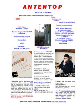
  • 1. ANTENTOP 01 2007 # 009 ANTENTOP is FREE e-magazine devoted to ANTENna’s Theory, 1-2007 Operation, and Practice Edited by hams for hams In the Issue: Antennas Theory! Practical design of HF-VHF- UHF Antennas! Home brew Technique! Propagation! QRP! And More…. UR5WCA Antenna Thanks to our authors: Prof. Natalia K.Nikolova N. Filenko, UA9XBI Valeriy Prodanov, UR5WCA Simuhin Aleksandr, RA3ARN Alexey Kostyuk, EW1LN ex RB5VD V. Polyakov, RA3AAE Kluyihin Alexandr, RU3GA G4AYO And others….. EW1LN 433-MHz Quad EDITORIAL: Well, my friends, new ANTENTOP – 01 -2007 come in! ANTENTOP is just authors’ opinions in the world of amateur radio. I do not correct and re-edit yours articles, the articles are printed “as are”. A little note, I am not a native English, so, of course, there are some sentence and grammatical mistakes there… Please, be indulgent! ANTENTOP 01 –2007 contains antenna articles, and several historical articles. Hope, it will be interesting for you. Our pages are opened for all amateurs, so, you are welcome always, both as a reader as a writer. Copyright: Here at ANTENTOP we just wanted to follow traditions of FREE flow of information in our great radio hobby around the world. A whole issue of ANTENTOP may be photocopied, printed, pasted onto websites. We don't want to control this process. It comes from all of us, and thus it belongs to all of us. This doesn't mean that there are no copyrights. There is! Any work is copyrighted by the author. All rights to a particular work are reserved by the author. 73! Igor Grigorov, VA3ZNW ex: RK3ZK, UA3-117-386, UA3ZNW, UA3ZNW/UA1N, UZ3ZK op: UK3ZAM, UK5LAP, EN1NWB, EN5QRP, EN100GM Contact us: Just email me or drop a letter. Mailing address: 209- 5879 Bathurst Str., Toronto, ON, M2R1Y7, CANADA Or mail to:antentop@antentop.org NB: Please, use only plain text and mark email subject as: igor_ant. I receive lots spam, so, I delete ALL unknown me messages without reading. ANTENTOP is FREE e-magazine, available FREE at http://www.antentop.org/
  • 2. ANTENTOP- 01- 2007, # 009 Editorial Welcome to ANTENTOP, FREE e - magazine! ANTENTOP is FREE e- magazine, made in PDF, devoted to antennas and amateur radio. Everyone may share his experience with others hams on the pages. Your opinions and articles are published without any changes, as I know, every your word has the mean. Every issue of ANTENTOP is going to have 100 pages and this one will be paste in whole on the site. Preview's files will be removed in this case. I do not know what a term for one issue will need, may be 8- 10 month or so. A whole issue of ANTENTOP hold nearly 10 MB. A little note, I am not a native English, so, of course, there are some sentence and grammatical mistakes there… Please, be indulgent! Preview: Some articles from "cooking" issue will be pasted for preview on this site, others no. Because, as I think, it must be something mysterious in every issue. Publishing: If you have something for share with your friends, and if you want to do it FREE, just send me an email. Also, if you want to offer for publishing any stuff from your website, you are welcome! Your opinion is important for me, so, contact if you want to say something! Copyright Note: Dear friends, please, note, I respect Copyright. Always, when I want to use some stuff for ANTENTOP, I ask owners about it. But… sometimes my efforts are failed. I have some very interesting stuff from closed websites, but I can not go to touch with their owners… as well as I have no response on some my emails from some owners. I have a big collection of pictures, I have got the pictures and stuff in others ways, from FREE websites, from commercial CDs, intended for FREE using, and so on... I use to the pictures (and seldom, some stuff from closed websites) in ANTENTOP. If the owners still are alive, please, contact with me, I immediately remove any Copyright stuff, or, if it is necessary, all needed references will be made there. I do not know, why the owners do not response me. Are they still alive? Do their companies are a bankrupt? Or do they move anywhere? Where they are in the end? Business Advertising: ANTENTOP is not a commercial magazine. Authors and I (Igor Grigorov, the editor of the magazine) do not get any profit from the issue. But off course, I do not mention from commercial ads in ANTENTOP. It allows me to do the magazine in most great way, allows me to pay some money for authors to compensate their hard work. I have lots interesting stuff in Russian, and owners of the stuff agree to publish the stuff in ANTENTOP… but I have no enough time to translate the interesting stuff in English, however I may pay money to translators, and, they will do this work, and we will see lots interesting articles there. So, if you want to put a commercial advertisement in ANTENTOP, please contact with me. A commercial advertisement will do ANTENTOP even greater interesting and various! I hope, readers do not mention against such commercial ads. Book Advertising: I do not think, that Book Advertising is a commercial advertisement. So, Book Advertising is FREE at ANTENTOP. Contact with me for details. Email: antentop@antentop.org subject: igor_ant NB: Please, use only plain text and mark email subject as: igor_ant. I receive lots spam and viruses, so, I delete ALL unknown me messages without reading. 73! Igor Grigorov, VA3ZNW ex: UA3-117-386, UA3ZNW, UA3ZNW/UA1N, UZ3ZK, RK3ZK op: UK3ZAM, UK5LAP,EN1NWB, EN5QRP, EN100GM http://www.antentop.org/ Editorial
  • 3. ANTENTOP- 01- 2007, # 009 Table of Contents Table of Contents Antenna Theory Page 1 Polarization and Related Antenna Parameters : by: Prof. Natalia K. Nikolova Dear friends, I would like to give to you an interesting and reliable antenna theory. Hours searching in the web gave me lots theoretical information about antennas. Really, at first I did not know what information to chose for ANTENTOP. Now I want to present to you one more very interesting Lecture - it is Polarization and Related Antenna Parameters Polarization of EM fields - revision. Polarization vector. Antenna polarization. Polarization loss factor and polarization efficiency. 5- 21 HF- Antenna Practice 2 BA- Butterfly Antenna : by: N. Filenko, UA9XBI The antenna is a version of a shunt fed loop (Reference 1). However, the antenna has some advantage compare to its prototype 22- 26 3 UR5WCA Balcony Antenna for 7, 10 and 14 MHz: by: Valeriy Prodanov, UR5WCA As I am an urban resident I have not a sufficient place for my antenna. My balcony placed at 2- floor at 5- store building is my sole antenna polygon. So, I have done a balcony antenna for my favorite 7, 10 and 14 MHz- ranges. It is a helical vertical that can be matched for these bands. 27- 29 4 Circle Antenna: By Simuhin Aleksandr, RA3ARN How is it happened that I did the antenna? Propagation on the 10 meter band pushed me to do the antenna. Propagation was coming, but I had not any antenna at my cottage. I really need an antenna. I have red at a text book that antenna having shape like a circle has a good characteristics. So, I decided to do a "Circle Antenna" and went to a local Home - Repair store for stuff for the antenna 30 5 Receiving Antennas Mystery of the Broom Antenna : by: V. T. Polaykov, RA3AAE, Ph. D in technical science Well known in Russia broom antenna has some mysterious property. What is the property- the puzzle try to solve Vladimir Polaykov. 31- 38 Page 1 http://www.antentop.org/
  • 4. ANTENTOP- 01- 2007, # 009 Table of Contents Table of Contents Page 6 UHF Antennas J-Pole Antenna for 433 MHz : Design by Alexey Kostyuk, EW1LN Just Design of J- Pole Antenna for 433 MHz 39 7 Antenna 'Triplet Quad' for 433 MHz: Design by Alexey Kostyuk, EW1LN Just Design of Triplet Quad for 433 MHz 40-41 8 VHF Antennas 144-MHz Antenna for Satellite Communication : by: ex RB5VD The simple antenna was tested at satellite communication. Signals from an amateur satellite (when the satellite was in visible sphere) were fine. Also the antenna worked well at local and DX QSOs. 42 9 SIMPLE KEYS Simple Iambic Key on PIC16F628A: by Kluyihin Alexandr, RU3GA Just very simple Iambic Key made with PIC16F628A 43- 45 TRANSCEIVERS 10 11 Tube - Semiconductor Transceiver (TST) : by: va3znw Transceiver TST was published in my book- "QRP Transceivers and PAs from Accessible Parts " The book was published by me (on my own expenses) in 1991, in Belgorod, Russia. I had printed 2000 samples of the book. The book describes kits which my own company ("Vibrissa") produced at the times. Fist such kit was transceiver TST. Were produced 400 kits of TST (Tube- Semi- conductor- Transceiver) near 50 of them were assembled by me for customers. Of course, may be some design of the transceiver seems to be old for the days, but what I can say, the transceiver works, and works not bad. RECEIVERS Simple SWL HF- VHF Receiver: From the book "DX Reception" (by Igor Grigorov (RK3ZK), Belgorod, 1994), pp.:76- 81. Using only 4 cheap surplus transistors and 1 mixer SBL- 1 you can do a HF- VHF receiver that provides good reception on HF (12- 29- MHz) and ex- Soviet BC FM VHF- 61- 88 MHz. Receiver catches AM and FM with deviation more the 25 kHz. Such receiver allows very quickly to find a propagation on the spectrum of HF and VHF bands. 46- 57 58-63 Page 2 http://www.antentop.org/
  • 5. ANTENTOP- 01- 2007, # 009 Table of Contents Table of Contents Page 12 PROPAGATION Long Delay Echoes LDE… Several articles on LDE were published at Antentop (use google search engine to find all articles at the site). Evidence of different people from different countries shows that LDE is not a myth, LDE is the reality. Subject "LDE" at www.qrz.com was appeared at hot summer 2007. Lots interesting commentaries were at the topic. Some of the replies (thanks for courteously permission of the authors) were pasted here. Next ball to reality of the LDE 64- 67 13 Time Warp Article Radio Signals out of Our Times was published at Antentop 01- 2006 as well as at www.cqham.ru. Below I paste only the feedback on the article from www.cqham.ru. Also I paste a feedback received by me on my email. You see, another hams also have met something like Time Warp in the Air…. 68-70 14 QRP Homebrewer Key for K1 : by: va3znw Just photos and schematic of an easy- build home- made key.... 71 15 Free e- book "QRP Transceivers and PAs from Accessible Parts ": by Igor Grigorov, UA3ZNW (*pdf), 28 pages. Book in Russian. The book was published by me (on my own expenses) in 1991, in Belgorod, Russia. I had printed 2000 samples of the book. Of course, it was not best paper used for the book as well as not good quality of printing. The book describes kits which my own company ("Vibrissa") produced at the times. Naturally, the book was the manual for the kits. Were produced 400 kits of TST (Tube- Semi- conductor- Transceiver) near 50 of them were assembled by me for customers, 200 kits SQT (Semi- conductor- Quartz- Transceiver), near 30 were of them were assembled by me for customers, 200 kits of PA, near 60 were of them were assembled by me for customers. Of course, the book will be interesting for all amateurs, not only for QRP- funs. Book weights 6,2 MB, so, it may take time to download. Below you can see the Contents of the book and path to download. 72 Page 3 http://www.antentop.org/
  • 6. ANTENTOP- 01- 2007, # 009 Table of Contents Table of Contents Page 16 DX Reception.: by Igor Grigorov, RK3ZK Book in Russian "DX Reception" was published by me in 1994, in Belgorod, Russia. It was printed (for my own expenses) 2000 samples of the 96- pages book. Only 1 of them I have in my stock for now. A long time I have been a fan of DX- SW radio reception. Till now I with great enjoy listen SW radio. It is really fan for me. The book contains description of antennas, some useful circuits, advices for DX- reception. All the antennas and circuits were proved by me. Book weights 13,3 Mb, so, it may take time to download. Of course, the book will be interesting for all amateurs, not only for fan of DX- SW Radio.. Below you can see the Contents of the book and path to download. 73- 74 17 HISTORY RAEM/mm Is My Callsign: by Ernst Krenkel, RAEM. (Translated in English by G4AYO The last voyage of E.T. Krenkel - a voyage to the Antarctic Circle, took place in 1968. He headed a voyage of the scientific-research vessel Professor Zubov, which was bound for the shores of Antarctica to relieve its staff of winterers found there, and also for oceanographic research. Below we publish extracts from the diary of E.T. Krenkel, which he kept during the voyage on the Zubov. He was a gifted narrator, graphic, with apt language in which were no trite sentences or clumsy wording. Ernst Teodorovich appears before us as a very ordinary man who with boyish ardour is concerned with his daily watch on the air for radio amateurs. 75- 79 18 Application for HF- VHF radio amateur station History goes away out of us… We lost in time papers, things and may be something else. That is why AntenTop published some old papers, old schematics, old photos. At this stuff you can see a copy of an application for a radio-amateur station. This application was used from 1965 till 1995 in the USSR, then in Russia. Below you can see thetranslation of the application and the scan of an original paper. 80- 82 19 20 Old Equipment Russian Receiver R- 311 Just brief description, photos and schematic diagram. Russian Receiver R- 326 Just brief description, photos and schematic diagram. 83- 84 85-88 Page 4 http://www.antentop.org/
  • 7. ANTENTOP- 01- 2007, # 009 Table of Contents Table of Contents Page 21 Useful Data TV Channels and Frequencies Just List of frequencies/Channels used by NTSC TV 89 22 FM Radio Channels and Frequencies Just List of frequencies/Channels used by FM Radio 90 23 One Coil Loop: Igor Grigorov, RK3ZK Hams often use One Turn Loop in their homebrewing. Such Loop may be used in a transmitting/receiving HF- VHF Magnetic Loop Antenna , in a simple VHF oscillator working on transmitting without antenna , in receiving VHF antenna for simple VHF receiver. 91- 92 24 Inductor Data It is easy to find the inductance of an inductor using equation shown on Figure 1. However, very often ham use for implementation of the inductor some normalized forms. So, it is possible to do tables that are contained data for such forms. Just tables with inductance data. 93- 96 25 Lightning Tank Calculator Very often an amateur need calculate parameters of resonator tank (see Figure ). Certainly, there are lots programs that can do the calculations. However very quick and with acceptable tolerance amateur can do it using given here Table. 97 26 Capacitor Code Just Number, Letter and Color Capacitor Code 98-99 27 Inductor Color Code Just Inductor Color Code 100 Page 101 http://www.antentop.org/
  • 8. ANTENTOP- 01- 2007, # 009 Polarization and Related Antenna Parameters Feel Yourself a Student! Dear friends, I would like to give to you an interesting and reliable antenna theory. Hours searching in the web gave me lots theoretical information about antennas. Really, at first I did not know what information to chose for ANTENTOP. Finally, I stopped on lectures “Modern Antennas in Wireless Telecommunications” written by Prof. Natalia K. Nikolova from McMaster University, Hamilton, Canada. You ask me: Why? Well, I have read many textbooks on Antennas, both, as in Russian as in English. So, I have the possibility to compare different textbook, and I think, that the lectures give knowledge in antenna field in great way. Here first lecture “Introduction into Antenna Study” is here. Next issues of ANTENTOP will contain some other lectures. So, feel yourself a student! Go to Antenna Studies! I.G. My Friends, the above placed Intro was given at ANTENTOP- 01- 2003 to Antennas Lectures. Now I know, that the Lecture is one of popular topics of ANTENTOP. Every Antenna Lecture was downloaded more than 1000 times! Now I want to present to you one more very interesting Lecture - it is a Lecture Polarization and Related Antenna Parameters. I believe, you cannot find such info anywhere for free! Very interesting and very useful info for every ham, for every radio- engineer. So, feel yourself a student! Go to Antenna Studies! I.G. McMaster University Hall Prof. Natalia K. Nikolova Polarization and Related Antenna Parameters Polarization of EM fields – revision. Polarization vector. Antenna polarization. Polarization loss factor and polarization efficiency. by Prof. Natalia K. Nikolova www.antentop.org mirror: www.antentop.boom.ru Page-5
  • 9. 6 The polarization is the figure traced by the extremity of the time- varying field vector at a given point. Lecture 5: Polarization and Related Antenna Parameters (Polarization of EM fields – revision. Polarization vector. Antenna polarization. Polarization loss factor and polarization efficiency.) 1. Polarization of EM fields. The polarization of the EM field describes the time variations of the field vectors at a given point. In other words, it describes the way the direction and magnitude the field vectors (usually E ) change in time. According to the shape of the trace, three types of polarization exist for harmonic fields: linear, circular and elliptical: x y z E x y z E ω x y z E Any type of polarization can be represented by two orthogonal linear polarizations, ( ,x yE E ) or ( ,H VE E ), whose fields are out of phase by an angle of Lδ . • If 0Lδ = or nπ , then a linear polarization results. • If /2 (90 )Lδ π= and x yE E= , then a circular polarization results. • In the most general case, elliptical polarization is defined. (a) linear polarization (b) circular polarization (c) elliptical polarization
  • 10. 7 It is also true that any type of polarization can be represented by a right-hand circular and a left-hand circular polarizations ( ,L RE E ). We shall revise the above statements and definitions, while introducing the new concept of polarization vector. 2. Field polarization in terms of two orthogonal linearly polarized components. The polarization of any field can be represented by a suitable set of two orthogonal linearly polarized fields. Assume that locally a far field propagates along the z-axis, and the field vectors have only transverse components. Then, the set of two orthogonal linearly polarized fields along the x-axis and along the y-axis, is sufficient to represent any TEMz field. We shall use this arrangement to demonstrate the idea of polarization vector. The field (time-dependent vector or phasor vector) is decomposed into two orthogonal components: x y x ye e e E E E= + = + , (5.1) ( ) ( ) ˆcos ˆ ˆcos ˆL x x x x j y y L y y e E t z x E E x e E t z y E E e yδ ω β ω β δ = − = = − + = (5.2) At a fixed position (assume 0z = ), equation (5.1) can be written as: ˆ ˆ( ) cos cos( ) ˆ ˆ L x y L j x y e t x E t y E t E x E y E e δ ω ω δ= ⋅ + ⋅ + = ⋅ + ⋅ (5.3) Case 1: Linear polarization: , 0,1,2,L n nδ π= = ˆ ˆ( ) cos( ) cos( ) ˆ ˆ x y x y e t x E t y E t n E x E y E ω ω π= ⋅ + ⋅ ± = ⋅ ± ⋅ (5.4)
  • 11. 8 arctan y x E E τ = ± τ 2 0 L kδ π τ = > x y E xE yE (a) (2 1) 0 L kδ π τ = + < τ x y E xE yE (b) Case 2: Circular polarization: and , 0,1,2, 2 x y m LE E E n n π δ π= = = ± + = ˆ ˆ( ) cos( ) cos[ ( / 2 )] ˆ ˆ( ) x y m e t x E t y E t n E E x y j ω ω π π= ⋅ + ⋅ ± + = ± ⋅ (5.5)
  • 12. 9 x y 0tω = 4 t π ω = 2 t π ω = 3 4 t π ω = tω π= 5 4 t π ω = 3 2 t π ω = 7 4 t π ω = ˆ ˆ( ) 2 2 m L E E x jy n π δ π = + = + + z x y 0tω = 4 t π ω = 2 t π ω = 3 4 t π ω = tω π= 5 4 t π ω = 3 2 t π ω = 7 4 t π ω = ˆ ˆ( ) 2 2 m L E E x jy n π δ π = − = − − z If ( ˆ)z− is the direction of propagation: clockwise (CW) or right-hand polarization If ( ˆ)z− is the direction of propagation: counterclockwise (CCW) or left-hand polarization
  • 13. 10 A picture of the field vector (at a particular moment of time) along the direction of propagation (left-hand circularly polarized wave): zβ zβ
  • 14. 11 Case 3: Elliptical polarization The field vector at a given point traces an ellipse as a function of time. This is the most general type of polarization of time-harmonic fields, obtained for any phase difference δ and any ratio ( / )x yE E . Mathematically, the linear and the circular polarizations are special cases of the elliptical polarization. In practice, however, the term elliptical polarization is used to indicate polarizations other than linear or circular. ˆ ˆ( ) cos cos( ) ˆ ˆ L x y L j x y e t x E t y E t E x E y E e δ ω ω δ= ⋅ + ⋅ + = ⋅ + ⋅ (5.6) Show that the trace of the time-dependent vector is an ellipse: ( ) (cos cos sin sin )y y L Le t E t tω δ ω δ= ⋅ − ⋅ ( ) cos x x e t t E ω = and 2 ( ) sin 1 x x e t t E ω = − 22 2 ( ) ( )( ) ( ) sin 2 cosy yx x L L x x y y e t e te t e t E E E E δ δ= − + or 2 2 1 ( ) 2 ( ) ( )cos ( )Lx t x t y t y tδ= − + , (5.7) where: ( ) cos ( ) sin sin x x L L e t t x t E ω δ δ = = ; ( ) cos( ) ( ) sin sin y L y L L e t t y t E ω δ δ δ + = = Equation (5.7) is the parametric equation of an ellipse centered in the x y− plane. It describes the motion of a point of coordinates ( )xe t and ( )ye t along an ellipse with a frequency ω . The elliptical polarization can also be right-hand and left-hand polarization, depending on the relation between the direction of propagation and the direction of rotation.
  • 15. 12 ( )xe t ( )ye t major axis (2 OA) minoraxis(2OB) τ xE yE E ω The parameters of the polarization ellipse are given below. Their derivation is given in Appendix I. a) major axis (2 OA× ) 2 2 4 4 2 21 OA = 2 cos(2 ) 2 x y x y x y LE E E E E E δ+ + + + (5.8) b) minor axis (2 OB× ) 2 2 4 4 2 21 OB = 2 cos(2 ) 2 x y x y x y LE E E E E E δ+ − + + (5.9) c) tilt angle τ 2 2 21 arctan cos 2 x y L x y E E E E τ δ= − (5.10) d) axial ratio major axis OA minor axis OB AR = = (5.11) Note: The linear and circular polarizations can be considered as special cases of the elliptical polarization. • If 2 2 L n π δ π= ± + and x yE E= , then OA OB x yE E= = = ; the ellipse becomes a circle.
  • 16. 13 The polarization vector is the normalized phasor of the electric field vector. It is a complex-number vector of unit magnitude and direction coinciding with the direction of the electric field vector. • If L nδ π= , then OB 0= and arctan x y E E τ = ± ; the ellipse collapses into a line. 3. Field polarization in terms of two circularly polarized components The representation of a complex vector field in terms of circularly polarized components is somewhat less easy to perceive but it is actually more useful in the calculation of the polarization ellipse parameters. ˆ ˆ ˆ ˆ( ) ( )R LE E x jy E x jy= + + − (5.12) Assuming a relative phase difference of C L Rδ ϕ ϕ= − , one can write (5.12) as: ˆ ˆ ˆ ˆ( ) ( )Cj R LE E x jy E e x jyδ = + + − (5.13) The relation between the linear-component and the circular-component representations of the field polarization is easily found as: ˆ ˆ( ) ( ) x y R L R L E E E x E E y j E E= + + − (5.14) 4. Polarization vector and polarization ratio 2 2 ˆ ˆ ˆ ,Ly jx L m x y m m m EEE x y e E E E E E E δ ρ = = ⋅ + ⋅ = + (5.15) The polarization vector takes the following forms in some special cases: Case 1: Linear polarization 2 2 ˆ ˆ ˆ ,yx L m x y m m EE x y E E E E E ρ = ⋅ ± ⋅ = + (5.16) Case 2: Circular polarization
  • 17. 14 The polarization ratio is the ratio of the phasors of the two orthogonal polarization components. It is a complex number. ( ) 1 ˆ ˆ ˆ , 2 2 2 L m x yx y j E E Eρ = ± ⋅ = ⋅ = ⋅ (5.17) or L L j y y V L L L x x H E E e E r r e r E E E δ δ = = = = (5.18) Point of interest: In the case of circular polarization, the polarization ratio is defined as: Cj R C C L E r r e E δ = = (5.19) The circular polarization ratio Cr is of particular interest since the axial ratio of the polarization ellipse AR can be expressed as: 1 1 C C r AR r + = − (5.20) Besides, its tilt angle is: 2 Cδ τ = (5.21) Comparing (5.10) and (5.21) readily shows the relation between the phase difference of the circular-polarization representation and the linear polarization ratio Lj L Lr r e δ = : 2 2 arctan cos 1 L C L L r r δ δ= − (5.22) One can calculate Cr from the linear polarization ratio Lr making use of (5.11) and (5.20): 2 4 2 2 4 2 1 1 2 cos(2 )1 1 1 1 2 cos(2 ) L L L LC C L L L L r r rr r r r r δ δ + + + ++ = − + − + + (5.23)
  • 18. 15 Using (5.22) and (5.23) allows easy switching between the representation of the wave polarization in terms of linear and circular components. 5. Antenna polarization The polarization of a radiated wave (polarization of a radiating antenna) at a specific point in the far zone is the polarization of the locally plane wave. The polarization of a received wave (polarization of a receiving antenna) is the polarization of a plane wave, incident from a given direction, and having given power flux density, which results in maximum available power at the antenna terminals. 6. Polarization loss factor and polarization efficiency Generally, the polarization of the receiving antenna is not the same as the polarization of the incident wave. This is called polarization mismatch. The polarization loss factor (PLF) characterizes the loss of EM power because of polarization mismatch. 2 ˆ ˆPLF | |i aρ ρ= ⋅ (5.24) The above definition is based on the representation of the incident field and the antenna polarization by their polarization vectors. If the incident field is ˆi i m iE E ρ= , then the field of the same magnitude that would produce maximum received power at the antenna terminals is ˆi a m aE E ρ= .
  • 19. 16 If the antenna is polarization matched, then PLF 1= , and there is no polarization power loss. If PLF 0= , then the antenna is incapable of receiving the signal. 0 PLF 1≤ ≤ (5.25) The polarization efficiency has the same physical meaning as the PLF. Examples Example 5.1. The electric field of a linearly polarized EM wave is ˆ ( , )i j z mE x E x y e β− = ⋅ It is incident upon a linearly polarized antenna whose polarization is: ˆ ˆ( ) ( , , )aE x y E r θ ϕ= + ⋅ Find the PLF.
  • 20. 17 2 [dB] 10 1 1 ˆ ˆ ˆPLF | ( ) | 22 PLF 10log 0.5 3 x x y= ⋅ + = = = − Example 5.2. A transmitting antenna produces a far-zone field, which is right-circularly polarized. This field impinges upon a receiving antenna, whose polarization (in transmitting mode) is also right-circular. Determine the PLF. Both antennas (the transmitting one and the receiving one) are right- circularly polarized in transmitting mode. Let’s assume that a transmitting antenna is located at the center of a spherical coordinate system. The far- zone field it would produce is described as: ( )ˆ ˆcos cos / 2far mE E t tθ ω ϕ ω π= ⋅ + ⋅ − It is a right-circularly polarized field with respect to the outward radial direction. Its polarization vector is: ˆ ˆ ˆ 2 jθ ϕ ρ − = According to the definitions in Section 4, this is exactly the polarization vector of a transmitting antenna.
  • 21. 18 x y z r ϕ θ Eθ Eϕ This same field far E is incident upon a receiving antenna, which has the polarization vector ˆ ˆ ˆ 2 a a a jθ ϕ ρ − = in its own coordinate system ( , , )a a ar θ ϕ . However, this field propagates along ar− in the ( , , )a a ar θ ϕ coordinate system, and, therefore, its polarization vector becomes: ˆ ˆ ˆ 2 a a i jθ ϕ ρ + = The PLF is calculated as: 2 2 ˆ ˆˆ ˆ| ( )( ) | ˆ ˆPLF | | 1 4 a a a a i a j jθ ϕ θ ϕ ρ ρ + − = ⋅ = = , [dB] 10PLF 10log 1 0= = There are no polarization losses.
  • 22. 19 Exercise: Show that an antenna of right-circular polarization (in transmitting mode) cannot receive left-circularly polarized incident wave (or a wave emitted by a left-circularly polarized antenna). Appendix I Find the tilt angle τ , the length of the major axis OA, and the length of the minor axis OB of the ellipse described by the equation: 22 2 ( ) ( )( ) ( ) sin 2 cosy yx x x x y y e t e te t e t E E E E δ δ= − + ( )xe t ( )ye t major axis (2 OA) minoraxis(2OB) τ xE yE E ω Equation (A-1) can be written as: 2 2 1a x b xy c y⋅ − ⋅ + ⋅ = , where: ( )xx e t= and ( )yy e t= are the coordinates of a point of the ellipse centered in the x y− plane; 2 2 1 sinx a E δ = ; 2 2cos sinx y b E E δ δ = ; (A-1) (A-2)
  • 23. 20 2 2 1 siny c E δ = . After dividing both sides of (A-2) by ( )xy , one obtains 1x y a b c y x xy − + = Introducing ( ) ( ) y x e ty x e t ξ = = , one obtains that 2 2 2 2 2 2 2 2 2 1 (1 ) ( ) (1 ) x c b a x y x c b a ξ ξ ξ ρ ξ ξ ξ ξ = − + + = + = + = − + Here, ρ is the distance of the ellipse point from the center of the coordinate system. We want to know at what ξ values the maximum and the minimum of ρ occur. This will produce the tilt angle τ . We also want to know what are the values of maxρ and minρ . Then, we have to solve 2 ( ) 0 d d ρ ξ = , or 2 2( ) 1 0 a c b ξ ξ − − − = (A-5) is better solved for the angle α , such that tan ; 2 y x π ξ α α τ= = = − Substituting (A-6) in (A-5) yields: 2 2sin sin 2 1 0 cos cos cos C α α α α α − − = × where 2 2 2 cos y x x y E Ea c C b E E δ −− = = . The solution of (A-7) is: (A-3) (A-4) (A-5) (A-6) (A-7)
  • 24. 21 1 2 12 2 1,2 1,2 2 cos1 arctan ; 2 2 x y x y E E E E δ π α α α τ α = = + − = Substituting 1α and 2α back in ρ yields the expressions for OA and OB. (A-8)
  • 25. ANTENTOP- 01- 2007, # 009 BA- Butterfly Antenna By: N. Filenko, UA9XBI ua9xbi@online.ru Credit Line: www.cqham.ru The antenna is a version of a shunt fed loop (Reference 1). However, the antenna has some advantage compare to a version from Reference 1. 1. Input impedance is closed to 50 Ohm. 2. The antenna has more narrow diagram directivity. 3. Easy to installation. It could be hanged between trees, trees and house, etc. Figure 1 shows the antenna at a horizontal installation. Figure 2 shows the diagram directivity of the antenna at its height 5 meters over real ground. Mostly vertical polarization is at the installation. Figure 3 shows the SWR the antenna at its height 5 meters over real ground. Figure 4 shows input impedance the antenna at its height 5 meters over real ground. The plots were taken with help of MMANA (Reference 2). UA9XBI Radio club ‘Arktika’ Championship 2004 Photo Credit Line: http://www.arktika.komi.com/Champ_2004.htm Figure 1 Butterfly Antenna at Horizontal Installation http://www.cqham.ru/ http://www.antentop.org/ Page 22
  • 26. ANTENTOP- 01- 2007, # 009 BA- Butterfly Antenna Figure 2 Diagram Directivity of the Antenna at Its Height 5 meters Over Real Ground Figure 3 SWR the Antenna Its Height 5 meters Over Real Ground http://www.antentop.org/ Page 23
  • 27. ANTENTOP- 01- 2007, # 009 BA- Butterfly Antenna Figure 4 Impedance of the Antenna at Its Height 5 meters Over Real Ground Antenna parameters at antenna horizontal installation are very depended on ground properties. The more wet ground the stronger main lobe is declined to the ground, I. e., the better antenna works for DX. Figure 5 shows the antenna at a vertical horizontal installation. Figure 5 Butterfly Antenna at Vertical Installation http://www.antentop.org/ Page 24
  • 28. ANTENTOP- 01- 2007, # 009 BA- Butterfly Antenna Figure 6 shows the diagram directivity of the antenna at its height 7 meters over real ground.Mostly horizontal polarization is at the installation. Figure 7 shows the SWR the antenna at its height 7 meters over real ground. Figure 8 shows input impedance the antenna at its height 7 meters over real ground. The plots were taken with help of MMANA (Reference 2). Figure 6 Diagram Directivity of the Antenna at Its Height 7 meters Over Real Ground Figure 7 SWR the Antenna Its Height 7 meters Over Real Ground http://www.antentop.org/ Page 25
  • 29. ANTENTOP- 01- 2007, # 009 BA- Butterfly Antenna Figure 8 Impedance of the Antenna at Its Height 7 meters Over Real Ground Antenna was made from bare copper wire in 4 mm diameter. May be used any 50 Ohm coax for feeding the antenna. Try place the coax athwart to antenna at least 5 meter. References: 1. Antennas for Radio Amateurs By Igor Grigorov, RK3ZK. Antentop -1-2007, Antentop 2- 2004 2. MMANA is free for Amateur Radio Use http://mmhamsoft.ham-radio.ch/ http://www.antentop.org/ Page 26
  • 30. ANTENTOP- 01- 2007, # 009 UR5WCA Balcony Antenna for 7, 10 and 14 By: Valeriy Prodanov, UR5WCA ur5wca@ukr.net Credit Line: www.cqham.ru As I am an urban resident I have not a sufficient place for my antenna. My balcony placed at 2- floor at 5- store building is my sole antenna polygon. So, I have done a balcony antenna for my favorite 7, 10 and 14 MHz- ranges. It is a helical vertical that can be matched for these bands. Figure 1 shows the view of the antenna. Figure 2 shows the schematic of the antenna. Design of the antenna: - Two verticals were made from PVC tube in 5 centimeters diameter. - On length of 1.35 meter of each tube were coiled 11.5 meters of insulated copper wire in 1- mm (18 AWG) diameter - Distance between the verticals is 1 meter At antenna clips an ATU (see References 1) was used with the antenna. Figure 3 shows the picture of the ATU. ATU (between coax and transceiver) is a must for the antenna. Figure 1 UR5WCA Balcony Antenna http://www.antentop.org/ Page 27
  • 31. ANTENTOP- 01- 2007, # 009 UR5WCA Balcony Antenna for 7, 10 and 14 SWR at 7, 10 and 14 MHz was near 1:1,1. While two weeks running the antenna on the bands I did a hundred CW QSO with practically of all the European countries and some district of Asia of the former USSR. I have received 569… 599. The antenna works with low SWR at 80- meters, however only local QSO was done. At 18 MHz the antenna has SWR 1:2. For testing the antenna I used a home- brew transceiver made on the base of old Russian receiver R-250 and ATU MFJ- 945E. Modification of the UR5WCA Balcony Antenna for 7, 10 and 14- MHz Figure 4 shows modification of the antenna that increases it performance. Inductors L1 and L2 were coiled by insulated copper wire in 1.5-mm (15- AWG) diameter, spacing between turns is 2-mm. Form diameter is 35- mm (was used PVC tape tubes), numbers of turns are 29, tap from 9 turn from cold end. FSM (Field Strength Meter) displayed increasing of electromagnetic field to 30% compare to antenna without matching coils. Figure 2 Schematic of the UR5WCA Balcony Antenna Figure 3 ATU of the UR5WCA Balcony Antenna http://www.antentop.org/ Page 28
  • 32. ANTENTOP- 01- 2007, # 009 UR5WCA Balcony Antenna for 7, 10 and 14 The measurement was made at distance 5 meter far the antenna. At antenna clips an ATU (see References 1) was used with the antenna. ATU (between coax and transceiver) is a must for the antenna. After numbers tests I did another modification. 1. Each vertical contains 20.2 meters of insulated copper wire in 1.5-mm (15- AWG) diameter. 2. The coils (see Figure 4) were deleted and verticals were connected straight away to pre ATU (see Figure 5). 3. A counterpoise (I used metal balcony hand-rail) was used with the antenna. After this modification noise level decreased, SWR was not changed. ATU (between coax and transceiver) is a must for the antenna. With the antenna I did some DX QSOs, for example, with KH0DQ (10-MHz, 589 to me) and 5Z4LS (14-MHz, 599 to me). Conclusion: Of course, it is only a surrogate antenna, but the antenna is worked, and works not bad. References: . http://www.qsl.net/gw6hmj/antenna.htm Figure 4 Modification of the UR5WCA Balcony Antenna Figure 5 ATU of the UR5WCA Balcony Antenna http://www.antentop.org/ Page 29
  • 33. ANTENTOP- 01- 2007, # 009 Circle Antenna By Simuhin Aleksandr, RA3ARN (ra3arn@mail.ru) How is it happened that I did the antenna? Propagation on the 10 meter band pushed me to do the antenna. Propagation was coming, but I had not any antenna at my cottage. I really need an antenna. I have red at a text book that antenna having shape like a circle has a good characteristics. So, I decided to do a “Circle Antenna” and went to a local Home - Repair store for stuff for the antenna I have found what I was looking for. I bought cheapest plastic tube for cold water, however, inside the plastic it was a metal tube in thick near 0.6 mm. I have bought 11 meters for 7 USD. Installation of the antenna was a very simple matter. I did the tube straight, in the center of the tube I did a hole, with help of a screw I attached the tube to the highest point of my wooden cottage. RA3ARN Then I shaped the tube in a circle, did several holes on the tube, with help screws did fastened the tube to the wooden wall of my cottage. That is all! Antenna is ready. An one- meter length of a 50- Ohms Coaxial Cable was attached between the antenna and ATU from an old military Russian radio R- 130M. With help the ATU I managed to get the SWR 1:1 at all amateur HF- bands, from 10 t0 160 meters. Lots interesting DX QSOs were made on the upper HF bands. I was surprised how the antenna was working on the 160 meter band. I had QSOs with almost all former region of the USSR at the 160 meters. Of course, the antenna is not perfect but it allowed me work well from my country cottage and had lots fun. 73 and DX! Simuhin Aleksandr, RA3ARN (ra3arn@mail.ru) http://www.antentop.org/ Page 30
  • 34. ANTENTOP- 01- 2007, # 009 Mystery of the Broom Antenna V. T. Polaykov, RA3AAE, Ph. D in technical science Well known in Russia broom antenna has some mysterious property. What is the property- the puzzle try to solve Vladimir Polaykov. 1. History of the Broom Antenna (BA) Broom Antenna has been well known in the USSR from old times. I have a Russian amateurs magazine from 1935 [1] with description of the antenna. “The antenna is made from a bunch of lengths of wires. There are used wires by 23 centimeters long. Narrow end of the bunch is inserted to an porcelain insulator. Wires in the bunch had angle in 15 degree from the center. A copper wire 15 meters long is going from the bunch to a receiver.” I cannot do scan for the figure from the magazine because its bad condition. However I pictured it possible to close to the original figure. Figure 1 shows the design of the broom antenna. The antenna was conveniently for the times because it needs only one mast for its installation. V. T. Polaykov, RA3AAE A witch usually used a Broom like a modern Jet http://www.antentop.org/ Page 31
  • 35. ANTENTOP- 01- 2007, # 009 Mystery of the Broom Antenna Sometimes the antenna was installed at a chimney, so no any mast was required. Up to our times the antenna is used for the radio reception (References [2, 3]). Figure 1 Design of the broom antenna (Note by I. G.: I had a book published at 1922 in Moscow where BA was described. However, at the book the antenna had a Reference back to 1916 year. It is a pity that I cannot take with me the old book in Canada. It is need to have a permission for any book older then 50 years to take the book abroad of Russia. It is not easy to obtain such permission, so lots old books were lived by me at Russia… Figure 01 shows a broom antenna from a book published at 1938 (original scan from book by A. P. Gorshkov “Handbook of Radio Amateur: Questions and Answers”, published in 1938 in Moscow) See also at horizontal antenna, competitor for the BA (Figure 02, original scan from the [01]. The horizontal antenna was mostly popular at the 30s.) At the magazine was written that an US company ‘Central Equipment Ltd’ produced the Broom Antenna. Wire going from the broom to a receiver was thoroughly insulated from walls with special insulators. Inside room the wire go through a special ebonite tube. It is pay attention the very careful isolation of the antenna wire from the nearest objects. A special grounding kit was included to the antenna. Figure 01 Broom antenna from a book published at 1938 Figure 02 Horizontal Antenna http://www.antentop.org/ Page 32
  • 36. ANTENTOP- 01- 2007, # 009 Mystery of the Broom Antenna Figure 03 (drawn by I.G. by Reference 1) shows the grounding installed in the soil. It was a copper tube with holes filled by so name “silitit” (Russian hams at such grounding used instead the “silitit” a charcoal). Bunch of copper wires went down the tube. So, the grounding looks like a Broom Antenna reversed by the wires bunch to the ground. At advertise of the company was wrote: “…. Above the advantages of easy in the installation the antenna has advantages in the reception”. Last phrase was puzzled me, what are the advantages? As usual BA antenna is considered as wire antennas with a capacitive load. Capacitive load made like a metal sheet was used by Hertz and Popov [02], capacitive loads made like several wires at the antenna end was used by Marconi [02], capacitive loads made like wire’s toroid was used by Tesla [02]. However, no one used a capacitive load made like a broom because it is not optimal implementation of this one. Circle (having dimension like a broom antenna) with several radial wires will have the same capacity like the broom antenna. Figure 2 shows a broom converted to an optimal capacitive load. At some description of the BA I found recommendation to use a strictly numbers of wires (19, 37 or 61 pieces) with length 50- 100 centimeters and use angle between center line and wires from 45 to 90 degree. Of course, it is nonsense. In theory 7 wires are enough for the antenna. BA made from 19- 37- 61 wires will have only a slightly more capacity compare to antenna made from 7 wires…. Figure 03 Grounding for Broom Antenna Installed in the Soil. http://www.antentop.org/ Page 33
  • 37. ANTENTOP- 01- 2007, # 009 Mystery of the Broom Antenna Figure 2 Broom converted to an optimal capacitive load So in the theory there is no any advantage of the broom antenna before another antenna with a capacitive load. However, a small metal ‘broom’ was used for discharging of some parts of electrostatic machines from 19 century. Recently the metal ‘broom’ are widely used at the end of antenna mast (that installed on the ground or on a ship), at the end of jet wings for leaking the static from the jet to the air. The ‘broom’ discharger looks like a Broom Antenna… So, what is can discharge the broom from the antenna? 2. Atmospheric electricity What are we know about an atmospheric electricity? Near the ground surface there is gradient of potential, i.e. strength of the electrostatic field is near 130 Volts/meter. At height of the human head the strength of the electrostatic field is near 200 Volts/meter. However we do not mention the potential because the air is very good insulator and current going through our body is too small. The more up the more potential will be. It is come due the follow effect. Upper layers of the Earth atmosphere are ionized (so called ionosphere) by the Sun rays. Ionosphere layer has some conductivity and charged positively (due some process) compare to the Ground surface. So, mankind lives between two plates of huge capacitor- one plate is the Ground another plate is the Ionosphere. However it is a small ionic current flow down to the Ground. It is very- very small current. The current density being measured by a high sensitivity device is several pico- Amperes per square meter. Scientists do not clear explain the phenomenon. One of hypothesis says that the current exists due lightning and thunderstorm [4]. Really, before a thunderstorm the current is increased dramatically and sometimes we could register the effect visually. It is the corona discharge – bright glowing at the end of high metal mast, sometimes the corona charge is going from trees, wooden or metal cross at the top of churches. Corona discharge is especially bright in the mountains and in the sea (where the air is especially clear). Such Corona Discharge had been well known from the very old times, it was called Saint Elmo's fire. Saint Elmo's fire Atmospheric electricity had been studied from 17- century [5]. Lots great scientists (in the US Benjamin Franklin [03] the inventor of the lightning rod, in Italy Giovanni Beccaria [04], in Russia- Mihail Lomonosov and Georg Rihman [05] ). Franklin studied the effect with help of a metal wire lifted with help of a kite in the sky. http://www.antentop.org/ Page 34
  • 38. ANTENTOP- 01- 2007, # 009 Mystery of the Broom Antenna Benjamin Franklin January 17, 1706 April 17, 1790 Giovanni Battista Beccaria 1716 - 1781 Another portrait of Benjamin Franklin Lomonosov and Rihman studied the atmospheric electricity with help of a high raised metal rod, Rihman was killed during the experiments by a lighting. Giovanni Beccaria such metal road firstly connected to the earth , then connected to electroscope and then observed the reaction of the device. So, he could measure the potential of the road compare to ground. Beccaria called the metal road and electroscope “meter of the good weather.” I tried to repeat Beccaria’s experiment. To my new installed 30- meter length antenna I connected an electroscope. While several minutes potential at the electroscope was raised to 1,500 Volts, then something clicked on my antenna (I believe some insulator sparked) and the electroscope was discharged. It happened periodically. Electroscope used by Franklin and Beccaria http://www.antentop.org/ Page 35
  • 39. ANTENTOP- 01- 2007, # 009 Mystery of the Broom Antenna However, through several weeks I could not catch static at the electroscope. It is obvious antenna insulators catch dirty from the Moscow air and could not keep high static voltage across itself. Mihail Lomonosov (1711—1765) 3. Current from the Air Broom Antenna connected to antenna terminal of old radio as usual has ground potential because almost any old radio has coupling inductor where one end is connected to antenna and other end is connected to the ground. BA is placed near 10-15 meters above the ground where the air has potential compare the ground near + 2,000 Volts. So, from wires of the broom a small ions current is flow. The more wires in the broom, the more current go in to antenna wire. The more space occupancy wires of the antenna the more current go in to the antenna. The more sharpener are ends of wire of the broom, the more current in the antenna. So, the current in the antenna direct depend from: 1. Numbers of the wire in the broom; 2. Angle between center line and wires; 3. Sharpener of the ends of the wire. Georg Rihman 1711- 1753 Rihman’s Electroscope A- Wooden Strip B- Flax Tread C- Scale http://www.antentop.org/ Page 36
  • 40. ANTENTOP- 01- 2007, # 009 Mystery of the Broom Antenna Lots of the all description of the Broom Antenna pointed that the efficiency of the antenna depends from the factors, factors that increase the atmospheric current in the antenna. But how increasing of the current can influence to the reception? I may suggest the follow hypothesis. Ion current flowing from the broom wires looks like short conductive path. Incoming radio signal may modulate the conductive path. So, atmospheric current going into antenna wire may be modulated by nearby radio signals. Antenna circuit is tuned to desired incoming radio signals, so only wanted radio signals would have maxima strength of the current… Another suggestion. Ion current flowing from the broom wires may create a column of ions above the antenna. The column may work like an additional antenna connected to the broom, so, it looks like our broom antenna physically making longer by the column of ions. I have read in one old book interesting note. Reception of DX stations coming better at winter windless evening when in the home began light the oven. When I read it I though it is nonsense. How an oven can improve radio reception? But for now I understood that it is not nonsense. Smoke from a chimney goes straight in the sky at windless weather. However the smoke column is a stream of easy- ionized air, so, the column has a little conductivity. Of course, such smoke antenna may improve performance of existing antenna or by re- radiation or adding its height to the existing antenna. BTW from I.G.: It is really that a Russian Oven may be treated (with some limitations) like an ion generator… Note by I.G.: At first it was strange to me. Why atmospheric current that flows in the antenna wire can improve the antenna performance? Another puzzle for me: in Russia Broom Antenna has another name – low noise antenna. Lots Russian amateurs handbooks described the antenna like low noise. For example, [06] described the antenna like low noise antenna for reception. I had used the antenna in 70s, I could speak that is really low noise antenna that gave good reception. However next chapters of the articles are cleared for me the puzzle. 4. Parameters of Silent and Corona discharge Lets examine volt/ current parameters of the broom antenna, i.e. how depends discharging current from potential between the air and antennas ends. If we will increase potential between the air and wires of the Broom Antenna the current that flow in the antenna also will increase. It is so called Silent Discharge that going because always there are some quantity of “free” ions in the air. Figure 3 shows Antenna Current Vs Potential between antenna wires and the air. Russian Oven- an Ion Generator? Low Noise Broom Antenna from [06] The further increasing of the potential between the air and broom wires result to dramatically increasing free ions near the wire the ions can do further ionization of the air near the broom wires and current in the antenna wire increase significant. http://www.antentop.org/ Page 37
  • 41. ANTENTOP- 01- 2007, # 009 Mystery of the Broom Antenna Figure 3 Antenna Current Vs Potential between antenna wires and the air Q-factor can be found as reactance of the circuit divided to resistance of losses. When the BA has negative resistance, the resistance compensates the resistance of losses in the antenna. Q-factor of the circuit is increased and RF voltage across the antenna circuit is risen. So, we have increasing in the receiving signals due feeding the antenna by atmospheric electricity. Certainly, there are lots interesting questions about work of the Broom Antenna. What amplification the antenna may provide? What is the power the antenna gives? Figure 4 Antenna Amplifier Note I. G.: The process about appearance the corona discharge is described above with some simplification. If you print in GOOGLE “corona discharge” and then related phrase, you find hundreds pages containing lots equation… But I leave it to real fun of the corona discharge. It is may appear wonderful, but at some conditions it is very possible to turn the broom antenna into field having the “negative resistance.” Proper height above the ground or proper conditions of the atmosphere may turn the antenna to field of the “negative resistance.” In the Figure 3 it is point Iopt. To keep the antenna in the field of so called “negative resistance” it is need to stabilize current into antenna wire. It is possible to do feeding the antenna through “source of current.” However, the atmosphere is an ideal “source of current.” So being turn to the field of the “negative resistance” antenna may stay at the conditions quite enough long time… 5. Antenna Amplifier Part of curve where potential drop but the current is risen is very interesting part of the curve. The part of the curve has so called “negative resistance.” Electronic device that has curve with such “negative resistance” may do amplification (of course at some condition). The devices are tunnel diode, neon bulb, thyratron, thyristor. Tunnel diode is used for amplification and generation at VHF- UHF bands. Neon bulb, thyratron, thyristor is used for generation up to hundreds kHz. Figure 4 shows the simplified schematic of Antenna Amplifier. In to antenna circuit is turn on the Broom Antenna. Current in the antenna circuit at resonance increases in Q times, where Q is Q-factor of the circuit. What is the lower and upper frequencies range of the Broom Antenna? Be truth, I do not know answer on the questions. The Broom Antenna required more research. I will be grateful for any additional information from those who made such researchers. References: 1. New Type of Reception Antenna. Radiofront, # 15, August 1935, page 50. 2. http://oldradio.onego.ru/ARTICLES/metelka.jpg 3. V. A. Nikitin Никитин. “100 and one antenna design”. Moscow, publishing house “Symbol-R”, 1996. 4. http: // www.cultinfo.ru/fulltext/1/001/008/080/ 253.htm 5. http: // www.ionization.ru/issue/iss63.htm 6. V. Polyakov.: Physics of aeroionization. Radio, 2002, # 3, pp.: 36-38. 01. V. V. Vnyutin.: Detector Receivers.: Moscow, 1950 02.http://www.antentop.org/marconi.htm http://www.antentop.org/fessenden.htm http://www.antentop.org/003/tesla.htm 03 http://en.wikipedia.org/wiki/Benjamin_Franklin 04. http://www.newadvent.org/cathen/16009a.htm 05. http://www.peoples.ru/science/founder/lomonosov/ http://fiz.1september.ru/2003/32/no32_1.htm 06. Handbook of Radio Amateur: F. Burdejnyj, N. Kazanskiy, A. Kamalyagin, K. Shulgin. Moscow, publishing house DOSAAF, 1953 73! http://www.antentop.org/ Page 38
  • 42. ANTENTOP- 01- 2007, # 009 J-Pole for 433 MHz Design by Alexey Kostyuk, EW1LN EW1LN J- Pole for 433-MHz. May be made from copper or aluminum stuff. MMANA file is located at http://www.qsl.net/ew1ln/3j58.html. Sizes in centimeters. ● - ● – feeding points. Credit Line: EW1LN, http://www.qsl.net/ew1ln/ 73! http://www.antentop.org/ Page 39
  • 43. ANTENTOP- 01- 2007, # 009 Antenna ‘Triplet Quad’ for 433 MHz Design by Alexey Kostyuk, EW1LN Triplet QUAD Antenna for 433-MHz. May be made from copper or aluminum stuff. MMANA file is located at http://www.qsl.net/ew1ln/3elq.html. Credit Line: EW1LN, http://www.qsl.net/ew1ln/ http://www.qsl.net/ew1ln/ http://www.antentop.org/ Page 40
  • 44. ANTENTOP- 01- 2007, # 009 Antenna ‘Triplet Quad’ for 433 MHz http://www.antentop.org/ Page 41
  • 45. ANTENTOP- 01- 2007, # 009 144-MHz Antenna for Satellite Communication By ex RB5VD Credit Line: http://www.cqham.ru/an_144s.htm Figure 1 Design 144-MHz Antenna for Amateur Satellite The simple antenna was tested at satellite communication. Signals from an amateur satellite (when the satellite was in visible sphere) were fine. Also the antenna worked well at local and DX QSOs. The antenna made from copper tap tubes. Upper horizontal parts may be made from a tube or from a thick bare ware. Figure 1 shows the design of the antenna. Input impedance of the antenna is 75 Ohm. At 70- 80s some Russian commercial and military VHF transmitters had such output impedance. To change antenna impedance to 50 Ohm just connect coaxial cable a little down from the feedpoint. DD of the antenna is circle in horizontal and eight- shape in vertical plane. www.cqham.ru http://www.antentop.org/ Page 42
  • 46. ANTENTOP- 01- 2007, # 009 Simple Iambic Key on PIC16F628A Credit Line: http://ru3ga.qrz.ru/ Kluyihin Alexandr, RU3GA ra3ggi@mail.ru This simple key is assembled with a PIC16F628A. Internal controller’s generator on 4-MHz provides function of the PIC. The key can work at feeding voltage from 2 to 5.5-V. Some samples of the PIC16F628A may work when feeding voltage drop ever to 1.2-V. Consumption current at working mode is 2- 4-mA (at supply voltage 5-V) and 0.5- 0.8-mA (at supply voltage 3-V). Consumption current at sleeping mode is less the 1-µA. So, the key can be fed from a small Lithium battery which may be fed the key (ever without a Power Switch) for several years. Specification Iambic mode with memory of last item of data Iambic manipulator may be reversed with help of buttons 4 memory cells, each one has capacity of 30 letters Memory cell can be written by PIC’s key. Rewriting resource is 1,000.000 times. Needed corrections in the entering data may be made during the record Data in the memory cell keep saved without power supply across the PIC Keying speed could be adjusted (with help of a variable resistor) from 4-WPM up to 100-WPM. Sidetone is 800-Hz Sidetone can turn ON/OFF with buttons Simple hand key may be switched on Ratio “dot- gap- dash’ may be chosen with a multipoint switch: a) 0.75-1.25-3 b) 1-1-3 c) 1-1-3.5 d) 1-1-4 e) 1-1-4.5 Operation ● Record to a memory cell Hold button of needed memory cell for 2 seconds. Speaker transmits “WR” – it means that key stands for the record. At a record the gap between letters the key recognizes automatically. For installation a gap between words you need to do pause in the record for 2 seconds. Speaker transmits “R” – it means that the key is “understood” the gap between words and key is waiting for the record of next data. So, before enter of new data you may drink a coffee or read a book. Key will wait you for the record. When only 3 letters are to finish the memory cell the Sidetone is changed in frequency. To terminate the record tap any button. ● Correction of Data If an erroneous symbol was entered do transmitting dots in number more than six. Speaker will transmit “R”- it means that key stands in “Correction Mode.” After that speaker transmit “Last” + “last right letter” and go to Waiting Mode. Speaker transmits “Last NO” if an error was on the first record letter. PCB for the Key by DL3MIH http://www.antentop.org/ Page 43
  • 47. ANTENTOP- 01- 2007, # 009 Simple Iambic Key on PIC16F628A http://ru3ga.qrz.ru/ http://www.antentop.org/ Page 44
  • 48. ANTENTOP- 01- 2007, # 009 Simple Iambic Key on PIC16F628A Example: Should be necessary to record “CQ DE RU3GA.” However it was recorded “CQ DI.” To fix the error we transmit series of dots, Speaker transmits “R,” then “Last D,” after that key turns to a Waiting Mode, enter “E RU3GA,” tap any button, that is all. However, it is possible correct any letter. See example below. Example: Should be necessary to record “CQ DE RU3GA.” However, it was entered “CQ NI.” To fix the error we transmit series of dots, Speaker transmits “R,” then “Last N,” after that key turns to a Waiting Mode, again we transmit series of dots, Speaker transmits “R,” then “Last Q,” after that key turns to a Waiting Mode…. Enter “DE RU3GA” then tap any button. ● Play Data from a Memory Cell Tap a button of the appropriate Memory Cell ● Stop Play Data from a Memory Cell Click by any paddle of the Iambic manipulator or tap a hand key ● Sidetone OFF/ON 1. Push and hold Button 1, then push Button 2, Hold both Button while 4 seconds. Speaker transmits “OFF’- Sidetone is Off. 2.To turn Sidetone On repeat 1. The option is recorded in memory. After OFF/ON key would stay in mode that was before Off. ●Tune Mode Push and hold Button 1, then push Button 3, Hold both Button while 4 seconds. Go off from Tune Mode- tap any button or click by manipulator. ● Reverse Iambic Paddle 1. Push and hold Button 1, then push Button 4, Hold both Button while 4 seconds. Speaker transmits “REV’- manipulators paddle for “Dot” and “Dash” will be reversed. The option is recorded in memory. After OFF/ON key would stay in mode that was before Off. Design Depends on your needs the key may be built up in a transceiver or used as a separate project. Sidetone’s Out may be switched on the transceiver speaker. Switch for interval “Dot- gap- Dash’ may not be installed. In this case you are reached the ratio “1-1-3.” However, R1-R3 must be installed. The key was tested me, however, some errors and glitch in the program are possible. So, you feedback are welcome! Mail to: ra3ggi@mail.ru Last Hex may be loaded (September 6, 2007): http://ru3ga.qrz.ru/UZLY/key.shtml 73! From RU3GA SHACK + WORKBENCH RU3GA http://www.antentop.org/ Page 45
  • 49. ANTENTOP- 01- 2007, # 009 Tube – Semiconductor Transceiver (TST) Transceiver TST was published in my book- “QRP Transceivers and PAs from Accessible Parts “ The book was published by me (on my own expenses) in 1991, in Belgorod, Russia. I had printed 2000 samples of the book. The book describes kits which my own company (“Vibrissa”) produced at the times. Fist such kit was transceiver TST. Were produced 400 kits of TST (Tube- Semi- conductor- Transceiver) near 50 of them were assembled by me for customers. Of course, may be some design of the transceiver seems to be old for the days, but what I can say, the transceiver works, and works not bad. 72/73! I.G. Transceiver TST Tube- Semiconductor- Transceiver (TST) The transceiver consists of from two parts: there are RX part and ТХ part. Let’s see how it is worked beginning from the TX part. TX Figure 1 shows the circuit of the tube’s part of the transceiver TST. VFO made on tube V1 (grid- cathode part). Zener diode VD1 (100V/ 20mA) provides the stable voltage to the tube. V1 works not only as VFO. L2C5 (switched in anode circuit) doubles the VFO frequency that depends on L1C2. Driver is assembled on V2, PA made on V3. In my case the VFO worked very stable when Russian tube 6J2P was used in it. However, at 160- 20 meters pentode 6J1P works not bad. Inductor L1 is coiled on Russian resistor MLT-2 or WS-2 (it is depends on used band). The coil is uniformly spread on the form. The inductor should be coiled by wire that provides coiling turn to turn. To provide stability of the VFO the inductor coiled on the form firstly coated with neutral glue. I used Russian glue BF-2. Wire of the inductor is coiled (above the glue) with a small tension. After coiling the glued inductor is dried at + 150 C- degree while 2 hours. After that the inductor one more time is coated with the glue. After that the inductor is dried at room temperature for 24 hours. Remember, from the quality of the L1 depends the frequency stability of the TST. I had reached at 10- meters band the drift 200 HZ/hour with my home made inductors (and proper C2,C3). Of course, if you managed use a ready- made inductor from an old VFO- use it. Tap to cathode goes from ¼ from the “cold end.” (At my kit a special ceramic form for L1 was included) If you can not get good air- dielectric Cn for the VFO - use a variable resistor that is switched on as the Figure 2 shows. Resistor may have whole resistance in 1… 3-k. Tap to the resistor is taken from middle of the inductor. C* (27- 100-pF) is required picking to desire frequency range. The schematic provides less stability compare to air- variable capacitor. However, it is very possible to get a good stability just picking the capacitors (around L1) having different Temperature Coefficient of Capacity. Figure 2 Variable Resistor instead Variable Capacitor Adjusting and Tuning VFO At first tune the tank L1C2 (with help a receiver or digital frequency meter) to needed frequency. Do not forget that the circuit is tuned to ½ or 1/3 frequency from used one. Then tune receiver to used frequency and tune L2C5 to maximum strength of the signal. Of course, you may use an RF voltmeter to do it. Then tune L3C8. http://www.antentop.org/ Page 45
  • 50. ANTENTOP- 01- 2007, # 009 Tube – Semiconductor Transceiver (TST) http://www.antentop.org/ Page 46
  • 51. ANTENTOP- 01- 2007, # 009 Tube – Semiconductor Transceiver (TST) It is possible to do in two different ways. First, use a receiver and tune to maximum strength. Second, turn on an amperemeter between R4 and C18 and tune to minimum current. Current at resonance L3C8 fall but voltage across resistor R7 (it is measured by a high- ohms voltmeter, preferably electromechanical (not digital) is raised. Note: V3 at the measurement the voltage across R7 should be in the socket, heater turn on but the voltage from anode and grid- 2 should be removed. After the final tuning L3C8 turn on anode voltage to V3, turn on an antenna to X1, and tune the PA (with help of C15, C16) to maximum power going in to the antenna. LED VD1 shows the power, the brighter it glows the more power is going in to the antenna. Coupling loop L5 should be placed at proper distance at L4, LED should not glow too bright that may cause fault for this one. As usual the circuit (L4,C15,C16) is being tuned at the center of an amateur band does not require to be retuning to the edges of the band. So, if only one antenna (or several antennas having the same input impedance, for example 50 Ohms) is used, it is possible use fixed capacitors C15, C16. At the PA a Russian tube 6P3S, 6P6S, 6P14P, 6P9, 6P15P works well. First three work well at 160 through 20 meters, the last two work well at 20- 10 meters. Table 1 shows data for all inductors of the TX. Table 1 Data for inductors of the TX * First column- numbers of turns, second column- length of winding. Otherwise inductor is winded uniformly on to the form. ** Inductor L4 is coiled on a form in diameter 34 millimeter. For 160- 80 meters use wire 0.8 mm (20 AWG), for 40- 20 meters use wire in 1.0 mm (18 AWG), for 17- 10 meters use wire 1.0… 2.0 mm (18- 12 AWG). diameter 0.1- 0.2 mm (37- 32 AWG), for 40- 30 meters may be wound by wire in 0.25- 0.5 mm (30- 24 AWG), for 20- 10 meters may be wound by wire in diameter 0.5- 0.8 mm (24- 20 AWG). *** L1, L2, L3 are coiled on Russian resistors WS2 or MLT-2. Resistance for these ones should be more then100-k for L1 and L2. For inductor L3 the resistance should be more the 27-k. L1 for 160- 80 meters may be wound by wire in Note: Capacitors C1 and C5 may need be chosen to your implementation of the L1 and L2. Use a variable capacitor with a big marked limb to determinate the value of C1 and C5. Then install a fixed capacitor instead the variable. http://www.antentop.org/ Page 47
  • 52. ANTENTOP- 01- 2007, # 009 Tube – Semiconductor Transceiver (TST) L2 for 160- 80 meters may be wound by wire in diameter 0.1- 0.2 mm (37- 32 AWG), for 40- 30 meters may be wound by wire in diameter 0.25- 0.5 mm (30- 24 AWG), for 20- 10 meters may be wound by wire in diameter 0. 5- 0.8 mm (24- 20 AWG) L3 for 160- 80 meters may be wound by wire in diameter 0.1- 0.2 mm (37- 32 AWG), for 40- 30 meters may be wound by wire in diameter 0.25- 0.5 mm (30- 24 AWG), for 20- 10 meters may be wound by wire in diameter 0.5- 0.8 mm (24- 20 AWG) When TX is assembled and tuned, it is possible try to do QSOs using this one and separate receiver. At this case increase the capacity of the shift – frequency capacitor C1 to 100… 300-pF.It makes the shift of the VFO frequency far away from the amateur band. Solder the C1 to another end of the S1.1 (compare to shown in Figure 1) to shift the frequency in the low edge of the frequency band. Note: Do not stay V3 at high voltage when the VFO or/and driver does not work properly. V3 gets the grid bias voltage from detecting an RF by the part- “1-grid- cathode.” Without bias voltage (the same without an RF on the first grid) the tube may overheated (due huge anode current) and goe off operation. After tuning TX tune the RX part. Part List TX Tubes: V1: Russian Tube 6J2P- small RF Pentode with short characteristic V2: Russian Tube 6J1P- small RF Pentode with short characteristic V3: Russian Tube 6P15P- RF Power Pentode Resistors: R1: 39 k/ 0.25 W* (27- 100 k) R2: 3.3 k/ 0.5 W* (680 Ω – 5.6 k) R3: 15 k/ 2 W* (12 – 18 k) R4: 18 k/ 2 W* (12- 24 k) R5: 3.3 k/ 0.5 W* ((680 Ω – 5.6 k) R6: 39 k/ 0.25 W* (27- 68 k) R7: 39 k/ 0.25 W* (27- 51 k) R8: 5.6 k / 1 W* (3.3- 6.8 k) *Recommended () In brackets- may be used Capacitors: C1: 2… 10 pF* C2: See Table 1 C3:100 pF** C4: 0.022 uF*** C5: See Table 1 C6: 0.022 uF*** C7: 100 pF** C8: See Table 1 C9: 0.022 uF*** C10: 0.01 uF*** C11: 0.01 uF*** C12: 0.01 uF*** C13: 0.01 uF*** C14: See Table 1 C15: See Table 1 C16: See Table 1 C17: 27 pF** C18: 0.022 uF *** C19: 100 pF** Cn: 10- 50 pF**** * Depend on frequency shift ** Tolerance +100- 30% *** Tolerance +200- 30 % **** Depend on used band Diodes VD1: Zener Diode, 100 V/20 mA, should be placed on a small heater sink, I had used a coin having dimension of a 25 cents US coin. VD2: Any small power RF diode VD3: Any LED VD4: Any small power RF diode VD5: Any small power RF diode Switches: S1: Any DPDT switch that can be used at 250 V/ 100 mA Connectors: X1: Any RF Connector X2: 5- PIN Audio Connector http://www.antentop.org/ Page 48
  • 53. ANTENTOP- 01- 2007, # 009 Tube – Semiconductor Transceiver (TST) RF- Choke: RFC1: Wound on Russian Resistor WS-2 (sizes: diameter 9.7-mm, length 49-mm), resistance more than 51-k. Figure 3 shows the RFC implemented for different bands. Figure 3. RFC for TST A) 180- 80 meters: 50+60+70+80+80 turns by insulated wire 0.1-mm (38-AWG); B) 40- 30 meters: 3 section wound turn to turn by insulated wire 0.2- mm (32- AWG); C) 20- 10 meters: 1 section is wound with step 0.3 – mm, second section wound turn to turn by insulated wire 0.2-mm (32-AWG). RХ A DC receiver is used at the TST. Figure 4 shows schematic of the receiver. Figure 4. Circuit diagram for DC receiver of the TST RF Amplifier: It has active component T1 and T2. VD1… VD4 are protected the input RF Amplifier from an overload by own transmitter or power signals coming from the Air. The diodes allow use for the transceiver a separately antenna (sometimes it allows to avoid AC hum in the head phones). Adjusting the RF Amplifier is simple. With help of R3 install at emitter of T2 half voltage compare to collector T2. Check current of T2. It should be 5- 10-mA. If the current is higher – increase R1 then check again voltage at emitter T2. If the current is lower, decrease the R1, then again check voltage at emitter T2. L1C1 and L2C5 should be tuned on working frequency. Driver for VFO: It is made on T3. Check drain current when signal from VFO is applied to the gate of the T3. It should be not more then 15-mA. If the current is more, play with R5 and C6. It is useful to play with R5 and C6 on to best reception. RF Amplifier and Driver for low- bands: At 160- 40 meters you may use simplified RF amplifier made on 1 transistor and driver made on usual bipolar transistor. However, at such design the AC hum may come to head- phones.It may come difficulties with adjusting the driver to obtain an optimal RF voltage at mixer. Frequency between TX and RX may drift. Figure 5 shows the schematic for simplified RF Amplifier (A) and Driver (B). Quasi- Balanced Mixer: It is made on diodes VD5… VD9. RF is coming through L2.2 to the mixer. R6, R7 and C7, C8 provide quasi - balancing. No tuning and adjusting at right parts. Audio Filter: It is made on C9, R8 and C10. Cutting frequency is near 3.5-kHz. If you have a commercial made Audio Filter (for example, from an old TRX) – use it. Turn on this one instead R8, C10 may be deleted. It is possible turn on instead R8 an old Universal Magnetic Head (from an old tape recorder), however, in some case an AC hum may come. No tuning and adjusting at right parts. http://www.antentop.org/ Page 49
  • 54. ANTENTOP- 01- 2007, # 009 Tube – Semiconductor Transceiver (TST) http://www.antentop.org/ Page 50
  • 55. ANTENTOP- 01- 2007, # 009 Tube – Semiconductor Transceiver (TST) Figure 5 Circuit diagram for simplified RF Amplifier (A) and Driver (B) Audio Amplifier: It is made on T4, T5, T6, T7. It is preferable to use a low noise high – gain transistors. It may be any low power old- made germanium or modern silicon transistors. Adjusting is a very easy. With help of R9 install at collector T4 the voltage 4.5-V. With help of R21 install at collector T4 the voltage 6.0-V. If audio amplifier has self-excitation, increase R11 (for example to 6.8-k or more). Bridge Wien: Bridge Wien (detailed shown on Figure 6) does rejection of the 50-Hz. The frequency is used at AC in Europe. It is possible re- count (using equation from the Figure 6) both as rejection frequency as parts for the bridge. Parts should have as possible small tolerance as can. Figure 6 Bridge Wien It is possible to use a precision potentiometer instead R3 (on Figure 6) to adjust the rejection frequency. Figure 7 shows PCB (from side of the foil). PCB has sizes 100 x 70 mm. Figure 8 shows view to montage of the RX. Board made by through- hole montage. Figure 7 PCB of the RX http://www.antentop.org/ Page 51
  • 56. ANTENTOP- 01- 2007, # 009 Tube – Semiconductor Transceiver (TST) Figure 8 Montage of the RX (Arrow shows to “Phones”) Part List RX Resistors: R1: 300/0.25 W* R2: 39 k/ 0.25 W* R3: 39k/ 0.25 W* R4: 220 /0.25 W* (200- 1000 Ω) R5: 39k/0.25 W* R6: 360/0.25 W* (470- 1000 Ω) R7: 360/ 0.25 W* (470- 1000 Ω) R8: 2.2k/0.25 W* (1k- 3.9k) R9: 100k/0.25 W* R10: 10k/0.25 W* (5.6k- 10k) R11: 3.9k/0.25 W* R12: 8.2k/ 0.25 W* (5.1k- 10k) R13: 1k/0.25 W* R14: 150k/0.25 W** R15: 150k/0.25 W** R16: 150k/0.25 W** R17: 150k/0.25 W** R18:220k/0.25 W* (39k- 300k) R19: 39k/0.25 W*(27k- 51k) R21: 10k/0.25 W* (8.2k- 12k) R22: 3.9k/0.25 W* (3.9k- 6.8k) *Recommended ** Tolerance 2% () In brackets- may be used R6 must be similar to R7 Capacitors: C1: See Table 2 C2: 0.01 uF* C3: 0.01 uF* C4: 68 pF C5: See Table 2 C6: 68 pF C7: See Table 2 C8: See Table 2 C9: 0.5 uF C10: 0.1 uF C11: 5.0 uF** C12: 5.0 uF** C13: 0.022 uF*** C14: 0.022 uF*** C15: 0.022 uF*** C16: 0.022 uF*** C17: 0.022 uF*** C18: 0.1 uF * C19: 3300 pF* C20: 50.0 uFf** C21: 0.1 uF * C22: 1.0 uF * * Tolerance +200- 30% ** Electrolytic *** Tolerance 5% C7 must be similar to C8 Diodes VD1- VD10: Any small power RF diodes VD5- VD8 must be similar Connectors: X1: 5- PIN Audio Connector RF- Choke: RFC1: Wound bulky by insulated wire 0.1-mm (38- AWG) on Russian Resistor WS- 0.5 (sizes: diameter 5.5-mm, length 26-mm), resistance more than 51-k. For quantity of turns see Table 2. http://www.antentop.org/ Page 52
  • 57. ANTENTOP- 01- 2007, # 009 Tube – Semiconductor Transceiver (TST) Semiconductors VT1: Small power N- channel RF FET VT2: Small power NPN bipolar RF transistor VT3: Small power N- channel RF FET VT4: Low noise high- gain PNP audio transistor VT5: Low noise high- gain PNP audio transistor VT6: Low noise high- gain PNP audio transistor VT7: Low noise high- gain PNP audio transistor Table 2. Data for inductors for the receiver * Inductors for 160- 80 meters is wound bulky by insulated wire 0.1-mm (38-AWG) on Russian Resistor MLT- 2 (sizes: diameter 8.6-mm, length 18.5-mm), resistance more than 51-k. For others bands (40- 10 meters) the inductors are wound uniformly by insulated wire 0. 5-mm (25-AWG) on Russian Resistor MLT- 1 (sizes: diameter 6.6-mm, length 13-mm), resistance more than 51-k. ** C7 and C8 may have tolerance -60 +100%, however, C7 must be similar to C8 *** RFC1: Wound bulky by insulated wire 0.1-mm (38- AWG) on Russian Resistor WS- 0.5 (sizes: diameter 5.5-mm, length 26-mm), resistance more than 51-k. Figure 3. RFC for TST Note: Capacitors C1 and C5 may need be chosen to your implementation of the L1 and L2. Use a variable capacitor with big marked limb to determinate the value of C1 and C5. Then install a fixed capacitor instead the variable. Design TST Experience shows that design in DC transceiver plays the same role as the schematic does. Perform the transceiver strictly to the draft and you obtain good result. Figure 9 shows design of the TST. Figure 9 Design of the TST http://www.antentop.org/ Page 53
  • 58. ANTENTOP- 01- 2007, # 009 Tube – Semiconductor Transceiver (TST) According to Figure 9: 1. Connector + 250/+12/ AC 6.3V 2. Key 3. Ventilating holes 4. Stipes (may be made from a cap of toothpaste) 5. Toggle - Switch TX-RX 6. Tuning Dial, made from a PCB stuff 7. Tuning Knob (may be made from a cap from a plastic can), glued by “Crazy Glue” to item 6 8. Wide Strap (made from transparent Plexiglas) 9. Support Pole 10. LED ТХ 11. Tuning РА Figure 10 shows the view upside to the montage of the TST. Montage must be done strictly to the figure. Figure 11 shows view to inside of the TST. Drafts with sizes (in millimeter) for items 1- 11 are shown below. Leads of the TX’s parts are soldered to pad (the pad dimension on 4x4 mm are cutting on the PCB at parts position). L4 made from a heavy wire (for 20- 10 meters) may be just soldered by its leads to X1 and C15. L4 for 160- 30 meters wound on a form (plastic or cardboard) may be fastened to item 8. Holes intended the Tube Plastic Socket have sizes a bit less the sockets. So the sockets are hard inserted to the holes then grounding leads soldered to PCB. Figure 10. View upside to the montage of the TST http://www.antentop.org/ Page 54
  • 59. ANTENTOP- 01- 2007, # 009 Tube – Semiconductor Transceiver (TST) Figure 11. View inside of the TST Steps to assembling TST: 1. Have done ready items 1- 11 (do not forget that item 6 made from a double- sided PCB) 2. Have checked that all holes are made and made correctly 3. Install tubes’ sockets 4. Solder edges at items 1- 9 5. Do fastened in several points item 1,2,7,9 Items 3- 4 http://www.antentop.org/ Page 55
  • 60. ANTENTOP- 01- 2007, # 009 Tube – Semiconductor Transceiver (TST) 6. Do fastened in several points item 3,6,8 7. Do final soldering the (paragraph 5@6) items 8. Do montage TX 9. Tune the VFO to needed frequency range, then install item 4. VFO frequency may go down for a little. 10. Install a working board RX 11. Install item 5, do calibration of the transceiver 12. Install cover 10 and 11. Cover 11 is installed up the transceiver, cover 10 (consists from 2 parts) down the transceiver. Item 10a closes VFO, item 10b closes PA. It is possible to do item 1, 9 10 and 11 a little bigger (shown in dashed line at Figure 9). In this case all sides of the transceiver will be closed. Transceiver will be work more stable at 20- 10 meters. Item 6, 9 Item 2 http://www.antentop.org/ Page 56
  • 61. ANTENTOP- 01- 2007, # 009 Tube – Semiconductor Transceiver (TST) Item 7 Item 1, 10, 11 http://www.antentop.org/ Page 57
  • 62. ANTENTOP- 01- 2007, # 009 Simple SWL HF- VHF Receiver From the book “DX Reception” (by Igor Grigorov (RK3ZK), Belgorod, 1994), pp.:76- 81. (Article published with inessential cutting) See ANTENTOP- 01- 2007, p.p.: 73- 74. Using only 4 cheap surplus transistors and 1 mixer SBL- 1 you can do a HF- VHF receiver that provides good reception on HF (12- 29- MHz) and ex- Soviet BC FM VHF- 61- 88 MHz. Receiver catches AM and FM with deviation more the 25 kHz. Such receiver allows very quickly to find a propagation on the spectrum of HF and VHF bands. The chart of the receiver is shown on Figure 1. Receiver includes balanced mixer (1), low-pass filter (2), high-pass filter (3), VFO that works at 16- 33 MHz (4), superregenerative detector aka IF amplifier on 45 MHz (6). Switched filters are formed a working band of the receiver (HF or VHF). The receiver has two struck points. First lays on 22. 5 MHz the second one is on 65.5 MHz. If you want to have reception on the frequencies just move the IF of the receiver (with help of C11) up or down. Figure 1. Chart of the simple SWL receiver Note: The figure is original scan from the “DX Reception” book. English commentary are given inside oval. The simplicity of design of the receiver and its high sensitivity (just at connection of an antenna in 1 meter length the receiver provides satisfactory reception on the HF and VHF bands) is reached by a superregenerative detector. However the superregenerative detector gives basic lacks of the receiver – low selectivity and low dynamic range. There is no SSB reception. Figure 2 shows the circuit diagram for low-pass (Fig. 2a) and high-pass (Fig. 2b) filters. The filters were made for 50 (75) input/ 50 (75) Ohms output, i.e., the filters require a 50 (75) Ohms antenna and mixer having 50 (75) Ohms input. SBL-1 is okey for that. However the receiver works well with an antenna having almost any input impedance. Figure 3 shows the circuit diagram for the receiver. If you have no SBL- 1 you may do the mixer according to Figure 3. Figure 2. Circuit diagram for low-pass (Fig. 2a) and high-pass (Fig. 2b) filters (Values for all capacitors are given in picofarads) Note: The figure is original scan from the “DX Reception” book. English commentary are given inside oval. Figure 3. Circuit diagram for simple SWL receiver Note: The figure is original scan from the “DX Reception” book. English commentary are given inside oval. Table 1 shows data for inductors of the receiver and filters. All coils are wounded by insulated copper wire in diameter 1-mm (18 -AWG), all coils are air- wounded. The filters are assembled in a box (80X40X40- mm) soldered from two- sided PCB. The receiver is assembled in a box (155x 90x 55- mm), soldered from two- sided PCB. Figure 4 shows component layout for the receiver. The components are sitting on the wiring strips from an old tube receiver. When the receiver will be tuned close the box, where the receiver is assembled, by a plate of a PCB. The plate should be soldered at several places to the box. Figure 4 Components layout for simple SWL receiver Design and Tuning Low-pass and high-pass filter made strictly to Table 1 and Figure 4 does not require any tuning. VFO made from good parts according to the schematic works straight away. Only the tuning is the set up of the frequencies range. Needed frequencies range do rough by the pressing- stretching of the L9, fine with the C2. Arrange L10 near L9 to maxima and equal across the band sensitivity. http://www.antentop.org/ Page 58
  • 63. ANTENTOP- 01- 2007, # 009 Simple SWL HF- VHF Receiver http://www.antentop.org/ Page 59
  • 64. ANTENTOP- 01- 2007, # 009 Simple SWL HF- VHF Receiver http://www.antentop.org/ Page 60
  • 65. ANTENTOP- 01- 2007, # 009 Simple SWL HF- VHF Receiver http://www.antentop.org/ Page 61
  • 66. ANTENTOP- 01- 2007, # 009 Simple SWL HF- VHF Receiver Table 1. Data for inductors # Inductor Diameter of the Inductor, mm Length of winding, mm Quantity of Coils Note L1 14 10 8 Athwart to L2, L3 L2, L3 14 20 7 L4 14 5 4 L5 14 10 7 Athwart to L6, L7, L8 L6 14 20 11 L7 14 20 14 L8 14 10 6 L9 18 25 7.5 L10 18 4 2 Near “cold” end L9 L11, L12 18 14 8 Tap from 2 Turn from “cold” end Superregenerative stage adjusted with R11 and C10. When superregenerative stage is working properly you hear specific noise in the speaker. Frequency of the stage (IF) set up with help of C11. After that do tuning L12C15 to maxima sensitivity of the receiver. Audio Amplifier made from good parts according to the schematic works straight away. Almost any low power, low noise (better high- gain) transistors work well at the receiver. Transformer TP3 was used from an old transistor radio. Was used a 16 Ohms Speaker from an old transistor radio. It is possible (ever better) switch on a high- impedance head phone instead the TP3. Parts List Resistors: R1: 1 k R2 100 k R3: 15 k R4: 10 k R5: 100 k R6: 120 Ohm R7: 1.2 k R8: 8.2 k R9: 5.1 k R10: 10 k R11: 100 k , potentiometer R12: 8.2 k R10: 10 k R11: 100 k , potentiometer R12: 8.2 k K = multiply to 1000 Ohm All resistors 0.125 W Capacitors: C1: Variable, air dielectric, 10- 100 pF C2: Variable, air dielectric, 2- 15 pF C3: 22 pF C4: 560 pF C5: 0.05 uF C6: 6800 pF C7: 3300 pF C8: 3300 pF http://www.antentop.org/ Page 62
  • 67. ANTENTOP- 01- 2007, # 009 Simple SWL HF- VHF Receiver C9: 0.05 uF C10: Variable, air dielectric, 2- 15 pF C11: Variable, air dielectric, 2- 15 pF C12: 1.5 pF C13: 4700 pF C14: 3300 pF C15: Variable, air dielectric, 2- 15 pF C16: 5.0 uF/ 10V C17: 5.0 uF/ 10V C18: 20.0 uF/ 12V Polarized capacitors are electrolytic Diodes: VD1… VD4: Any small low power RF Shottky diodes VD5: Zener diode 9.0V/15 mA Transformers: TP1, TP2: Core: Amidon analog is T37- 10 10 turns by trifilar insulated wire OD 0.15 mm (34 AWG), winding to 1 cm length. Uniformly onto the core. So, primaly winding 1- 10 turns, secondary winding 2- 10 third winding 3- 10 turns. ● – winding phase TP3: Audio transformer from an old transistor radio Note: Diodes VD1- VD4 and transformers TP1 and TP2 may be changed to IC SBL-1. Transistors: VT1: Small power RF germanium transistor, gain 80- 100, upper frequency 250 MHz May be changed to silicon transistor with equal data. VT2: Small power RF germanium transistor, gain 80- 100, upper frequency 250 MHz May be changed to silicon transistor with equal data. VT3, VT4: Any high gain (100- 200) small power transistors Switch: S1: Any Toggle DPDT RF Choke RFC: OD: 3.5… 5 (not critical)mm Length of winding: 15… 20 (not critical)mm Coiled by insulated wire OD 0.15 mm (34 AWG) Winding: Turn to turn, uniformly 73! I.G. From forum QRP- ARCI (QRP- F- Forum) Posted by: John AE5X, Posted On: 07/15/07, Subject: Russian woodpecker antenna From UA0AAM here is the antenna used at one of the radar sites that we copy on the ham bands at times. I'd sure love to have this baby on 40m some winter evening. I wonder if it's rotatable...? http://www.antentop.org/ Page 63
  • 68. ANTENTOP- 01- 2007, # 009 Long Delay Echoes www.qrz.com LDE… Several articles on LDE were published at Antentop (use google search engine to find all articles at the site). Evidence of different people from different countries shows that LDE is not a myth, LDE is the reality. Subject “LDE” at www.qrz.com was appeared at hot summer 2007. Lots interesting commentaries were at the topic. Some of the replies (thanks for courteously permission of the authors) were pasted here. Next ball to reality of the LDE W5HTW Posted: July 09 2007,08:21 I also experienced an LDE while working for the US government, in the mid 1960s. It was on CW. It was only a portion of a regular one-minute long transmission we made, automatically, on a guard frequency. Our guard sent one minute of CW then one minute of monitoring. We monitored simultaneously four different HF frequencies, on speaker monitor, as we were often away from the operating console. Following one of the one-minute transmissions, a few seconds after it stopped, part of that transmission was repeated back, but since I was not at the console I do not know on which receiver it was heard. At the time we were monitoring frequencies at 6, 10, 13, and 18 mhz. My guess would be the 13 mhz frequency, but it is only a guess. The duration of the echo was only about 10-12 seconds, not a complete retransmission. It had no fade. It was on frequency, so was not shifted by any Doppler. http://www.antentop.org/ Page 64
  • 69. ANTENTOP- 01- 2007, # 009 Long Delay Echoes It was our signal, same speed, same automatic keying characteristics, same everything. We had a tape of it for a long time, and I had a copy of the tape, but at some point, years ago, I lost it or erased it. LDEs are real. It appears the most logical solution is some sort of ducting, the signal returning to earth in a moving path, which accounts for it being heard only briefly at the originating site. Ed Ed wrote an interesting article on LDE that is at his website : http://w5htw.home.att.net/index.html. With Ed’s kindly permission the article is printed below. ------------------------------------------------------------------ LDES - LONG DELAYED ECHOS There are stories told in the cult books of radio signals being heard again years after the radio station left the air. One such story involved a broadcast AM station that had closed down, yet the radio signal was heard nearly two years after the station went off the air. Those stories are like the UFO and ghost stories. They have no foundation. LEDs, though, are very real. What they are not, are attempts by some alien space craft to contact us. What they are is an as-yet unexplained electromagnetic phenomena relating to radio waves. In the 1960s Stanford University's Physics Lab tried to find an explanation for them but LDEs have no apparent useful purpose, so allocating much in the way of scientific time or funds is pretty unlikely. The study closed with only a few suggestions. There are some facts available about the standard LDE. First, it does not show signs of Doppler shift. It is on frequency, it remains on frequency for the duration, and the pitch, if it is CW, remains steady. Secondly, it is rarely a full transmission. It is segments, often very short segments, only five or six seconds, of a transmission. It may not begin at the beginning, and it may not end at the ending of the original transmission. It is not complete. Third it does not fade in or fade out. It is "there." At least that is true of the one I heard that was so clearly identifiable. It turns on, and then it turns off. Fourth, they have been showing up LONG before computer sound cards. While it is possible one or two could be a hoax, it is highly unlikely. Fifth, they are not limited to the ham bands. Sixth, reports of them are mostly in the 3 to 18 mhz range. Occasionally one is heard above that, and on very rare occasions, one below that. This could be because most radio activity is in that range, so it really isn't a defining fact, but it is a point to consider. MY OWN EXPERIENCE To my knowledge I have heard only one LDE. It is possible I have heard others, but did not recognize them as such, perhaps due to crowded band conditions, or other situations. The one I heard, though, was unmistakable. To explain it, I have to set the scene a bit. This was in 1967, in the Far East. I was a government radio operator/tech at a somewhat isolated radio relay site. We ran a CW net that was used almost entirely for the purpose of establishing contact and setup procedures for RTTY operations. Hence it carried very little, and very intermittent, CW traffic. We ran three or four transmitters simultaneously, depending upon time of day. We ran four receivers (Collins 51J3/R388) models in a console. There was a J38 straight key for our use. There was also a Frederick Electronics Baudot to Morse converter, that converted 5-level punched paper (or plastic) TTY tape to Morse. We ran what is typically know as a "guard" frequency. You've heard them on the marine bands. It sends something like: VVV VVV VVV DE KGP444 KGP444 KGP444 QSX 4/6/10 K And then there is silence. That is the listening period. Our machine sent this (and this is a fictitious call sign, not the one we used) VVV VVV VVV DE AAA123 AAA123 AAA123 VVV VVV VVV DE AAA123 AAA123 AAA123 VVV VVV VVV DE AAA123 AAA123 AAA123 QSX 4/6/10 K (In the day time the freqs would change to 6/10/13) That sequence, at 18 wpm, took just about one full minute. The tape then looped (using "letters" characters) for another full minute, during which time any station could call in. www.qrz.com http://www.antentop.org/ Page 65
  • 70. ANTENTOP- 01- 2007, # 009 Long Delay Echoes Because our transmitters were located a couple of miles away, we ran the receivers at full RF gain all of the time. There was NO muting! All four receivers were wired to a speaker panel. That meant any signal heard would be heard throughout the building. Twice each hour, on the hour and on the half hour, one of us (there were usually only two on duty) would actually sit down at the receivers for "close monitor." For that, we switched the speakers to a panel down near the desktop, and we would sit for two minutes and monitor. At all other times, the operator was away from the position and doing other things, so he had to be able to hear the R388s above all the Teletype noise in the building - and we had a LOT of such noise! Motors for printers and machines, plus air conditioning, fans, and the like. So the receivers were very loud. When our transmitters keyed, the AGC action of the receivers served to mute them, as we kept the AGC slow. The first "beep" of the CW shut down the AGC, which prevented any full breakin. There was no other muting. Just pretty much receiver overload! Now the scene is set. It is not close monitor time, and I, with my partner, am doing other work in the RTTY section. We grow accustomed to hearing the receivers go dead as our own transmitters overload them. Then the background noise returns. Suddenly we hear: VV DE AAA123 AAA123 AAA123 VVV Then it's gone. It lasted perhaps five or six seconds. It did not fade in, it did not fade out. It "turned on' and then it "turned off." It was our keying. At our speed, and automatic. It was strong, but nowhere near strong enough to kick the AGC and overload the receivers. It was not strong enough to even "thump" them. It was simply a fairly strong CW signal. For an instant I thought it was someone calling us. Since that did not happen unless there was a problem, I moved quickly to the console. I stopped our automatic keying and I listened. No one on any of the frequencies. I sent "QRZ DE AAA123 K" with the hand key. Got no response. I tried that maybe three times. No one was out there. Of course I was keying all four transmitters simultaneously, so no matter what frequency he had called in on, I would hear him. Then it dawned on me! I had heard "DE AAA123!" He had been identifying as my station! Not AAA123 DE AAB321, for example. It was "DE ME!" By sheer luck, we had been running a slow speed monitor tape on another receiver in a different rack. That was a rack with two Collins 51S1 receivers, that we used to monitor other things, but it had been set up to monitor a couple of frequencies, and I had, earlier in the afternoon, set one of those two receivers on one of our guard frequencies. The other was on some other frequency. What if, I thought, the echo had been on that particular guard channel? I had no way of knowing which of the console receivers had picked up the signal but it was early evening, and we had been about to close down the 13 mhz guard, as it was no good for us at night, so it wasn't likely it would be there. I could be on our 4, 6 or 10 mhz frequencies, and there was no way of knowing. But the 51S1 was on the 6 meg guard frequency. What if! I ran the tape back. Yes, indeedy, it had been on the 6 mhz guard frequency. And I had a tape of it. Not only that, because because the four channel recorder used one of its channels to permanently monitor a highly accurate 1 KHZ oscillator, I could now tell precisely what time the signal had been recorded, using our test gear designed for that purpose. All that told me nothing. Except it was not one of our field stations. It was not our own transmitter being keyed by our keyer. It was a received signal, and in ham language would have been RST589. We gave it a QRK5, QSA5. The only thing I knew for sure about it now was it had been on our 6 MHZ frequency, not on the four or 10 mhz one. I made a copy of that segment of the tape, as it was something we wanted our technical staff to analyze for us. They did, and learned nothing more. I kept the tape for a few years but finally erased it. Shortly after the actual occurance, (perhaps a few months) which neither my coworker or I understood at the time, I happened across a story on LDEs. And then we knew what we had heard. Again I played the tape several times, but garnered no information from it. Except one thing. The "echo" had begun 16 seconds after the end of our transmission. But it had not begun at the beginning. It had not echo'ed our entire transmission, only a few seconds of it. All this took place outside the USA. www.antentop.org http://www.antentop.org/ Page 66
  • 71. ANTENTOP- 01- 2007, # 009 Long Delay Echoes Some things we did know. It was not ham operators. It was not a hoax. It was not foreign intelligence. It was not one of our own transmitters. It was not a recording. (thank about that one, and why you know it was not an audio recording!) It was not one of our field stations. It did not fade. It had no Doppler. It was our keying, at our speed. It was reasonably strong, but not enough to trigger AGC on the receiver. It was very clear, with no QRM. It was in the 6 MHZ band. I have never heard another one. I have some theories about LDEs, but I'm no scientist, so I just keep them to myself, mostly. I think the key, though, is the word 'ducting.' Have Fun. ----------------------------------------------------------------------- K8VPL Posted: July 10 2007,07:15 An LDE happened to me once, back around 1963, at a near sunspot minimum. About 3AM Eastern Time, I don't remember what season, I was trying to hear ANYTHING on 40 meter CW. The band was dead, and the noise level was very low. I had called several CQ's, and heard the last several letters of my call coming back about 3 to 4 seconds after I sent them. I tried a few "dits", and they came back just as I sent them. This went on for about 5 minutes. The returning echoes sounded like they had come a long way, all fluttery, and just above the noise level, but on the same exact frequency, and matching my fist exactly. I'll never forget what they sounded like. 73 Ted, K8VPL ---------------------------------------------------------------------- aa4w Posted: July 12 2007,19:12 I just wanted to add my experiences with LDE's. In the late 60's I spent quite a bit of time on aircraft carriers in the Mediterainean and we were running lots of phone patches. On numerous occasions I heard the last several words we had transmitted after we unkeyed the transmitter. At first I thought it was someone playing a prank but I soon realized it was our signals. The delays were longer during times when the propagation was best and as I remember I never heard them during daylight hours which figures in with the ionaspheric conditions. I agree it is an odd sensation the first few time you hear it. Rick AA4W ----------------------------------------------------------- n9kpn, Tim Posted: July 18 2007,15:37 I experienced LDE on 11M (CB SSB) back in the late 80's. A friend would be in town and drive to college some 50 miles away. He'd go mobile and I'd use my base station. The almost half way point, 27 miles, was where we would have to sign off. Sometimes we'd make it a little bit longer, but rarely too much farther. One evening as he is headed back to school as he got further apart, we kept hearing another station jump in. He'd hear one when I talked, I'd here one when he talked. But they would not reply when we addressed them. As he got further away we noted that we were hearing a delay of the original transmission! Once past the half way point we could hear each other from the delayed transmission. This was one of the only times we could hear each other the full 60 or so miles. Eventually the echo faded and we lost contact. 73! I.G. http://www.antentop.org/ Page 67
  • 72. ANTENTOP- 01- 2007, # 009 Time Warp Article Radio Signals out of Our Times was published at Antentop 01- 2006 as well as at www.cqham.ru. Below I paste only the feedback on the article from www.cqham.ru. Also I paste a feedback received by me on my email. You see, another hams also have met something like Time Warp in the Air…. July 26, 2006, Maxim, 4Z5PM: Already during several weeks every night in the time from 24.00Z till 02.00Z on CW segment of the 20 meters approximately each 40 minutes a propagation to South America is appeared. Duration of the propagation is from 2 to 8 minutes. Does someone observe a similar? August 27, 2006 at 02:07 UA1TAT: All these facts (at the article Time Warp) break not the laws of the Nature but only our current knowledge about the Nature. It would be very interesting to collect the facts and then to study them. I met with the strange phenomena of Time Warp. At November 1984, at 144,050 MHz, I had heard my own CQ that I sent 14 minutes ago. I was very surprised because at the times only few hams from my location used to the 2 meters and I was familiar with all of them. So a joke from somebody was impossible. www.cqham.ru http://www.antentop.org/ Page 68