We are offering a comprehensive high speed networking solution which is including 3.2T Co-packaged Optic (CPO), 100G, 200G, 400G & 800G transceivers, DACs, AOCs, ACCs & Loopback modules. We are fulfil your research (R&D) stage product development, DVT/EVT pre-product testing, mass production and also for final application use.
Welcome to contact us for more product info.
anritsu mp1800a Анализатор качества сигнала BERonlinestuden
Тест битовых ошибок BER
детектор ошибок до 10мВ;
измерения BER до 32х каналов;
Функции измерений для PON, усилителей EDFA
4PAM/8PAM генератор 32.4PAM BER;
OTN 10G, ODU Multiplexing, ODU Flex, STM-64 OC-192, FC 1G 2G 4G, FC 8G 10G; Отвечает современным требованиям операторов, внедряющих OTN, MPLS-TP, 10/100G, при этом поддерживая тестирование устоявшихся стандартов SDH/PDH, как встроенного в OTN, так и в отдельных каналах
Анализ ядра сети CORE, METRO. магистральных, регональных, пограничных узлов; тестирование городских сетей и сетей доступа.
Позволяет произвести оценку влияний микроскопических дефектов волокна на большом расстоянии от прибора, оценить влияние вибрации, с помощью автоматизации и программного обеспечения возможно получить подробную статистику, провести анализ изменения параметров кабеля в зависимости от времени, температуры, внешних влияний
Модуль Gigabit Ethernet mu909060a3 для MT9090Aonlinestuden
Тестер Gigabit Ethernet на базе Network Master специально предназначен для тестирования линий Ethernet в полевых условиях. Аппаратное обеспечение и пользовательский интерфейс оптимизированы для упрощения использования персоналом с любыми начальными навыками, а также для функционирования в жестких условиях.
Гигабитный тестер оптических каналов Anritsu mu909060a1 для MT9090Aonlinestuden
Возможность выбора трансиверов электрических RJ45 и оптических SFP для двух портов.
Реализация новой методики стандарта МСЭ-Т для тестирования сквозных соединений Ethernet. Методика по Y.1564, одновременное тестирование множества потоков трафика, эмулирующего реальную работу сети. Поддержка стекованного
VLAN (Q-in-Q), MPLS, IP версии 4 и 6
Оптический анализатор спектра mu909020a для Anritsu MT9090Aonlinestuden
Позволяет провести быстрый контроль мощности, длины волны, девиации на всех 18 каналах CWDM от 1250 до 1650 нм по МСЭ-Т G.694.2. Полоса пропускания покрывает все 18 CWDM каналов, в соответствии с ITU-T G.694.2. Ширина полосы пропускания ±6.5 нм, соответствует стандарту ITU-T G.695
Легкая но прочная конструкция весом менее 700гр, отсутствие слабых элементов, вентиляторов и герметичность гарантирует долгий срок службы в полевых условиях
Возможно подключение одного модуля к платформе Network Master, модуль быстро снимается и заменяется на другой. В зависимости от подключаемого модуля получаем нужный инструмент - рефлектометр, спектрометр
Оптический рефлектометр, универсальное решение, сокращающее время измерения при настройке и техобслуживании сетей FTTx, кабельного ТВ, LAN, сетей доступа и Metro-сетей
Это универсальное устройство имеет производительность и функции для оценки всех активных оптических компонентов, включая мо-дули SFP, XFP и SFP+, а также оптические трансиверы и оптические источники VCSEL и DFB. Результаты оценки, такие как центральная длина волны, уровень, спектр, SMSR, OSNR и др., отображаются на одном экране. Вместе с тестером коэффициента ошибок по битам (BERT) поддерживает анализ спектра выходных сигналов оптических трансиверов и сигналов WDM
This presentation, created by Syed Faiz ul Hassan, explores the profound influence of media on public perception and behavior. It delves into the evolution of media from oral traditions to modern digital and social media platforms. Key topics include the role of media in information propagation, socialization, crisis awareness, globalization, and education. The presentation also examines media influence through agenda setting, propaganda, and manipulative techniques used by advertisers and marketers. Furthermore, it highlights the impact of surveillance enabled by media technologies on personal behavior and preferences. Through this comprehensive overview, the presentation aims to shed light on how media shapes collective consciousness and public opinion.
0x01 - Newton's Third Law: Static vs. Dynamic AbusersOWASP Beja
f you offer a service on the web, odds are that someone will abuse it. Be it an API, a SaaS, a PaaS, or even a static website, someone somewhere will try to figure out a way to use it to their own needs. In this talk we'll compare measures that are effective against static attackers and how to battle a dynamic attacker who adapts to your counter-measures.
About the Speaker
===============
Diogo Sousa, Engineering Manager @ Canonical
An opinionated individual with an interest in cryptography and its intersection with secure software development.
Sharpen existing tools or get a new toolbox? Contemporary cluster initiatives...Orkestra
UIIN Conference, Madrid, 27-29 May 2024
James Wilson, Orkestra and Deusto Business School
Emily Wise, Lund University
Madeline Smith, The Glasgow School of Art
This presentation by Morris Kleiner (University of Minnesota), was made during the discussion “Competition and Regulation in Professions and Occupations” held at the Working Party No. 2 on Competition and Regulation on 10 June 2024. More papers and presentations on the topic can be found out at oe.cd/crps.
This presentation was uploaded with the author’s consent.
Acorn Recovery: Restore IT infra within minutesIP ServerOne
Introducing Acorn Recovery as a Service, a simple, fast, and secure managed disaster recovery (DRaaS) by IP ServerOne. A DR solution that helps restore your IT infra within minutes.
Have you ever wondered how search works while visiting an e-commerce site, internal website, or searching through other types of online resources? Look no further than this informative session on the ways that taxonomies help end-users navigate the internet! Hear from taxonomists and other information professionals who have first-hand experience creating and working with taxonomies that aid in navigation, search, and discovery across a range of disciplines.
Getting started with Amazon Bedrock Studio and Control Tower
Anritsu mt1100 анализатор протоколов 100 Гбит
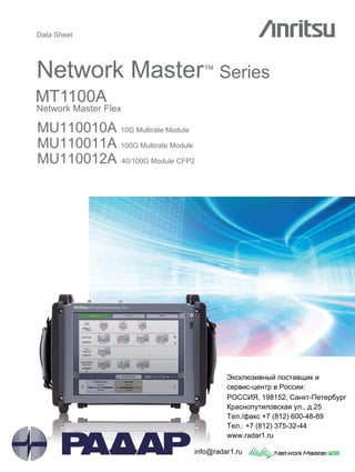
1. Data Sheet
Network Master™ Series
MT1100A
Network Master Flex
MU110010A 10G Multirate Module
MU110011A 100G Multirate Module
MU110012A 40/100G Module CFP2
Эксклюзивный поставщик и
сервис-центр в России:
, 198152, нкт- етербург
р снопутиловск я ул., д.25
ел./ф кс +7 (812) 600-48-89
ел.: +7 (812) 375-32-44
www.radar1.ru---
info@radar1.ru
2. 2 Data Sheet l MT1100A
Redefining Transport Testing
All-in-one Support for R&D, Manufacturing and I&M of 100 Gbps Core and Metro Networks
Today’s core and metro communications networks are implementing 100 GigE and OTN technologies rapidly to provide sufficient bandwidth
supporting the explosive increase in mobile communications data. These high-bit-rate networks demand very high reliability due to the large
data volumes and variety of client signals in use. Consequently, every stage from R&D through to manufacturing, installation, and maintenance,
requires precision testing and verification of network equipment and transport devices.
The all-in-one Network Master Flex MT1100A supports all the latest communications network technologies. Selecting and installing up to two
modules from a range of three module options supports all-in-one R&D, manufacturing, installation and maintenance tests of network and trans-
port equipment operating at bit rates from 1.5 Mbps to 100 Gbps. The large, 12.1-inch color LCD touch panel with easy-to-use GUI plus remote
operation of a full range of test functions over an Internet connection greatly improves test efficiency and helps cut costs.
Key Benefits and Features:
• All-in-one transport tester
– supports testing from 1.5 Mbps to 100 Gbps
• Up to 4 ports at all rates
• Easy and intuitive GUI
• WLAN*/Bluetooth*/LAN connectivity
• PDF and XML report generation for documenting test results
• Remote operation
• Remote control (scripting)
• Compact, lightweight design for maximum field portability
• High performance in small form factor
• Modular platform ensuring maximum return on investment
Key Applications:
• Core and metro networks installation and maintenance
• OTN up to OTU4 including mapping of Ethernet, Fibre Channel and SDH/SONET
client signals, multistage mapping and FEC (Forward Error Correction) also
supporting O.182 Poisson error addition
• Testing and verification of new OTN functions
ODU0, ODU2e, ODU3e1, ODU3e2, ODU4, ODUflex
• Carrier Class Ethernet installation and troubleshooting
• Ethernet testing up to 100 Gbps including RFC 2544 and Y.1564
• Ethernet OAM
• MPLS-TP and PBB/PBB-TE
• IP Channel Statistics (up to 10 Gbps)
• Frame capture for advanced troubleshooting
• Mobile backhaul installation and verification
• Synchronous Ethernet testing up to 10 Gbps (ITU-T G.826x, IEEE 1588 v2)
• Powerful Storage Area Networking (SAN) testing
• Fibre Channel up to 10 Gbps
• Quick and easy testing of SDH/SONET and PDH/DSn networks
• SDH/SONET (STM-1 to 256/OC-3 to 768)
• PDH/DSn (E1, E3, E4, DS1, DS3)
*: Available for certified countries and regions including USA, Canada, Japan and all EU countries. Please contact Anritsu for updated information.
The Bluetooth®
mark and logos are owned by Bluetooth SIG, Inc. and are used by Anritsu under license.
Connector Panel Overview
Power Supply Module
Battery and AC Power Supply Module MU110001A
AC only High Power Supply Module MU110002A
Test Module (Select one or two modules)
10G Multirate Module MU110010A
100G Multirate Module MU110011A
40/100G Module CFP2 MU110012A
Mainframe
Network Master Flex MT1100A
1 2 3 4 5 6 7 8 9
12.1-inch active TFT display and touch screen Power switch
Speaker
1 Unit Sync. Input (for future use)
2 Unit Sync. Output (for future use)
3 Audio
4 AUX (for G0325A, GPS receiver)
5 External Clock Input
6 USB Mini-B
7 USB A
8 USB A
9 Ethernet Service Interface
4. 4 Data Sheet l MT1100A
Configuration Guide
Mainframe and Modules
Product Number Product Name Description
MT1100A Network Master Flex Network Master Flex Mainframe
MU110001A Battery and AC Power Supply Module
Power supply module for MT1100A
Includes G0237A × 2 (Battery), Z1862A (Hexagon wrench)
MU110002A AC only High Power Supply Module
High power supply module for MT1100A
Includes Z1862A (Hexagon wrench)
MU110010A 10G Multirate Module SFP/SFP+: 2, RJ45: 2, BNC (Tx/Rx): 2, RJ48: 2, Mini-bantam (Tx/Rx): 2
MU110011A 100G Multirate Module CFP: 1, QSFP+: 2, SFP/SFP+: 2, RJ45: 2
MU110012A 40/100G Module CFP2 CFP2: 2, CXP: 2, QSFP+: 2
Power Supply Module
Test Modules
Mainframe
MU110001A or MU110002A
MT1100A
One or two modules in
MU110010A/11A/12A
One mainframe, one or two test modules and one
power supply module can be combined flexibly for
various applications.
Power Supply Modules and Test Modules Combination
MU110001A
Battery and AC
Supported Configuration
MU110010A
10G Multirate
Module
MU110011A
100G Multirate
Module
MU110012A
40/100G
Module CFP2
One Module
Two Modules
MU110002A
AC only
Supported Configuration
MU110010A
10G Multirate
Module
MU110011A
100G Multirate
Module
MU110012A
40/100G
Module CFP2
One Module
Two Modules
(Any two kinds of modules
can be combined)
Test Modules and Maximum Operating Ports
Protocol PDH/DSn OTU1
100 Mbps
to 1 Gbps
Ethernet
STM-16/
OC-48
1GFC to
4GFC
OTU2/1e/
2e/1f/2f
10 Gbps
Ethernet
STM-64/
OC-192
8GFC to
10GFC
OTU3/
3e1/3e2
40 Gbps
Ethernet
STM-256/
OC-768
OTU4
100 Gbps
Ethernet
MU110010A 2 ports 2 ports 2 ports
MU110011A 2 ports 2 ports 2 ports*1
1 port
MU110012A 2 ports *2 2 ports
*1: Up to two ports in two QSFP+ and one CFP can be operated simultaneously.
*2: MU110012A does not have a STM-256/OC-768 physical interface.
MU110012A-083/084 are the options for STM-256/OC-768 client signals mapped in the OTN. Please refer to page 6.
5. Data Sheet l MT1100A 5
OTN Mappings
Support the mappings of OTU1 and OTU2x in MU110010A
Support the mappings of OTU1 and OTU2x in MU110011A
OTU2 ODU/
OPU2
ODU/
OPU Flex
ODU/OPU1
ODTU01
(PT=20)
OTU1
PRBS
FC-400
FC-800
GFP-T
PRBS
STM-64/
OC-192
PRBS
STM-16/
OC-48
ODTU12
(PT=20)
ODTU12
(PT=21)
ODTU2.1
FC-200
PRBS
GigE
STM-4/STM-1
/OC-12/OC-3
FC-100
ODU/OPU0
BMP
GMP BMP
BMP
GMPGMP
GMP
BMP
AMP
GMP
AMP
AMP
AMP
AMP
OTU2e/1e ODU/OPU
2e/1e 10GigE
PRBS
AMP
ODU/OPU
2f/1f FC-1200
PRBS
AMPOTU2f/1f
MU110010A-001 Up to 2.7G Dual Port
MU110010A-051/052 OTN 10G Single/Dual Channel
MU110010A-061 ODU Multiplexing
MU110010A-062 ODU Flex
MU110010A-002 1G 2G 4GFC Dual Port
MU110010A-091/092 FC 8G 10G Single/Dual Channel
MU110010A-081/082 STM-64 OC-192 Single/Dual Channel
MU110010A-011/012 Ethernet 10G Single/Dual Channel
ODTU2.ts
GFP-F MAC/IP
OTU2 ODU/
OPU2
ODU/
OPU Flex
ODU/OPU1
ODTU01
(PT=20)
OTU1
PRBS
FC-400
FC-800
GFP-T
PRBS
STM-64/
OC-192
PRBS
STM-16/
OC-48
ODTU12
(PT=20)
ODTU12
(PT=21)
ODTU2.1
FC-200
PRBS
GigE
STM-4/STM-1
/OC-12/OC-3
FC-100
ODU/OPU0
BMP
GMP BMP
BMP
GMPGMP
GMP
BMP
AMP
GMP
AMP
AMP
AMP
AMP
OTU2e/1e ODU/OPU
2e/1e 10GigE
PRBS
AMP
ODU/OPU
2f/1f FC-1200
PRBS
AMPOTU2f/1f
MU110010A-061 ODU Multiplexing
MU110010A-062 ODU Flex
MU110011A/12A-003 Up to 10G Dual Port
MU110011A/12A-004 Up to 10G FC Dual Port
ODTU2.ts
GFP-F MAC/IP
6. 6 Data Sheet l MT1100A
Support the mappings of OTU3 in MU110011A/12A
Support the mappings of OTU4 in MU110011A/12A
OTU3 ODU/
OPU3
ODU/
OPU Flex PRBS
FC-400/
FC-800
PRBS
STM-256/
OC-768
PRBSODTU23
(PT=20)
ODTU3.1 PRBSODU/OPU0
BMP
GMP BMP
BMP
BMPGMP
GFP-T GigE
STM-4/STM-1
/OC-12/OC-3
GMP
FC-100GMP
GMP
STM-64/
OC-192AMP
AMP
40GigETCGMP
AMP
OTU3e1 ODU/OPU
3e1 PRBS
10GigE
BMP
ODU/OPU
3e2
ODU/OPU
2e
ODU/OPU
2e
ODTU
2e3e1
ODTU
3e2.8 PRBS
10GigE
BMP
AMP
AMP
AMP
GMPOTU3e2
MU110011A/12A-053/054 OTN 40G Single/Dual Channel
MU110011A/12A-061 ODU Multiplexing
MU110011A/12A-062 ODU Flex
MU110011A/12A-003 Up to 10G Dual Port
MU110011A/12A-004 Up to 10GFC Dual Port
MU110011A/12A-013/014 Ethernet 40G Single/Dual Channel
MU110011A/12A-083/084 STM-256 OC-768 Single/Dual Channel
ODTU3.ts
GFP-F MAC/IP
ODU/OPU2
ODTU23
(PT=21)
PRBSODTU13
(PT=20) BMP
STM-16/
OC-48AMP
FC-200GMP
AMP ODU/OPU1
ODTU23
(PT=21)
OTU4
ODU/
OPU Flex PRBS
FC-400/
FC-800
PRBS
PRBSODTU4.31
ODTU4.2 PRBSODU/OPU1
BMP
GMP BMP
BMP
BMPGMP
STM-16/
OC-48
AMP
FC-200GMP
ODTU4.1 PRBSODU/OPU0 BMPGMP
GFP-T GigE
STM-4/STM-1
/OC-12/OC-3
GMP
FC-100GMP
GMP
STM-256/
OC-768AMP
100GigEGMP
40GigETCGMP
GMP
MU110011A/12A-055/056 OTN 100G Single/Dual Channel
MU110011A/12A-061 ODU Multiplexing
MU110011A/12A-062 ODU Flex
MU110011A/12A-003 Up to Up to 10G Dual Port
MU110011A/12A-004 Up to 10G FC Dual Port
MU110011A/12A-015/016 Ethernet 100G Single/Dual Channel
MU110011A/12A-013/014 Ethernet 40G Single/Dual Channel
MU110011A/12A-083/084 STM-256 OC-768 Single/Dual Channel
ODTU4.ts
GFP-F MAC/IP
ODU/OPU3
PRBSBMP
STM-64/
OC-192AMP
GMP ODU/OPU2
PRBSBMP
10GigEAMP
ODU/OPU2e
ODU/
OPU4
ODTU4.8
8. 8 Data Sheet l MT1100A
Optical Transceivers
Model/Order No. Description (Approx. Distance)
Max. Input
Power
Input
Sensitivity
Input Wavelength Output Power Output Wavelength
Loop
Back
G0311A
1G 850 nm SX SFP
1000BASE - SX 850 nm
multi mode (0.5 km)
–3 dBm –17 dBm 770 nm to 860 nm –9.5 to –3 dBm 830 nm to 860 nm OK
G0312A
1G 1310 nm LX SFP
1000BASE - LX 1310 nm
single mode (10 km)
–3 dBm –18 dBm 1260 nm to 1580 nm –10 to –3 dBm 1260 nm to 1360 nm OK
G0313A
1G 1550 nm ZX SFP
1000BASE - ZX 1550 nm
single mode (80 km)
–3 dBm –23 dBm 1260 nm to 1580 nm –2 to +5 dBm 1480 nm to 1580 nm
8 dB
ATT
G0332A
100M FX 1310 nm MM SFP
100BASE - FX 1310 nm
multi mode (2 km)
–14 dBm –31 dBm 1270 nm to 1600 nm –20 to –15 dBm 1280 nm to 1380 nm OK
G0333A
10G SR/SW 850 nm SFP+
10GBASE - SR 850 nm
multi mode (0.3 km)
–1 dBm –11.1 dBm 840 nm to 860 nm –7.3 to –1.0 dBm 840 nm to 860 nm OK
G0356A
8G FC/10G SR 850 nm SFP+
8GFC, 10GFC,
10GBASE - SR 850 nm
multi mode (0.3 km)
–1 dBm –11.1 dBm 840 nm to 860 nm –7.3 to –1.0 dBm 840 nm to 860 nm OK
G0329A
10G LR 1310 nm SFP+
10GBASE - LR 1310 nm
single mode (10 km)
+0.5 dBm –14 dBm 1260 nm to 1355 nm –8.2 to +0.5 dBm 1260 nm to 1355 nm OK
G0315A
10G LR/LW 1310 nm SFP+
10GBASE - LR 1310 nm
single mode (10 km)
+0.5 dBm –14.4 dBm 1260 nm to 1565 nm –6 to –1 dBm 1290 nm to 1330 nm OK
G0316A
10G ER/EW 1550 nm 40 km SFP+
10GBASE - ER 1550 nm
single mode (40 km)
–1 dBm –15.8 dBm 1260 nm to 1565 nm –3 to +3 dBm 1530 nm to 1560 nm
4 dB
ATT
G0318A
10G ZR/ZW 1550 nm 80 km SFP+
10GBASE - ER 1550 nm
single mode (80 km)
–8 dBm –22 dBm 1260 nm to 1565 nm 0 to +5 dBm 1525 nm to 1565 nm
13 dB
ATT
G0319A
Up to 2.7G 1310 nm 15 km SFP
STM-1/4/16 short haul 1310 nm
single mode (15 km)
0 dBm –18 dBm 1270 nm to 1580 nm –5 to 0 dBm 1260 nm to 1360 nm OK
G0320A
Up to 2.7G 1310 nm 40 km SFP
STM-1/4/16 long haul 1310 nm
single mode (40 km)
–9 dBm –27 dBm 1270 nm to 1580 nm –2 to +3 dBm 1280 nm to 1335 nm
12 dB
ATT
G0321A
Up to 2.7G 1550 nm 80 km SFP
STM-1/4/16 long haul 1550 nm
single mode (80 km)
–9 dBm –28 dBm 1270 nm to 1580 nm –2 to +3 dBm 1500 nm to 1580 nm
12 dB
ATT
G0328A
1G/2G/4G FC 850 nm SFP
1GFC, 2GFC, 4GFC 850 nm
multi mode (0.5 km)
–3 dBm –15 dBm 830 nm to 860 nm –9 to 0 dBm 830 nm to 860 nm
3 dB
ATT
G0322A
1G/2G/4G FC 1310 nm SFP
1GFC, 2GFC, 4GFC 1310 nm
single mode (10 km)
–3 dBm –18 dBm 1260 nm to 1360 nm –8 to 0 dBm 1260 nm to 1360 nm
3 dB
ATT
G0323A
1G/2G/4G FC 1550 nm SFP
1GFC, 2GFC, 4GFC 1550 nm
single mode (40 km)
–3 dBm –18 dBm 1470 nm to 1600 nm 0 to +5 dBm 1510 nm to 1590 nm
8 dB
ATT
G0334A
40G LR4 1310 nm QSFP+
40G Ethernet/OTN 1310 nm
single mode (10 km)
+2.3 dBm
(per Lane)
–11.5 dBm
(per Lane)
1264.5 nm to 1277.5 nm
1284.5 nm to 1297.5 nm
1304.5 nm to 1317.5 nm
1324.5 nm to 1337.5 nm
+8.3 dBm max. (Total)
–2 to +2.3 dBm
(per Lane)
1264.5 nm to 1277.5 nm
1284.5 nm to 1297.5 nm
1304.5 nm to 1317.5 nm
1324.5 nm to 1337.5 nm
OK
G0335A
40G LR4 1310 nm CFP
40G Ethernet/OTN 1310 nm
single mode (10 km)
+2.3 dBm
(per Lane)
–11.1 dBm
(per Lane)
1264.5 nm to 1277.5 nm
1284.5 nm to 1297.5 nm
1304.5 nm to 1317.5 nm
1324.5 nm to 1337.5 nm
+8.3 dBm max. (Total)
–2 to +2.3 dBm
(per Lane)
1264.5 nm to 1277.5 nm
1284.5 nm to 1297.5 nm
1304.5 nm to 1317.5 nm
1324.5 nm to 1337.5 nm
OK
G0336A
40G FR 1550 nm CFP
40G SDH/OTN 1550 nm
single mode (2 km)
+3 dBm
(per Lane)
–6 dBm 1530 nm to 1565 nm 0 to +3 dBm 1530 nm to 1565 nm OK
G0337A
100G LR4 1310 nm CFP
100G Ethernet/OTN 1310 nm
single mode (10 km)
+4.5 dBm
(per Lane)
–10.3 dBm
(per Lane)
1294.53 nm to 1296.59 nm
1299.02 nm to 1301.09 nm
1303.54 nm to 1305.63 nm
1308.09 nm to 1310.19 nm
+8.9 dBm max. (Total)
–2.9 to +2.9 dBm
(per Lane)
1294.53 nm to 1296.59 nm
1299.02 nm to 1301.09 nm
1303.54 nm to 1305.63 nm
1308.09 nm to 1310.19 nm
OK
G0338A
100G LR4 1310 nm CFP2
100G Ethernet/OTN 1310 nm
single mode (10 km)
+4.5 dBm
(per Lane)
–10.3 dBm
(per Lane)
1294.53 nm to 1296.59 nm
1299.02 nm to 1301.09 nm
1303.54 nm to 1305.63 nm
1308.09 nm to 1310.19 nm
+8.9 dBm max. (Total)
–2.9 to +2.9 dBm
(per Lane)
1294.53 nm to 1296.59 nm
1299.02 nm to 1301.09 nm
1303.54 nm to 1305.63 nm
1308.09 nm to 1310.19 nm
OK
G0339A
100G 850 nm CXP
100G Ethernet 850 nm
multi mode (0.1 km)
+2.4 dBm
(per Lane)
–9.5 dBm
(per Lane)
840 nm to 860 nm
+8.9 dBm max. (Total)
–7.6 to +2.4 dBm
(per Lane)
840 nm to 860 nm OK
MU110010A
MU110011A
MU110012A
Model/
Order No.
Name
FormFactor
100M
Ethernet
156M
SDH/SONET
622M
SDH/SONET
1GFC
1GEthernet
2GFC
2.5G
SDH/SONET
2.7GOTN
4GFC
8GFC
10G
SDH/SONET,
10G
WAN-PHY
10G
LAN-PHY
Ethernet
10GFC
10GOTN
40G
SDH/SONET
40G
Ethernet
40GOTN
100G
Ethernet
100GOTN
G0311A 1G 850 nm SX SFP SFP
G0312A 1G 1310 nm LX SFP SFP
G0313A 1G 1550 nm ZX SFP SFP
G0332A 100M FX 1310 nm MM SFP SFP
G0333A 10G SR/SW 850 nm SFP+ SFP+
G0356A 8G FC/10G SR 850 nm SFP+ SFP+
G0329A 10G LR 1310 nm SFP+ SFP+
G0315A 10G LR/LW 1310 nm SFP+ SFP+
G0316A 10G ER/EW 1550 nm 40 km SFP+ SFP+
G0318A 10G ZR/ZW 1550 nm 80 km SFP+ SFP+
G0319A Up to 2.7G 1310 nm 15 km SFP SFP
G0320A Up to 2.7G 1310 nm 40 km SFP SFP
G0321A Up to 2.7G 1550 nm 80 km SFP SFP
G0328A 1G/2G/4G FC 850 nm SFP SFP
G0322A 1G/2G/4G FC 1310 nm SFP SFP
G0323A 1G/2G/4G FC 1550 nm SFP SFP
G0334A 40G LR4 1310 nm QSFP+ QSFP+
G0335A 40G LR4 1310 nm CFP CFP
G0336A 40G FR 1550 nm CFP CFP
G0337A 100G LR4 1310 nm CFP CFP
G0338A 100G LR4 1310 nm CFP2 CFP2
G0339A 100G 850 nm CXP CXP
850 nm, MM, 0.5 km
1550 nm, SM, 80 km
1310 nm, SM, 10 km
1310 nm, SM, 15 km
1550 nm, SM, 80 km
1310 nm, SM, 40 km
1310 nm, MM, 2 km
1550 nm, SM, 80 km
850 nm, MM, 0.3 km
850 nm, MM, 0.5 km
1310 nm, SM, 10 km
1310 nm, SM, 10 km
1310 nm, SM, 10 km
1310 nm, SM, 10 km
1310 nm, SM, 10 km
1310 nm, SM, 10 km
850 nm, MM,
0.1 km
1550 nm, SM, 40 km
1550 nm, SM, 40 km
1550 nm, SM, 2 km
1310 nm,
SM, 10 km
850 nm, MM, 0.3 km
9. Data Sheet l MT1100A 9
Specifications
Network Master Flex MT1100A Mainframe
User Interface
Display 12.1-inch active matrix TFT display (800 × 600 pixels) and touch screen
Service Interface
USB Interface MT1100A operates as host: USB 2.0 type A (2 ports)
MT1100A operates as device: USB 2.0 type Mini-B (1 port)
Ethernet Interface Ethernet 10M/100M/1000M, Connector: RJ45
WLAN Interface* IEEE 802.11 b/g/h
Bluetooth Interface* Bluetooth 2.1 + EDR
∗: Available for certified countries and regions including USA, Canada, Japan and all EU countries. Please contact Anritsu for updated information.
Other Interfaces
Unit synchronization Input (Not used)
Unit Synchronization Output (Not used)
Audio Interface For connection of optional head set
Connector: 3.5-mm diameter jack
AUX Connector For connection of G0325A GPS receiver
Built-in Loudspeaker Monitors speech of voice channel
Output level: user-controlled from user Interface
Ext. Clock Input For connection of external clock signals:
SETS (E1: 2.048 Mbps), BITS (DS1: 1.544 Mbps),or 2.048 MHz TTL signal in accordance with ITU-T G.703
Connector: BNC
Miscellaneous
Dimensions and Mass 320 (W) × 225 (H) × 46 (D) mm (without protector), ≤2.5 kg
Environmental Temperature and Humidity
Operating: 0° to +40°C, ≤80% RH (non-condensing)
Storage: –20° to +60°C, ≤80% RH (non-condensing)
EMC EN61326-1, EN61000-3-2
LVD EN61010-1
Battery and AC Power Supply Module MU110001A
Battery 14.4 V rechargeable and replaceable intelligent Li-ion battery
Operation time: 1 hour (typ.) (with MU110011A, 100 Gbps Ethernet operation)
Charging time: 6 hours (typ.) (25°C)
Remaining capacity indication:%
Power Supply 100 V(ac) to 240 V(ac), 50 Hz/60 Hz
380 VA (Max.)
Dimensions and Mass 320 (W) × 225 (H) × 82 (D) mm (without protector), ≤3.0 kg (without battery)
Environmental Temperature and Humidity
Operating: 0° to +40°C, ≤80% RH (non-condensing)
Storage: –20° to +60°C, ≤80% RH (non-condensing, without battery)
–20° to +50°C, ≤80% RH (non-condensing, with battery)
EMC EN61326-1, EN61000-3-2
LVD EN61010-1
AC only High Power Supply Module MU110002A
Power Supply 100 V(ac) to 240 V(ac), 50 Hz/60 Hz
700 VA (Max.)
Dimensions and Mass 320 (W) × 225 (H) × 72 (D) mm (without protector), ≤3.0 kg
Environmental Temperature and Humidity
Operating: 0° to +40°C, ≤80% RH (non-condensing)
Storage: –20° to +60°C, ≤80% RH (non-condensing)
EMC EN61326-1, EN61000-3-2
LVD EN61010-1
10. 10 Data Sheet l MT1100A
10G Multirate Module MU110010A
Test Port SFP/SFP+: 2 slots
SFF-8431, SFF-8472 compliant, IEEE 802.3ae-2002, IEEE 802.3-2008 compliant
RJ45: 2 sockets
IEEE 802.3-2008 10BASE-T, 100BASE-TX, 1000BASE-T compliant
Auto MDI-X
10 Mbps/100 Mbps full/half duplex, 1000 Mbps full duplex
BNC: 4 ports
ITU-T G.703 compliant
RJ48: 2 sockets
ITU-T G.703 compliant
RTT Bantam: 4 ports
ANSI DS1.102 compliant
Bit Rate*1
Standard Bit Rate Interfaces
10BASE-T 12.50000000 Mbps RJ45
100BASE-TX 125.0000000 Mbps RJ45
1000BASE-T 1.250000000 Gbps RJ45
100BASE-XX 125.0000000 Mbps SFP
1000BASE-XX 1.250000000 Gbps SFP
10GBASE-XX 10.31250000 Gbps SFP+
STM-1/OC-3 155.5200000 Mbps SFP
STM-4/OC-12 622.0800000 Mbps SFP
STM-16/OC-48 2.488320000 Mbps SFP
STM-64/OC-192 9.953280000 Mbps SFP+
OTU1 2.666057143 Gbps SFP
OTU2 10.70922532 Gbps SFP+
OTU1e 11.04910714 Gbps SFP+
OTU2e 11.09572785 Gbps SFP+
Standard Bit Rate Interfaces
OTU1f 11.27008929 Gbps SFP+
OTU2f 11.31764241 Gbps SFP+
10GFC 10.51875000 Gbps SFP+
8GFC 8.500000000 Gbps SFP+
4GFC 4.250000000 Gbps SFP
2GFC 2.125000000 Gbps SFP
1GFC 1.062500000 Gbps SFP
E1 2.048000000 Mbps RJ48, BNC
E3 34.36800000 Mbps BNC
E4 139.2640000 Mbps BNC
DS1 1.544000000 Mbps RTT Bantam
DS3 44.73600000 Mbps BNC
STM-1e/STS-3 155.5200000 Mbps BNC
Tx Ref. Clock Output Frequency
Selectable from 1/16, or 1/64 against the bit rate of the lane. (Available only when an SFP+ port is selected)
Level: 250 mVp-p (Min.), 550 mVp-p (Max.)
Termination: 50Ω/AC (Single ended)
Connector: SMA
Dimensions and Mass 320 (W) × 225 (H) × 37 (D) mm, ≤1.4 kg
Environmental Temperature and Humidity
Operating: 0° to +40°C, ≤80% RH (non-condensing)
Storage: –20° to +60°C, ≤80% RH (non-condensing)
EMC EN61326-1, EN61000-3-2
LVD EN61010-1
Laser Safety*3 IEC 60825-1: 2007 CLASS 1
21CFR1040.10 and 1040.11*2
*1: The frequency accuracy depends on the accuracy of the MT1100A internal clock or the external clock of MT1100A.
Refer to the external interfaces in MT1100A specifications.
∗2: Excludes deviations caused by conformance to Laser Notice No. 50 dated June 24, 2007
∗3: Safety measures for laser products
This product complies with optical safety standards in 21CFR1040.10, 1040.11 and IEC 60825-1; the following descriptive labels are affixed to the product.
11. Data Sheet l MT1100A 11
100G Multirate Module MU110011A
Test Port CFP: 1 slot
CFP MSA Hardware Specification, Rev. 1.4 compliant
CFP MSA Management Interface Specification V2.2 R06a compliant (Not supported to MSA 100GLH)
IEEE 802.3ba-2010 compliant
QSFP+: 2 slots
SFF-8436, SFF-8472 compliant
IEEE 802.3ba-2010 compliant
SFP/SFP+: 2 slots
SFF-8431, SFF-8472 compliant
IEEE 802.3ae-2002, IEEE 802.3-2008 compliant
RJ45: 2 sockets
IEEE 802.3-2008 10BASE-T, 100BASE-TX, 1000BASE-T compliant
Auto MDI-X
10 Mbps/100 Mbps full/half duplex, 1000 Mbps full duplex
Bit Rate*1
Standard Bit Rate Interfaces
10BASE-T 12.50000000 Mbps RJ45
100BASE-TX 125.0000000 Mbps RJ45
1000BASE-T 1.250000000 Gbps RJ45
100BASE-XX 125.0000000 Mbps SFP
1000BASE-XX 1.250000000 Gbps SFP
10GBASE-XX 10.31250000 Gbps SFP+
40 GigE 10.31250000 Gbps
× 4 Lane
CFP, QSFP+
100 GigE 10.31250000 Gbps
× 10 Lane
CFP
STM-1/OC-3 155.5200000 Mbps SFP
STM-4/OC-12 622.0800000 Mbps SFP
STM-16/OC-48 2.488320000 Mbps SFP
STM-64/OC-192 9.953280000 Mbps SFP+
STM-256/OC-768 9.953280000 Mbps
× 4 Lane
CFP
OTU1 2.666057143 Gbps SFP
OTU2 10.70922532 Gbps SFP+
Standard Bit Rate Interfaces
OTU1e 11.04910714 Gbps SFP+
OTU2e 11.09572785 Gbps SFP+
OTU1f 11.27008929 Gbps SFP+
OTU2f 11.31764241 Gbps SFP+
OTU3 10.75460339 Gbps
× 4 Lane
CFP, QSFP+
OTU3e1 11.14274364 Gbps
× 4 Lane
CFP, QSFP+
OTU3e2 11.14583889 Gbps
× 4 Lane
CFP, QSFP+
OTU4 11.18099736 Gbps
× 10 Lane
CFP
1GFC 1.062500000 Gbps SFP
2GFC 2.125000000 Gbps SFP
4GFC 4.250000000 Gbps SFP
8GFC 8.500000000 Gbps SFP+
10GFC 10.51875000 Gbps SFP+
Tx Ref. Clock Output Frequency
Selectable from 1/16, or 1/64 against the bit rate of the lane. (RJ45 port cannot be selected)
Level: 250 mVp-p (Min.), 550 mVp-p (Max.)
Termination: 50Ω/AC (Single ended)
Connector: SMA
AUX Connector Termination: 50Ω/AC (Single ended)
Connector: SMA
Dimensions and Mass 320 (W) × 225 (H) × 60 (D) mm, ≤3.0 kg
Environmental Temperature and Humidity
Operating: 0° to +40°C, ≤80% RH (non-condensing)
Storage: –20° to +60°C, ≤80% RH (non-condensing)
EMC EN61326-1, EN61000-3-2
LVD EN61010-1
Laser Safety*3 CFP: 100GBASE-LR4, 40GBASE-LR4, 40GBASE-FR
QSFP+: 40GBASE-LR4
SFP: 4GFC(SX), 4GFC(LX), 4GFC(EX), OC-48 LR-1/STM L-16.1, OC-48 LR-2/STM L-16.2, 100BASE-FX, 100BASE-LX
SFP+: 1000BASE-SX/LX/ZX, 10GBASE-LR, 10GBASE-ER, 10GBASE-ZR
IEC 60825-1: 2007 CLASS 1
21CFR1040.10 and 1040.11*1
CFP: 100G BASE-SR10
QSFP+: 40GBASE-SR4
IEC 60825-1: 2007 CLASS 1M
21CFR1040.10 and 1040.11*1
*1: The frequency accuracy depends on the accuracy of the MT1100A internal clock or the external clock of MT1100A.
Refer to the external interfaces in MT1100A specifications.
∗2: Excludes deviations caused by conformance to Laser Notice No. 50 dated June 24, 2007
∗3: Safety measures for laser products
This product complies with optical safety standards in 21CFR1040.10, 1040.11 and IEC 60825-1; the following descriptive labels are affixed to the product.
12. 12 Data Sheet l MT1100A
40/100G Module CFP2 MU110012A
Test Port CFP2: 2 slots
CFP MSA CFP2 Hardware Specification, Rev. 1.0 compliant
CFP MSA Management Interface Specification V2.2 R06a compliant (Not supported to MSA 100GLH)
IEEE 802.3ba-2010 compliant
CXP: 2 slots
InfiniBand Architecture 1.2.1 Annex A6: CXP compliant
SFF-8642, IEEE 802.3ba-2010 compliant
QSFP+: 2 slots
SFF-8436, SFF-8472 compliant
IEEE 802.3ba-2010 compliant
Bit Rate*1
Standard Bit Rate Interfaces
40 GigE 10.31250000 Gbps × 4 Lane QSFP+
100 GigE 10.31250000 Gbps × 10 Lane CXP
100 GigE 25.781250000 Gbps × 4 Lane CFP2
OTU3 10.75460339 Gbps × 4 Lane QSFP+
OTU3e1 11.14274364 Gbps × 4 Lane QSFP+
OTU3e2 11.14583889 Gbps × 4 Lane QSFP+
OTU4 27.952493392 Gbps × 4 Lane CFP2
Tx Ref. Clock Output Frequency
Selectable from 1/16, or 1/64 against the bit rate of the lane.
40 GigE: QSFP+
100 GigE: CXP
OTU3: QSFP+
OTU3e1: QSFP+
OTU3e2: QSFP+
Selectable from 1/40, or 1/160 against the bit rate of the lane.
100 GigE: CFP2
OTU4: CFP2
Level: 250 mVp-p (Min.), 550 mVp-p (Max.)
Termination: 50Ω/AC (Single ended)
Connector: SMA
AUX Connector Termination: 50Ω/AC (Single ended)
Connector: SMA
Dimensions and Mass 320 (W) × 225 (H) × 69 (D) mm, ≤3.0 kg
Environmental Temperature and Humidity
Operating: 0° to +40°C, ≤80% RH (non-condensing)
Storage: –20° to +60°C, ≤80% RH (non-condensing)
EMC EN61326-1, EN61000-3-2
LVD EN61010-1
Laser Safety*3
CFP2: 100GBASE-LR4
QSFP+: 40GBASE-LR4
IEC 60825-1: 2007 CLASS 1
21CFR1040.10 and 1040.11*2
CXP: 100G BASE-SR10
QSFP+: 40GBASE-SR4
IEC 60825-1: 2007 CLASS 1M
21CFR1040.10 and 1040.11*2
*1: The frequency accuracy depends on the accuracy of the MT1100A internal clock or the external clock of MT1100A.
Refer to the external interfaces in MT1100A specifications.
∗2: Excludes deviations caused by conformance to Laser Notice No. 50 dated June 24, 2007
∗3: Safety measures for laser products
This product complies with optical safety standards in 21CFR1040.10, 1040.11 and IEC 60825-1; the following descriptive labels are affixed to the product.
13. Data Sheet l MT1100A 13
Specifications for MU110010A, MU110011A, MU110012A
OTN Testing
OTN Test
Framing Complies with ITU-T G.709 [at each OTU rate]
FEC: Complies with G.709, RS (255, 239), On/Off
Transmitter Clock • Internal clock accuracy: 4.6 ppm, Clock offset: ±200 ppm (0.1-ppm steps)
• Received clock
• TTL level external 2 MHz clock
• SETS (E1: 2.048 Mbps), BITS (DS1: 1.544 Mbps)
• Signal from optional GPS receiver
Receive Signal Rate ±200 ppm
Frequency deviation indication resolution: ±0.1 ppm
Scrambling Complies with ITU-T G.709
OTN Mapping See page 5, 6
OTN Alarm Detected alarms
• OTU layer: OTU-AIS, LOF, OOF, LOM, OOM, SM-TIM, SM-BIAE, SM-BDI, SM-IAE
• ODU layer: ODU-AIS, ODU-OCI, ODU-LCK, PM-TIM, PM-BDI
• ODU multiplexing: ODU-LOFLOM, ODU-OOF
• OPU layer: PLM, OPU-MSIM, Client-AIS, CSF. LSS
• TCM: TCMi-TIM, TCMi-BIAE, TCMi-BDI, TCMi-IAE, TCMi-LTC (i = 1 to 6)
• OTL: LOF, OOF, OOR, LOR, OOM, LOM, ILA/OLA (OTU3, 3e1, 3e2, 4)
Generated alarms
• OTU layer: OTU-AIS, OTU-OOF/LOF, OOM/LOM, SM-TIM, SM-BIAE, SM-BDI, SM-IAE
• ODU layer: ODU-AIS, ODU-OCI, ODU-LCK, PM-TIM, PM-BDI
• ODU multiplexing: ODU-OOF/LOF, ODU-OOM/LOM
• OPU layer: Client-AIS, CSF
• TCM: TCMi-TIM, TCMi-BIAE, TCMi-IAE, TCMi-BDI, TCMi-LTC (i = 1 to 6)
• OTL: LOF, OOF, OOR, LOR (OTU3, 3e1, 3e2, 4)
OTN Error Detected errors
• OTU layer: FAS, MFAS, SM-BEI, SM-BIP8, FEC-Correctable, FEC-Uncorrectable
• ODU layer: PM-BIP8, PM-BEI
• OPU layer: Pattern error
• GMP error: CRC8 error, CRC5 error
• GFP-T errors: Core HEC-Correctable errors, Core HEC-Uncorrectable errors, Type HEC-Correctable errors,
Type HEC-Uncorrectable errors, CSF signal, CSF sync., Invalid GFP frame, Superblock CRC error
• TCM: TCMi-BEI, TCMi-BIP-8 (i = 1 to 6)
• OTL: FAS, MFAS, LLM (OTU3, 3e1, 3e2, 4)
Generated errors
• OTU layer: Bit all, OTU-FAS, MFAS, SM-BIP8, SM-BEI
• ODU layer: PM-BIP8, PM-BEI, ODU-FAS
• TCMi-BIP8, TCMi-BEI (i = 1 to 6)
• Pattern error
• OTL: FAS, MFAS, LLM (OTU3, 3e1, 3e2, 4)
Error Performance • G.8201/M.2401 analysis of received signal based on detected errors and alarms: BBE, BBER, SES, SESR, UNAV
Justification Justification (per AMP)
• Negative (–1)
• Positive (+1)
• Positive (+2)
• Offset (ppm)
Cm(t) (per GMP)
• Can be set Offset (ppm)
BER Test Pattern Pattern generation and detection for bulk test patterns:
• Test patterns: PRBS 9, PRBS 11, PRBS 15, PRBS 20, PRBS 23, PRBS 29, PRBS 31
PRBS patterns can be inverted.
• User-defined patterns (Pattern length: up to 2048 bits, Length step: 8 bits)
FEC Test ITU-T O.182 Random error insertion
Overhead User-editable header bytes
• OTU layer: FAS, SM, GCC0, RES
• ODU layer: PM, FTFL, APS/PCC, GCC1, GCC2, RES, EXP, TCMi (i = 1 to 6)
• OPU layer(s): PSI
Capture and display current overhead bytes
The following signals are decoded: TTI (SM, PM, TCMi (i = 1 to 6) of high-order, FTFL, PT)
OTL Skew OTU3, 3e1, 3e2, 4
Insertion
Bits: 0 to 32000 (Tx lane)
Detection
Relative skew, Marker map
Through Mode • Transparent mode
• OH overwrite mode
The OTU, ODU and OPU overhead can be changed.
The FEC encoder and decoder can be set On/Off in any mode
14. 14 Data Sheet l MT1100A
OTN Result
Status Current information on:
• Alarms and errors on monitored line
• Input level indication for optical signals
• Frequency
• Frequency deviation
Statistics User-defined measurement resolution: 1, 2, 5, 10, 15, 30 s, 1, 5, 10, 15, 30 min, 1, 2, 4, 6, 12 h
Logged information: Alarms (s), Errors (count or count and ratio)
APS APS (Automatic Protection Switching) test and analysis
• APS switching time is measured. A switching time exceeding the user-defined threshold is highlighted.
• Start and stop triggers can be selected independently.
• Trigger events can be selected from the high-order OTU and ODU.
• Switching time, Switching count, Pass/Fail, Minimum, Maximum and Average can be displayed.
APS switching time measurement resolution: 0.1 ms
Round Trip Delay (Propagation
Time) Measurement
Resolution: 0.1 µs
Measured Max. time: 10.0 s
Interval: 0.5, 1, 2, 5, 10 s
Tributary Scan Supports up to 10 Gbps
Detected alarms:
OTU-AIS, LOF, OOF, LOM, OOM, SM-BIAE, SM-BDI, SM-IAE, ODU-AIS, ODU-OCI, ODU-LCK, PM-BDI, LOFLOM
Ethernet Testing
Ethernet Test
Test Configuration • Monitor/Generate, Pass-through, Reflector
Encapsulation • EtherType II (DIX v.2), IEEE 802.3 with 802.2 (LLC1), IEEE 802.3 with SNAP
Configuration, Monitor/Generate
Traffic Generation • Variable line rate traffic generation, up to full line rate
• Line load profile: Constant, Ramp
• Traffic duration: Continuous, Programmable number of seconds or frames
• Adjustable frame size: 44 bytes to 16000 bytes
• Frame sizes: Constant, Stepped, Random
• Payload profiles: Data, Video, Voice
• User-defined traffic mix of unicast and broadcast frames
• Fixed or incremented IP identifier
• User programmable DSCP/TOS byte
• Configurable IP and Ethernet source and destination addresses (supports IPv4 and IPv6 addressing)
IPv4: Fixed, DHCP, DNS
IPv6: Fixed
• Address increment, Decrement and Random generation supported
• User programmable UDP/TCP address
• Automatic TCP connect (user selectable)
• UDP check sum: Automatic, Fixed (null); TCP check sum: Automatic
• Generate pause frames, Respond to pause frames
• Answer incoming ARP, Ping requests (On/Off)
Stacked VLAN Up to 8 user-settable VLAN tags
Parameters per VLAN tag:
• Ether-type 0x8100 (802.1Q), 0x88a8 (802.1ad), 0x9100 or 0x9200
• User-defined VLAN ID, CFI, VLAN priority
• Address increment, Decrement and Random generation supported
Only one VLAN level supported at ping, traceroute and RFC 2544 router latency tests
Multistream Number of streams: Up to 16 streams per port can be activated
Timing Functionality Timing sources (selectable): Internal, Received clock, 2-MHz signal, SETS (E1: 2.048 Mbps), BITS (DS1: 1.544 Mbps),
PTP (IEEE 1588 v2) recovered clock or signal from optional GPS receiver
Frequency deviation: ±200 ppm (0.1-ppm steps)
The frequency deviation of received Ethernet signals can be measured against the internal clock.
Receiver Setting • User-defined expected preamble length: 3 bytes to 15 bytes
• User-defined IFG lower threshold: 8 bytes to 15 bytes (Ethernet 10 Mbps, 100 Mbps, 1000 Mbps)
• User-defined Jumbo frame size upper limit: 1519 bytes to 16000 bytes
Error Generation FCS, Preamble, Error symbol, IFG for ethernet 10 Mbps, 100 Mbps, 1000 Mbps, Wrong IP check sum, Fragmented IP,
Wrong layer 4 check sum, PRBS bit error, BER test sequence error
40 Gbps/100 Gbps: Invalid block type (0x00, 0x2d, 0x33, 0x66), Invalid sync. header (00, 11), Invalid alignment marker, BIP error
Alarm Generation No link, Remote fault, Local fault (10 Gbps)
PCS 40 Gbps/100 Gbps: High BER
PCS Skew 40 Gbps, 100 Gbps
Insertion
100 Gbps Tx lane: 0 to 4224 bits
40 Gbps, 100 Gbps physical lane: 0 to 8448
Detection
Relative skew, Marker map
15. Data Sheet l MT1100A 15
Result, Monitor/Generate
Status • Link status, Interface type, Jabber detected, Frames present, MPLS/EoMPLS/VLAN, Speed, Full or half duplex,
Local clock (Ethernet 1000 Mbps), LFS LF/RF (Ethernet 10 Gbps), Signal present, Bit rate of incoming Ethernet signal,
Auto negotiation complete
• Link partner abilities: Pause capable and Asymmetric pause request (not Ethernet 10 Gbps), Remote fault, Speed/Duplex
• Indicators for Utilization, Throughput and Errored frames
• Signal level indication for optical Ethernet interfaces
Resolution User-defined resolution for statistical measurements:
1 s, 2 s, 5 s, 10 s, 15 s, 30 s, 1 min, 5 min, 10 min, 15 min, 30 min, 1 h, 2 h, 4 h, 6 h, 12 h
Performance Statistics • Utilization (Max./Min./Avg.), Throughput (Max./Min./Avg.), Frame rate (Max./Min./Avg.)
Frame Statistics • Total frames, Total valid frames, Unicast/Multicast/Broadcast frames, Number of pause frames
• Number of VLAN tagged frames, Max. number of VLAN layers detected, Last received VLAN ID, Last received VLAN priority
• Number of MPLS frames and MPLS-TP frames. Max. number of MPLS layers detected. Last received MPLS Label,
MPLS Priority and MPLS TTL.
• Number of PBB frames. Last received B/I-tag ID and B/I-tag priority.
• Total errored frames, Fragmented frames, Number of oversized and undersized (runts) frames, Number of FCS errored
frames, Error symbol frames (not Ethernet 10 Gbps)/Code violation frames (Ethernet 10 Gbps), Number of collisions (10 Mbps,
100 Mbps half duplex), Preamble violations, IFG violations (Ethernet 10 Mbps, 100 Mbps, 1000 Mbps), False carrier,
10G LFS LF (local fault), 10G LFS RF (remote fault)
Burst Statistics Total frames, Total valid frames, Number of burst, Total frames in bursts, Burst size (Max./Min./Avg.)
Frame Distribution Statistics • Total valid/ frames, 64 to 127, 128 to 255, 256 to 511, 512 to 1023, 1024 to 1518 byte frames, Total number of jumbo frames
• Frame size (Max./Min./Avg.)
Multistream Statistics Available information per stream:
• Frame loss count/rate, Throughput, Latency, Packet jitter, Frames and bytes received and transmitted
Transmit Statistics Total frames, Total valid frames, Unicast/Multicast/Broadcast frames, FCS errors, Total errors
64 to 127, 128 to 255, 256 to 511, 512 to 1023, 1024 to 1518 byte frames, Total number of jumbo frames
Total number of frames (Tx (own port) – Rx (selectable port))
Filter Up to 8 filter conditions can be defined.
Each condition can filter using:
IP or MAC source address, IP or MAC destination address, Broadcast address, IEEE OUI value, Encapsulation type,
VLAN ID and VLAN tag priority, MPLS, PBB source and destination MAC address, PBB B/I-tag, MPLS-TP source and
destination MAC address, TPC/UDP source and destination port, User-defined pattern at defined offset
Adjustable Thresholds Utilization, Throughput, Errored frames, Collision rate, Unicast frames, Multicast frames, Broadcast frames, Pause frames,
Fragmented frames, Undersized frames (runts), Oversized frames, FCS errored frames, IFG violations (Ethernet 10 Mbps,
100 Mbps, 1000 Mbps), Preamble violations, BER test pattern errors, Sequence errors, Diff.Tx-Rx
DHCP • Display source IP address assigned by DHCP
• Display current lease expire time
• Display IP addresses of primary and secondary DNS server when obtained by DHCP
• Gateway setup using DHCP
BER Test and Service Disruption Measurement
BER Test Generation and detection of test patterns, Count of errors in received test pattern, Pattern generation: Unframed (Layer 1),
Framed Ethernet (MAC) header (Layer 2), Framed Ethernet (MAC) header with IP header (Layer 3) or Framed Ethernet (MAC)
header, Framed with IP header and TCP/UDP header (Layer 4)
Detection of sequence errors and loss of sequence synchronization
Frame loss count and frame loss seconds
Throughput measurement results are calculated for:
• Utilization layer, Physical layer, Physical layer excluding preamble, Link layer, Network layer and Data layer
• Min./Max./Avg. values
Performance (M.2100 type) parameters: ES, SES, ALS, UAT, AVT, EFS
Test patterns: PRBS 9, PRBS 11, PRBS 15, PRBS 20, PRBS 23, PRBS 29, PRBS 31, HF test pattern, CRPAT, JTPAT,
SPAT, 55 Hex, Fox, 32-bit user programmable
User-defined resolution: 1, 2, 5, 10, 15, 30 s, 1, 5, 10, 15, 30 min, 1, 2, 4, 6, 12 h
Error Generation FCS, Preamble, Error symbol, IFG for Ethernet (10 Mbps, 100 Mbps, 1000 Mbps), Wrong IP check sum, Fragmented IP,
Wrong layer 4 check sum, PRBS bit error, BER test sequence error
Alarm Generation No link, Remote fault
Service Disruption Measurement Service disruption measurement activated as part of BER test
• Max./Avg. service disruption time, Resolution: 0.1 µs
• Number of service disruptions
RFC 2544 Test
RFC 2544 Test Switch/Router test and Single ended network test modes:
• Throughput, Frame loss, Latency or Packet jitter, Back-to-back frames (burstability)
End-to-end network test mode (two MU110010A units in Local-remote setup)
• Throughput, Frame loss, Back-to-back frames (burstability)
Router latency test mode: IP ping based latency test or packet jitter
16. 16 Data Sheet l MT1100A
Service Activation Test (Y.1564)
Service Activation Test ITU-T Y.1564 Service Activation Test
• Up to 8 services per port
• Color-aware and non-color-aware in combinations (IP DSCP or VLAN PCP)
• Test modes: One-way (uni- or bi-directional, symmetrical or asymmetrical), Round-trip
• Verification against service acceptance criteria: Information rate, Frame transfer delay, Frame delay variation,
Frame loss rate, Availability
Optional GPS timing synchronization
Service Configuration Test • Subtests for: Committed information rate, Excess information rate, Traffic policing, Committed burst size, Excess burst size
• Step duration: 1 s to 60 s (user programmable)
• Number of steps: 1 to 10 (user programmable)
• Slope: Rising/Falling
• Results: Pass/Fail indication, IR (Min./Avg./Max.), FL (Count/FLR), FTD, FDV (Min./Avg./Max./Current (during measurement))
Service Performance Test • All services tested simultaneously at CIR
• Duration 15 min, 2 h, 24 h, user programmable
• Results: Pass/Fail indication, IR (Min./Avg./Max.), FL (Count/FLR), FTD, FDV (Min./Avg./Max./Current (during measurement)),
AVAIL (%), Unavail (s)
Cable Test
Cable Test Identifies cable faults like short circuits, or breaks in wire pair, and displays distance from instrument to fault
Ping Test and Traceroute
Ping Test For Connectivity and Configuration check
• Round Trip Time (RTT)
• Supports IPv4 and IPv6 addressing
• Answer incoming ping requests (On/Off)
Traceroute Trace IP route over IP network
• User-defined Max. number of hops (1 to 255)
Information per hop: Ping time (Min./Max./Avg.), Number of ping timeouts
IP Channel Statistics
Supported Bit Rate 10 Mbps, 100 Mbps, 1 Gbps, 10 Gbps
Statistics Statistics for up to 230 channels, identified by user-defined combinations of:
• IPv4, IPv6 or MAC address
• VLAN ID or MPLS label
• Protocol information
• IP next header (protocol)
• TCP/UDP ports
Traffic capacity:
• 10 Mbps, 100 Mbps, 1 Gbps, 10 Gbps, line speeds: 100% line load
Available Information per channel:
• Frame count/rate, Throughput, Byte count, MPLS frames, IP frame/packet size distribution, IP header bytes, IP fragments,
TTL threshold violations, IP packet count/rate, IP bytes, IP throughput, IP header errors, TCP/UDP bytes, TCP/UDP packet
count/rate, Throughput, TCP/UDP errored packets, Undersize frames, Oversize frames
MPLS/MPLS-TP
Number of MPLS Header Up to 8 MPLS headers set by user
Parameters per MPLS Header User-defined label, Exp and TTL fields in each MPLS header
• Address increment, Decrement and Random generation
An EoMPLS (Ethernet over MPLS) or PWE3 (Pseudo wire emulation edge-to-edge) label (RFC 4448 control word) can be
added. MPLS can only transport VLAN if EoMPLS activated.
Statistics • Number of labels (Max./Min.)
• Number of MPLS-TP frames
• Last received MPLS-TP label/priority/TTL
OAM (MPLS-TP) ITU-T G.8113.1 comply
Supported OAM messages
• ITU-T Y.1731: CCM, LBM, LBR, LTM, LTR, AIS, LCK, TST, MCC, LMM, LMR, 1DM, DMM, DMR, EXM, EXR, VSM, VSR,
SLM, SLR
• IEEE 802.1ag: CCM, LBM, LBR, LTM, LTR
PBB/PBB-TE (Mac-in-Mac MiM)
Programmable Field B-tag, I-tag, MAC destination and source addresses
Result Number of PBB frames, Last received B-tag VLAN ID, Last received B-tag priority, Last received I-tag priority,
Last received I-tag service ID
OAM Supported OAM messages
• ITU-T Y.1731: CCM, LBM, LBR, LTM, LTR, AIS, LCK, TST, MCC, LMM, LMR, 1DM, DMM, DMR, EXM, EXR, VSM, VSR,
SLM, SLR
• IEEE 802.1ag: CCM, LBM, LBR, LTM, LTR
17. Data Sheet l MT1100A 17
Ethernet OAM
OAM Standards Supported • ITU-T Y.1731 (Service layer OAM)
• IEEE 802.1ag (Connectivity layer OAM)
• IEEE 802.3 (formerly IEEE 802.3ah) (Access link OAM)
Messages Supported Generates and receives following OAM messages.
Supported OAM messages
• ITU-T Y.1731: CCM, LBM, LBR, LTM, LTR, AIS, LCK, TST, MCC, LMM, LMR, 1DM, DMM, DMR, EXM, EXR, VSM, VSR,
SLM, SLR
• IEEE 802.1ag: CCM, LBM, LBR, LTM, LTR
• IEEE 802.3ah: Information, Variable request, Variable response, Loopback control
IEEE 802.3ah Function • Discovery
• Loopback activate
Statistics • Number of each message generated/received
Synchronous Ethernet Test
Supported Bit Rate 10 Mbps, 100 Mbps, 1 Gbps, 10 Gbps
SyncE (ITU-T G.826x)
Functionality
Specify Quality Level (QL) of transmitted Ethernet signal.
Analysis of QL indicated in received Ethernet signal with alarm at missing QL indications.
SyncE results: SSM Rx count and rate, SSM Tx count, Indicated QL statistics, SSF seconds
ESMC messages captured and exported in Wireshark format.
IEEE 1588 v2 Functionality Each port of the Ethernet interface can act as a timing master or a timing slave independently.
Supported modes: Multicast (native PTP), Unicast (G.8265.1).
When acting as master in Unicast (G.8265.1) mode, one slave is accepted at a time. If the slave requires 32, 64, or 128 Sync
messages per second, IEEE 1588-2008 paragraph 7.7.2.1 specifying 90% confidence interval is not followed.
Configurable parameters (per port):
Clock identity, Port number, Priority 1, Priority 2, Domain number, Clock class, Slave only mode, Time source,
Encapsulation, Announce receipt timeout, Clock accuracy, Clock step mode, Announce interval, Sync interval, Minimum
delay request interval and Unicast duration. The UTC offset used when acting as clock master can be specified.
IEEE 1588 clock results: Clock state, Announce count, Sync count, Follow-up count, Delay request/response/ follow-up
counters, Peer delay request/response/response-follow-up counters
Min./Max./Avg. for: Offset, Offset deviation, Offset variance, Mean path delay, Peer mean path delay, Path delay variance,
Path delay variation
With a GPS signal, the offset from UTC time is calculated. The offset time between the two clocks is always shown.
Parent clock results: Identity, Port number
Grand-master clock results: Identity, Class, Accuracy, Priority 1, Priority 2, Announced- and Observed offset variance
Foreign master clock result (up to 5 clocks per port): Identity, Port number, Announce count
Logged IEEE 1588 events: Clock state transitions, State transition events, Faults and Changes in grand-master clock
IEEE 1588 messages captured and exported in Wireshark format
Ethernet Frame Capture
Capture Buffer Size 1 Mbytes to 128 Mbytes (10 Mbps, 100 Mbps, 1 Gbps, 10 Gbps)
512 kbytes (40 Gbps, 100 Gbps)
When capture buffer full: Stop or Wrap
Capture Frame Slicing If activated capture frame is first 64 bytes or 128 bytes of each frame (ignores rest of frame)
Include Tx Frame On/Off
Capture Trigger Manual, On error, Field match
Trigger position: Top, Middle
Trigger Error Fragmented frames
Oversize frames
Undersized frames
Undersized and oversized frames
FCS errored frames
Any type
Trigger Condition Field Enabled when capture trigger setting is field match
• Offset: 0 to 15999 bytes
• Length: 1 bytes to 16 bytes
• Value: 16-byte data (Max.)
Capture Data Pcap format for display in Wireshark
10G WAN-PHY
WAN Mode 10 Gbps Ethernet (normal)
Terminology SDH or SONET
Error Generation SDH: A1A2, B1, B2, MS-REI, B3, HP-REI
SONET: A1A2, B1, B2, REI-L, B3, REI-P
Alarm Generation SDH: LOF, OOF, MS-AIS, MS-RDI, MS-TIM, AU-AIS, AU-LOP, HP-PLM, HP-UNEQ, HP-TIM, HP-RDI, LCD
SONET: LOF, SEF, TIM-S, AIS-L, RDI-L, AIS-P, LOP-P, TIM-P, PLM-P, UNEQ-P, RDI-P
Error Measurement SDH: A1A2, B1, B2, MS-REI, B3, HP-REI
SONET: A1A2, B1, B2, REI-L, B3, REI-P
G.826, G.828+G.829 or M.2101.1 (M.2100) error performance parameters are calculated
Alarm Detection SDH: LOS, LOF, OOF, MS-AIS, MS-RDI, MS-TIM, AU-AIS, AU-LOP, HP-PLM, HP-UNEQ, HP-TIM, HP-RDI, LCD, LSS
SONET: LOS, LOF, SEF, TIM-S, AIS-L, RDI-L, AIS-P, LOP-P, TIM-P, PLM-P, UNEQ-P, RDI-P, LCD-P, LSS
Overhead Byte Functionality Generation of user-defined overhead bytes
Capture and display of current overhead bytes
Wireshark®
is registered trademarks of the Wireshark Foundation.
18. 18 Data Sheet l MT1100A
Reflector
Reflector Mode The following parameters are user selectable:
• Swap all MAC addresses or one specific MAC address
• Swap IP addresses
• Swap port numbers on UDP/TCP frames
• Force ACK on TCP frames
Fibre Channel Testing
Fibre Channel Test
Supported FC Bit Rate 1.0625 Gbps (FC-100/1GFC), 2.125 Gbps (FC-200/2GFC), 4.25 Gbps (FC-400/4GFC), 8.5 Gbps (FC-800/8GFC),
10.52 Gbps (FC-1200/10GFC)
Mode Terminate, Monitor
Topology Point-to-point
Primitive Sequence Protocol Count and transmit primitive sequence: LR, LRR, NOS, OLS
Flow Control Credit based transmitter: On/Off
Buffer-to-buffer credit configuration: 1 to 65535, Buffer-to-buffer credit and R_RDY counters, R_RDY injection
Traffic Generation • 1GFC (with SOF and EOF frame delimiters and 2GFC frames). Class-3 service frames
• Traffic shaping: Constant, Ramp, Burst. 2GFC frame header configuration
• Frame length configuration: 3240 bytes (Max.)
BER Test • Test modes: Unframed BER test, Layer 1 BER test, Layer 2 BER test
• Test patterns: PRBS 9, PRBS 11, PRBS 15, PRBS 20, PRBS 23, PRBS 29, PRBS 31, HF test pattern, CSPAT, CJPAT,
CRPAT, JTPAT, SPAT, 55 Hex, Fox, 32-bit user programmable
• Error injection: Bit, CRC, Symbol
• Results: Pattern loss seconds, Traffic loss seconds, Bit error count, BER
Measurement • Alarm detection: LOS, Link down, Pattern loss
• Service disruption measurement: Average/Max service disruption, Number of service disruptions
• Traffic statistics: Bandwidth utilization, Data rate, Frame count, Byte count, Frame size distribution,
Buffer-to-buffer credit count, R_RDY count, Frame loss count, Round trip delay, Packet jitter, Bit errors,
CRC errors, Symbol errors, LR, LRR, NOS, OLS
Device Test
Interface Type Off, CFP, CFP2, CXP, QSFP+
Supported Bit Rate Off, 40 Gbps Ethernet, 100 Gbps Ethernet, STM-256/OC-78, OTU3, OTU3e1, OTU3e2, OTU4
Timing Source Internal clock
External clock
Test Pattern PRBS 7, PRBS 9, PRBS 15, PRBS 23, PRBS 31, Square wave
Frequency Offset ±200 ppm (0.1-ppm step)
Error Insertion Item
Bit error
Insertion timing
Single
Monitor Signal level: dBm
Frequency: Hz, ppm
LOS, LSS, CDR lock, Bit error
No Frame Measurement Bit error, Frequency
19. Data Sheet l MT1100A 19
SDH/SONET and PDH/DSn Testing
SDH and SONET Test
Framing SDH: Complies with ITU-T G.707, SONET: Complies with Telcordia GR-253
Transmitter Clock • Internal clock accuracy: 4.6 ppm, Clock offset: ±200 ppm (0.1-ppm steps)
• Recovered clock
• TTL level external 2 MHz clock
• SETS (E1: 2.048 Mbps), BITS (DS1: 1.544 Mbps)
Receive Signal Rate ±200 ppm
Frequency deviation indication resolution: ±0.1 ppm
STM-1e Electrical Attenuation and
Impedance Mode
TERMINATE: Up to 12 dB cable attenuation, Nominal impedance
MONITOR: 20 dB linear attenuation and up to 12 dB cable attenuation, Nominal impedance
TCM Frame Format ITU-T G.783, G.707 Annex D (TCM option 2) and Annex E, POH bytes:
N1 (VC-4, VC-3), Z5 (STS-3c, STS-1), N2 (VC-12, VC-11), Z6 (VT-2, VT-1.5)
TCM Access Point Identifier (Apid): 15 bytes ASCII sequence, CRC-7
Scrambling SDH: Complies with ITU-T G.707, SONET: Complies with Telcordia GR-253
SDH Mapping See page 7
Alarm Detected and generated alarms
• SDH: LOS, LOF, OOF, MS-AIS, MS-RDI, AU-AIS, AU-LOP, HP-PLM, HP-UNEQ, HP-TIM, HP-RDI, TU-LOM, TU-AIS,
TU-LOP, LP-PLM, LP-UNEQ, LP-TIM, LP-RDI, LSS
• STM-256: LOF-STL, OOF-STL, LOR-STL, OOR-STL
• SONET: LOS, LOF, OOF, AIS-L, RDI-L, AIS-P, LOP-P, TIM-P, PLM-P, UNEQ-P, RDI-P, LOM-V, AIS-V, LOP-V, PLM-V,
UNEQ-V, RDI-V, TIM-V, LSS
• OC-768: LOF-STL, OOF-STL, LOR-STL, OOR-STL
• TCM: TC-LTC, TC-TIM, TC-UNEQ, TC-AIS, TC-RDI, TC-ODI, STL (STM-256)
Inserted alarms
• Permanent
• Alternate: 1 to 8000 consecutive alarm frames, 1 to 8000 consecutive normal frames
Error Detected and generated errors
• SDH: A1/A2, B1, B2, MS-REI, B3, HP-REI, V5/B3, LP-REI, Pattern error, ERR trans
• STM-256: A1A2-STL
• SONET: A1/A2, B1, B2, REI-L, B3, REI-P, V5/B3, REI-V, Pattern error, ERR trans
• OC-768: A1A2-STL
• TCM: TC-IEC, TC-BIP2, TC-REI, TC-OEI
Error insertion
• Manual: 1 to 8000 consecutive errors (excluding Pattern error)
1 to 4000 consecutive errors (for Pattern error)
• Continuous: 10–3
, 10–4
, 10–5
, 10–6
, 10–7
, 10–8
, 10–9
, 10–10
(The available highest rate varies depending on the error item.)
• Alternate: 1 to 8000 consecutive error frames, 1 to 8000 consecutive normal frames (excluding Pattern error and ERR trans)
1 to 4000 consecutive error bits, 100 to 4000 consecutive normal bits (for Pattern error)
BER Test Pattern Pattern generation and detection for O.181 bulk test pattern
• Test patterns supported: PRBS 9, PRBS 11, PRBS 15, PRBS 20, PRBS 23, PRBS 29, PRBS 31
PRBS patterns can be inverted.
All 0 s, All 1 s, Alternating 1:1, Alternating 1:3, Alternating 1:7, 2 in 8
User-defined patterns (Pattern length: up to 2048, Length step: 8-bit)
Pointer • Support pointer events monitoring and generation
• Pointer test sequences: None, Single alternating, Regular + Double, Regular + Missing, Double alternating
• Display pointer value of receiver side
• Graphical display of pointer movements
Overhead • Generation of section/transport and path overhead bytes
• Display of current section/transport and path overhead bytes
All overhead can be decoded, including decoded J0, J1, J2 byte.
STL Skew STM-256, OC-768
Insertion
Bits: 0 to 138240
Detection
Relative skew, Marker map
Through Mode • Transparent mode
• OH overwrite mode
Can be changed SOH (SDH), TOH (SONET)
20. 20 Data Sheet l MT1100A
SDH and SONET Result
Status Current information on
• Alarms and errors on monitored line
• Input level indication for optical signals
• Input level indication for electrical signals
• Actual bit rate
• Frequency deviation
Statistics User-defined measurement resolution: 1, 2, 5, 10, 15, 30 s, 1, 5, 10, 15, 30 min, 1, 2, 4, 6, 12 h
Logged information: Alarms (seconds and ratio), Errors (count or count and ratio), Pointer operations
Error Performance G.826/G.828/G.829/M.2100 analysis of received signal based on detected errors and alarms:
ES, SES, BBE (not M.2100), UNAV
APS APS (Automatic Protection Switching) test and analysis
• APS switching time is measured. A switching time exceeding the user-defined threshold is highlighted.
• Trigger events (user selectable):
• SDH: SDH alarms and errors; APS switchover
• SONET: SONET alarms and errors; APS switchover
• Number of switchovers indicated by APS protocol
• K1/K2 bytes set and displayed
Resolution of APS switching time measurement, SDH
• SDH events excluding VC-12 and VC-11 events, LOS (Loss of Signal): 1 µs
• VC-12 and VC-11 events: 0.5 ms
Resolution of APS switching time measurement, SONET
• SONET events excluding VT-1.5 and VT-2 events, LOS (Loss of Signal): 1 µs
• VT-1.5 and VT-2 events: 0.5 ms
Round Trip Delay (Propagation
Time) Measurement
Resolution: 0.1 µs
Measured Max. time: 10.0 s
Interval: 0.5, 1, 2, 5, 10 s
Tributary Scan Displays the alarm status of all channels in a specified layer except STM-256/OC-768
Green: No alarm
Red: Alarm occurring
Gray: Not applied
E1 Test
Test Port Electrical line interfaces: 2 ports (MU110010A-001)
Connector: BNC or RJ48 (selectable)
General Complies with ITU-T G.703 for 2048 kbps
Impedance Supported input impedances
• 75Ω (unbalanced), 120Ω (balanced), High (10 × nominal)
Line Code HDB3 or AMI
Framing Unframed or Framed: FAS/nFAS, Transmitter: Sa-bits (non-FAS), User-programmable
Transmitter Clock • Internal 2.048 Mbps clock accuracy: 4.6 ppm, Clock offset: ±125 ppm (1-ppm steps)
• Recovered from receiver
• TTL level external 2.048 MHz clock
• SETS (E1: 2.048 Mbps), BITS (DS1: 1.544 Mbps)
Receive Signal Rate • 2048 kbps ±150 ppm
• Frequency deviation indication accuracy: ±1 ppm
Receiver Attenuation and
Impedance Mode
TERMINATE
• Up to 40 dB cable attenuation, Nominal impedance
MONITOR
• 20 to 26 dB linear attenuation and up to 6 dB cable attenuation, Nominal impedance
• 20 to 30 dB linear attenuation, 0 dB cable attenuation, Nominal impedance
BRIDGED
• Up to 40 dB cable attenuation, High impedance
Drop and Insert Supports drop insert of one or multiple 64 kbps timeslots (TS) within E1
Alarm Detected and generated alarms:
No signal, AIS, No frame, Distant (RDI) alarm, Pattern sync. loss, No CAS, MFAS, Distant (RDI) MF alarms
Error Detected: FAS/nFAS, CRC4, E-bit, Code, Pattern, Pattern slips, Frame slips
Generated: FAS bit, FAS word, CRC-4, E-bit, Code, Pattern, Transparent
Error insertion
• Manual: 1 to 255 consecutive errors (1 to 16 consecutive FAS word errors)
• Continuous: 10–2
, 10–3
, 10–4
, 10–5
, 10–6
, 10–7
• Provoking of G.821, G.826 or M.2100 events (ES, SES etc.) (FAS, Pattern, CRC-4, E-bit)
Manual slip insertion: Frame slips, Pattern slips
BER Test Pattern Pattern generation
• Unframed of Framed: n × 64 kbps in contiguous or non-contiguous channel access
Supported test patterns
• PRBS 6, PRBS 7, PRBS 9, PRBS 11, PRBS 15, PRBS 20, PRBS 23, QRSS 11, QRSS 20
• Fox pattern, Fox (CMA 3000), All 0, All 1, Alternating (1:1), (1:3), (1:7), (3:24)
• User-defined up to 32 bits (Length: 1-bit steps)
• User-defined up to 2048 bits (Length: 8-bit steps)
All patterns can be inverted, except user-defined
CAS CAS signaling bits can be set.
Tone and Speech Signal Insertion Tone in one speech channel on one transmitter
• Frequency: 1 Hz to 4 kHz (1-Hz steps)
• Level: –70 to +3 dBm (1-dBm steps)
• Artificial speech signal
Speech Decode 64 kbps (ITU-T G.703): A-law according to ITU-T G.711
21. Data Sheet l MT1100A 21
E1 Result
Status Current Information on
• Alarms and errors on monitored line
• Input level indication
• Actual bit rate
• Frequency deviation
• FAS/non-FAS and CAS bits
• Traffic overview: Busy/Idle indication from all 31 channels
Time Slot Monitoring Contents of single time slot including positive/negative peak values.
• Frequency for encoded tone: 1 Hz to 4 kHz (1-Hz steps)
• Level for encoded tone: –66 to +3 dBm (1-dBm steps)
Statistics User-defined measurement resolution: 1, 2, 5, 10, 15, 30 s, 1, 5, 10, 15, 30 min, 1, 2, 4, 6, 12 h
Logged information: Alarms (seconds and ratio), Errors (count or count and ratio), Frequency deviation information
Error Performance G.821, G.826 or M.2100 analysis of PRBS in received signal, or based on CRC-4, E-bit or FAS: ES, SES, BBE (G.826), UAT,
EFS, AT % or count.
Error performance evaluation for total measurement:
• HR% for user- defined error performance parameter or programmable OK and not-OK limits for FAS, Pattern, CRC-4 or E-bit
count or ratio
APS APS switching time is measured. A switching time exceeding the user-defined threshold is highlighted.
Number of switchovers.
Trigger events (User selectable): 2 Mbps alarms (LOF or AIS)
Resolution of APS switching time measurement: LOF and AIS: 0.25 ms
Round Trip Delay (Propagation
Time) Measurement
Resolution: 1 µs
Measured Max. time: 10.0 s
Interval: 0.5, 1, 2, 5, 10 s
DS1 Test
Test Port Electrical line interfaces: 2 ports (MU110010A-001)
Connector: Bantam
General Complies with ANSI T1.102 for 1544 kbps.
Impedance 100Ω or High (10 × nominal; Receiver only) and DSX MON 100Ω ±1%
Line Code B8ZS, AMI
Framing Unframed or Framed, Framed: SF, ESF, J-ESF (J1)
Transmitter Clock • Internal 1.544 Mbps clock accuracy: 4.6 ppm, Clock offset: ±125 ppm (1-ppm steps)
• Recovered from receiver
• TTL level external 2.048 MHz clock
• SETS (E1: 2.048 Mbps), BITS (DS1: 1.544 Mbps)
Line Build Out 0, –7.5, –15, –22.5 dB
0 to 133 ft, 133 to 266 ft, 266 to 399 ft, 399 to 533 ft, 533 to 655 ft
Receive Signal Rate 1544 kbps ±150 ppm
Frequency deviation indication resolution: ±1 ppm
Receiver Sensitivity DS1 Short Haul
• 15 dB linear attenuation, 0 dB cable attenuation, Nominal impedance
TERMINATE
• Up to 36 dB cable attenuation, Nominal impedance
DSX MONITOR
• 15 to 25 dB linear attenuation, Nominal impedance
BRIDGE
• Up to 36 dB cable attenuation, High impedance
Drop and Insert Drop Insert of one or multiple 56 kbps or 64 kbps timeslots (TS) within DS1
Alarm Generated and detected: LOS, OOF, AIS (Blue), RAI (Yellow), LSS
Error Generated or detected: Pattern, F-bit, S-bit, Pattern slips, BPV (Code), CRC-6, EXZ
Error insertion
• Manual: 1 to 255 consecutive errors
• Continuous: 10–2, 10–3, 10–4, 10–5, 10–6, 10–7
• For performance: ES, SES
BER Test Pattern Supported test patterns
• PRBS 9, PRBS 11, PRBS 15, PRBS 20, PRBS 23, PRBS 29, PRBS 31, QRSS 20
• All 0, All 1, Alternating (1:1), (1:3), (1:7), (3:24), Fox pattern, Fox (CMA 3000)
• User-defined up to 32 bits (Length: 1-bit steps)
• User-defined up to 2048 bits (Length: 8-bit steps)
All patterns can be inverted, except User-defind
Loopback Code Supported loopback codes: LLA, LLD, PLA, PLD, ULB, NLA, USR, ACS, DCS, AN1, DN1, AN2, DN2, 100K,
USER_INBAND (User-defined FDL/in-band code)
Insertion: On/Off
CAS CAS signaling bits can be set.
Tone and Speech Signal Insertion Tone in one speech channel on one transmitter
• Frequency: 1 Hz to 4 kHz (1-Hz steps)
• Level: –70 to +3 dBm (1-dBm steps)
• Artificial speech signal
Speech Decode 64 kbps or 56 kbps: μ-law
22. 22 Data Sheet l MT1100A
DS1 Result
Status Current Information on
• Alarms and errors on monitored line
• Input level indication
• Actual bit rate
• Frequency deviation
• Contents of one time slot
• Framing and CAS bits
• Traffic overview: Busy/Idle indication from all 24 channels
Time Slot Monitoring Contents of single time slot including positive/negative peak values.
• Frequency for encoded tone: 1 Hz to 4 kHz (1-Hz steps)
• Level for encoded tone: –66 to +3 dBm (1-dBm steps)
Statistics User-defined measurement resolution: 1, 2, 5, 10, 15, 30 s, 1, 5, 10, 15, 30 min, 1, 2, 4, 6, 12 h
Logged information: Alarms (seconds and ratio), Errors (count or count and ratio), Frequency deviation information
Error Performance G.821, G826, or M.2100 analysis of PRBS in received signal, or based on detected errors: ES, SES, ALS, UAT, AVT, EFS,
BBE (G.826)
APS APS switching time is measured. A switching time exceeding the user-defined threshold is highlighted.
Number of switchovers.
Trigger events (User selectable): 1.5 Mbps alarms (OOF, AIS)
APS switching time measurement resolution: No frame, AIS: 0.25 ms
Round Trip Delay (Propagation
Time) Measurement
Resolution: 1 µs
Measured Max. time: 10.0 s
Interval: 0.5, 1, 2, 5, 10 s
E3 Test
Test Port Electrical line interfaces: 2 ports (MU110010A-001)
Connector: BNC
General Complies with ITU-T G.703 for 34368 kbps
Impedance 75Ω
Line Code HDB3
Framing Unframed or Framed: Complies with ITU-T G.751 for E3 signals
Transmitter Clock • Internal clock accuracy: 4.6 ppm, Clock offset: ±125 ppm (1-ppm steps)
• Recovered from receiver
• TTL level external 2.048 MHz clock
• SETS (E1: 2.048 Mbps), BITS (DS1: 1.544 Mbps)
Receive Signal Rate 34368 kbps ±150 ppm
Frequency deviation indication resolution: ±1 ppm
Attenuation and Impedance Mode TERMINATE
• Up to 12 dB cable attenuation, Nominal impedance
MONITOR
• 20 dB linear attenuation and up to 12 dB cable attenuation, Nominal impedance
• 20 to 30 dB linear attenuation, 0 dB cable attenuation, Nominal impedance
Alarm Detected and generated alarms: No signal, AIS, No frame, RDI, Pattern sync. loss
Error Detected and generated errors: Frame, Code, Pattern, Pattern slip
Error insertion
• Manual: 1 to 255 consecutive errors
• Continuous: 10–2
, 10–3
, 10–4
, 10–5
, 10–6
, 10–7
• For performance: ES, SES
BER Test Pattern Pattern Generation and Detection, Supported test patterns
• PRBS 9, PRBS 11, PRBS 15, PRBS 20, PRBS 23
• Fox pattern, Fox (CMA 3000), All 0, All 1, Alternating 1:1, Alternating 1:3, Alternating 1:7, Alternating 3:24
• User-defined up to 32 bits (Length: 1-bit steps)
• User-defined up to 2048 bits (Length: 8-bit steps)
All patterns can be inverted, except user-defined
E3 Result
Status Current Information on
• Alarms and errors on monitored line
• Input level indication
• Actual bit rate
• Frequency deviation
Statistics User-defined measurement resolution: 1, 2, 5, 10, 15, 30 s, 1, 5, 10, 15, 30 min, 1, 2, 4, 6, 12 h
Logged information: Alarms (seconds and ratio), Errors (count or count and ratio), Frequency deviation information
Error Performance G.826/M.2100 analysis of received signal, or based on detected errors ES, SES, ALS, UAT, AVT, EFS, BBE (G.826)
Round Trip Delay (Propagation
Time) Measurement
Resolution: 1 µs
Measured Max. time: 10.0 s
Interval: 0.5, 1, 2, 5, 10 s
23. Data Sheet l MT1100A 23
DS3 Test
Test Port Electrical line interfaces: 2 ports (MU110010A-001)
Connector: BNC
General Complies with ANSI for 44736 kbps
Impedance 75Ω
Line Code B3ZS
Framing Unframed or Framed, Framed: C-bit parity, M13 in accordance with ANSI T1.107
Transmitter Clock • Internal clock accuracy: 4.6 ppm, Clock offset: ±125 ppm (1-ppm steps)
• Recovered from receiver
• TTL level external 2.048 MHz clock
• SETS (E1: 2.048 Mbps), BITS (DS1: 1.544 Mbps)
Line Build Out 0 ft, 225 ft
Receive Signal Rate 44736 kbps ±150 ppm
Frequency deviation indication resolution: ±1 ppm
Attenuation and Impedance Mode TERMINATE
• Up to 12 dB cable attenuation, Nominal impedance
MONITOR
• 20 dB linear attenuation and up to 12 dB cable attenuation, Nominal impedance
• 20 to 30 dB linear attenuation, 0 dB cable attenuation, Nominal impedance
Alarm Detected and generated alarms: LOS, LOF, AIS (Blue), RAI (Yellow), DS3 idle, LSS
Error Detected and generated errors: Pattern, C-bit, F-bit, P-bit, Code (BPV), FEBE (detect only), EXZ (detect only)
Error insertion
• Manual: 1 to 255 consecutive errors
• Continuous: 10–2
, 10–3
, 10–4
, 10–5
, 10–6
, 10–7
BER Test Pattern Pattern generation and detection, Supported test patterns
• PRBS 9, PRBS 11, PRBS 15, PRBS 20, PRBS 23, PRBS 29, PRBS 31, QRSS 20
• Fox pattern, Fox (CMA 3000), All 0, All 1, Alternating 1:1, Alternating 1:3, Alternating 1:7, Alternating 3:24
• User-defined up to 32 bits (Length: 1-bit steps)
• User-defined up to 2048 bits (Length: 8-bit steps)
All patterns can be inverted, except user-defined
Loopback Code Supports FEAC and C-bits loopback (ANSI T1.404 T1.107a)
DS3 Result
Status Current information on
• Alarms and errors on monitored line
• Input level indication
• Actual bit rate
• Frequency deviation
Statistics User-defined measurement resolution: 1, 2, 5, 10, 15, 30 s, 1, 5, 10, 15, 30 min, 1, 2, 4, 6, 12 h
Logged information: Alarms (seconds and ratio), Errors (count or count and ratio), Frequency deviation
Error Performance G.826/M.2100 analysis of received signal, or based on detected errors ES, SES, ALS, UAT, AVT, EFS, BBE (G.826)
Round Trip Delay (Propagation
Time) Measurement
Resolution: 1 µs
Measured Max. time: 10.0 s
Interval: 0.5, 1, 2, 5, 10 s
E4 Test
Test Port Electrical line interfaces: 2 ports (MU110010A-001)
Connector: BNC
General Complies with ITU-T G.703 for 139264 kbps interfaces
Impedance 75Ω
Line Code CMI
Framing Unframed or Framed: Complies with ITU-T G.751 for E4 signals
Transmitter Clock • Internal clock accuracy: 4.6 ppm, Clock offset: ±125 ppm (1-ppm steps)
• Recovered from receiver
• TTL level external 2.048 MHz clock
• SETS (E1: 2.048 Mbps), BITS (DS1: 1.544 Mbps)
Receive Signal Rate 139264 kbps ±150 ppm
Frequency deviation indication resolution: ±1 ppm
Attenuation and Impedance Mode TERMINATE
• Up to 12 dB cable attenuation, Nominal impedance
MONITOR
• 20 dB linear attenuation and up to 12 dB cable attenuation, Nominal impedance
Alarm Detected and generated alarms: No signal, AIS, No frame, RDI, Pattern sync. loss
Error Detected and generated errors: Frame, Pattern error, Pattern slips
Error insertion
• Manual: 1 to 255 consecutive errors
• Continuous: 10–2
, 10–3
, 10–4
, 10–5
, 10–6
, 10–7
• For performance: ES, SES
BER Test Pattern Pattern generation and detection, Supported test patterns
• PRBS 9, PRBS 11, PRBS 15, PRBS 20, PRBS 23, PRBS 29, PRBS 31, QRSS 20
• All 0, All 1, Alternating 1:1, Alternating 1:3, Alternating 1:7, Alternating 3:24
• User-defined up to 32 bits (Length: 1-bit steps)
• User-defined up to 2048 bits (Length: 8-bit steps)
All patterns can be inverted, except user-defined
24. 24 Data Sheet l MT1100A
E4 Result
Status Current information on
• Alarms and errors on monitored line
• Input level indication
• Actual bit rate
• Frequency deviation
Statistics User-defined measurement resolution: 1, 2, 5, 10, 15, 30 s, 1, 5, 10, 15, 30 min, 1, 2, 4, 6, 12 h
Logged information: Alarms (seconds and ratio), Errors (count or count and ratio), Frequency deviation
Error Performance G.826/M.2100 analysis of received signal, or based on detected errors ES, SES, ALS, UAT, AVT, EFS, BBE (G.826)
Round Trip Delay (Propagation
Time) Measurement
Resolution: 1 µs
Measured Max. time: 10.0 s
Interval: 0.5, 1, 2, 5, 10 s
10 Lane Extender MZ1223C
Interface/Connector
Host side: CFP MSA Draft 1.4 Compatible Interface
Network side: SMP (plug) × 46
Insertion/Removal Cycles (Max.)
Host side: 180 (CFP connector)
Network side: 480 (SMP connector)
Insertion Loss
≤3.5 dB @ 5.59050 GHz (1/2 × 11.1809793568 Gbps)
Including connector
Telecommunications Quality
Bit Error Rate: 1.0E-13 or less
(Condition)
for Evaluation: Installed in MT1100A, Loopback via 30 cm Semi-rigid cable
Bit rate: 11.1809793568 Gbps × 10 lanes
Pattern: PRBS31
Connector Assignment
Line 12 11 10 9 8 7 6 5 4 3 2 1
Top
side
RefCLK
p
Tx
9p
Tx
7p
Tx
5p
Tx
3p
Tx
1p
Rx
10p
Rx
8p
Rx
6p
Rx
4p
Rx
2p
Rx
0p
RefCLK
n
Tx
9n
Tx
7n
Tx
5n
Tx
3n
Tx
1n
Rx
10n
Rx
8n
Rx
6n
Rx
4n
Rx
2n
Rx
0n
Bottom
side
Tx
10p
Tx
8p
Tx
6p
Tx
4p
Tx
2p
Tx
0p
Rx
9p
Rx
7p
Rx
5p
Rx
3p
Rx
1p
Tx
10n
Tx
8n
Tx
6n
Tx
4n
Tx
2n
Tx
0n
Rx
9n
Rx
7n
Rx
5n
Rx
3n
Rx
1n
∗: Each I/O of Tx10p, Tx10n, Rx10p, and Rx10n is not connected with MT1100A when MZ1223C is installed in MT1100A.
∗: Tx/Rx indicates transmission signal/reception signal. p/n indicates Positive/Negative sides for a differential interface.
The logic level of the sending and receiving signal is 1.4VPMCL (Differential).
∗: MZ1223C and MT1100A are DC Coupled, and the capacitor for the AC coupling is not arranged in MZ1223C and
MT1100A.
Dimensions and Mass 160 (W) × 59.7 (H) × 218.4 (D) mm (excluding projections), ≤2 kg
Environmental
Temperature range
Operating: +10° to +30°C, Storage: –20° to +60°C
25. Data Sheet l MT1100A 25
Ordering Information
Please specify the model/order number, name and quantity when ordering.
The names listed in the chart below are Order Names. The actual name of the item may differ from the Order Name.
1. Mainframe
Model/Order No. Name
Mainframe
MT1100A Network Master Flex
Standard accessories for MT1100A
Z1746A Stylus
Z1870A Utilities ROM
W3734AE MT1100A Quick Reference Guide (English)
W3734AW MT1100A Quick Reference Guide (Japanese)
Z1861A Carrying Strap
Z1862A Module Combination Kit
B0699A Soft Case
2. Power Supply Module
Model/Order No. Name
MU110001A*1
Battery and AC Power Supply Module
MU110002A*1
AC only High Power Supply Module
Standard accessories for MU110001A
G0327A*2
Li-ion Battery
*1: Select MU110001A or MU110002A.
When installing two test modules in an MT1100A mainframe, one module
must be an MU110010A to select MU110001A, battery powered power
module.
*2: MU110001A requires two G0327A.
3. Test Module*3
Model/Order No. Name
MU110010A 10G Multirate Module
MU110011A 100G Multirate Module
MU110012A 40/100G Module CFP2
*3: One or two modules of MU110010A/11A/12A can be installed in one
mainframe.
4. Basic Options
Model/Order No. Name
MU110010A-001 Up to 2.7G Dual Channel
MU110010A-002 FC 1G 2G 4G Dual Channel
MU110011/12A-003*4
Up to 10G Dual Channel
MU110011/12A-004*4
Up to 10G FC Dual Channel
5. Protocol Options*5
Model/Order No. Name
Ethernet
MU110010A-011 Ethernet 10G Single Channel
MU110010A-012 Ethernet 10G Dual Channel
MU110011A/12A-013 Ethernet 40G Single Channel
MU110011A/12A-014 Ethernet 40G Dual Channel
MU110011A/12A-015 Ethernet 100G Single Channel
MU110012A-016 Ethernet 100G Dual Channel
OTN
MU110010A-051 OTN 10G Single Channel
MU110010A-052 OTN 10G Dual Channel
MU110011A/12A-053 OTN 40G Single Channel
MU110011A/12A-054 OTN 40G Dual Channel
MU110011A/12A-055 OTN 100G Single Channel
MU110012A-056 OTN 100G Dual Channel
MU110010A/11A/12A-061 ODU Multiplexing
MU110010A/11A/12A-062 ODU Flex
SDH/SONET
MU110010A-081 STM-64 OC-192 Single Channel
MU110010A-082 STM-64 OC-192 Dual Channel
MU110011A/12A-083*4
STM-256 OC-768 Single Channel
MU110011A/12A-084*4
STM-256 OC-768 Dual Channel
Fibre Channel
MU110010A-091 FC 8G 10G Single Channel
MU110010A-092 FC 8G 10G Dual Channel
Other options
MT1100A-003 Connectivity for WLAN/Bluetooth
*4: MU110012A does not have a physical interface of this option.
This option is required for the client signal mapped in the OTN.
Please refer to the OTN mapping pages on the datasheet.
*5: channel means physical port or client signal test mapped in OTN.
Refer to page 5, 6 for OTN and client signals.
6. Optional Accessories
Model/Order No. Name
G0311A 1G 850 nm SX SFP
G0312A 1G 1310 nm LX SFP
G0313A 1G 1550 nm ZX SFP
G0332A 100M FX 1310 nm MM SFP
G0333A 10G SR/SW 850 nm SFP+
G0356A 8G FC/10G SR 850 nm SFP+
G0329A 10G LR 1310 nm SFP+
G0315A 10G LR/LW 1310 nm SFP+
G0316A 10G ER/EW 1550 nm 40 km SFP+
G0318A 10G ZR/ZW 1550 nm 80 km SFP+
G0319A Up to 2.7G 1310 nm 15 km SFP
G0320A Up to 2.7G 1310 nm 40 km SFP
G0321A Up to 2.7G 1550 nm 80 km SFP
G0328A 1G/2G/4G FC 850 nm SFP
G0322A 1G/2G/4G FC 1310 nm SFP
G0323A 1G/2G/4G FC 1550 nm SFP
G0334A 40G LR4 1310 nm QSFP+
G0335A 40G LR4 1310 nm CFP
G0336A 40G FR 1550 nm CFP
G0337A 100G LR4 1310 nm CFP
G0338A 100G LR4 1310 nm CFP2
G0339A 100G 850 nm CXP
B0697A Hard Case
Z1860A Battery Charger
J1570A Head Set
G0325A GPS Receiver
Z1871A Utilities in USB Stick
J1571A Optical Cable SM LC/PC to SC/PC 3 m
J1575A Optical Cable SM LC/PC to FC/PC 3 m
J1579A Optical Cable SM LC/PC to LC/PC 3 m
J1581A Optical Cable MM LC/PC to LC/PC 3 m
J1583A Optical Attenuator 10 dB LC/PC to LC/PC
J1584A RJ45 Cable 3 m
J1585A RJ48 to Crocodile Clips Cable 3 m
J1586A RJ48 to Crocodile Clips Cable 20 dB ATT 3 m
J1588A BNC Cable 2.5 m
J1589A BNC to 1.6/5.6 Cable 2.5 m
J1591A RJ48 to Two 3-pin Banana Plug Cable 2.5 m
J1597A RJ48 Balanced PDH Cable Crossed 3 m
J1598A Bantam Cable 3 m
J0775D Coaxial Cord, 2.0 m (75Ω)
B0692A ESD Box*6
MZ1223C 10 Lane Extender*7, *8
J1502A SMP-SMA Cable, 40 cm*9
J1503A SMP-SMP Cable, 40 cm*9
J1540A SMP-GPPO Cable, 40 cm*9
W3735AE MT1100A Operation Manual (English)
W3735AW MT1100A Operation Manual (Japanese)
W3736AE
MT1000A/MT1100A
Remote Scripting Operation Manual (English)
W3736AW
MT1000A/MT1100A
Remote Scripting Operation Manual (Japanese)
Z1578A MZ1223C Operation Manual (CD-ROM)
∗6: Up to four SFP+/SFPs can be stored.
∗7: Supplied with Z1578A
∗8: Use J1502A, J1503A or J1540A when connecting to the DUT. If the
cables other than J1502A, J1503A or J1540A are used, the required
performance may not be obtained.
∗9: Application parts for MZ1223C. Cables sold as single units.
J1502A: SMP (Jack) - SMA (Plug)
J1503A: SMP (Jack) - SMP (Jack)
J1540A: SMP (Jack) - GPPO (Jack)
26. 26 Data Sheet l MT1100A
7. Extended Warranties
Model/Order No. Name
MT1100A-ES210 2 Years Extended Warranty Service
MT1100A-ES310 3 Years Extended Warranty Service
MT1100A-ES510 5 Years Extended Warranty Service
MU110001A-ES210 2 Years Extended Warranty Service
MU110001A-ES310 3 Years Extended Warranty Service
MU110001A-ES510 5 Years Extended Warranty Service
MU110002A-ES210 2 Years Extended Warranty Service
MU110002A-ES310 3 Years Extended Warranty Service
MU110002A-ES510 5 Years Extended Warranty Service
MU110010A-ES210 2 Years Extended Warranty Service
MU110010A-ES310 3 Years Extended Warranty Service
MU110010A-ES510 5 Years Extended Warranty Service
MU110011A-ES210 2 Years Extended Warranty Service
MU110011A-ES310 3 Years Extended Warranty Service
MU110011A-ES510 5 Years Extended Warranty Service
MU110012A-ES210 2 Years Extended Warranty Service
MU110012A-ES310 3 Years Extended Warranty Service
MU110012A-ES510 5 Years Extended Warranty Service