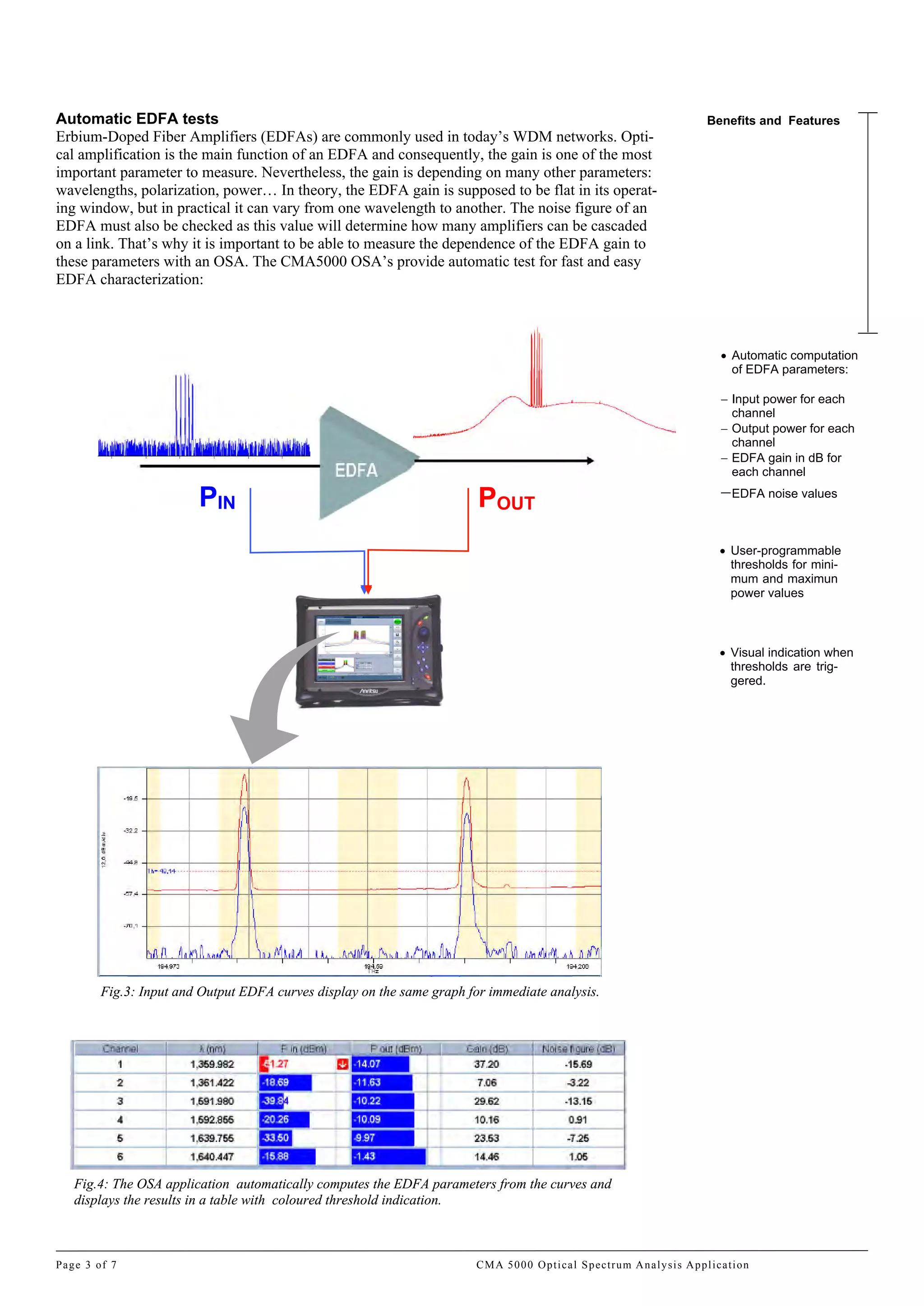
Техническое описание
осуд рственный реестр средств измерений № 45034-10
CMA5000a OSA
Оптический анализатор спектра
Серия модулей
« » www.radar1.ruСтраница 1/16
Ideal Solution For Any Test
Scenario
As a part of the CMA 5000
platform, the OSA applications
are just one other way to ac-
celerate the deployment of
services while reducing the
cost of measurement. With
test and measurement options
ranging from OTDR, connector
inspection and dispersion to
optical spectral analysis, bit
error rate, SONET/SDH analy-
sis and Gigabit Ethernet, the
CMA 5000 is the ideal single
solution for all your testing
needs.
Today’s competitive environment demands
that networks offer exceptional performance
and reliability with minimal down time. When
characterizing and documenting such strin-
gent performance levels, the CMA 5000 Opti-
cal Spectrum Analysis (OSA) applications are
the ideal single solution for facilitating accu-
rate and efficient channel management, power
balancing and tuning throughout the network.
The OSA applications lower CWDM and
DWDM installation and maintenance costs by
providing industry leading spectral analysis of
system critical parameters.
Operating from 1250 to 1650 nm, these OSA
modules for the CMA5000 are the perfect
tools for testing large wavelength range
CWDM system.
Two different modules are available to meet
all test requirements: the OSA 425 and the
OSA 400.
OSA 425: the optimized cost OSA.
This OSA is ready for field operation and
harsh environment. Its internal calibration
valid over all temperature range gives you
accurate power and wavelength measurement
in all conditions without any user calibration.
OSA 400: the highest performances for your
WDM system. The OSA 400 extends the per-
formances of the OSA 425 and provides lab
specifications in a rugged field module. With
best in class ORR, this OSA can compute
OSNR measurements with very high accura-
cy. The unique flat top filter can drop signal
up to 40Gb/s to do transport analysis.
Added value through performance:
• Wide spectral range for characterization
of the full telecom spectral range with a
single unit
• High wavelength and power accuracy in
all conditions
• Exclusive Channel Select option allows
user to drop a wavelength for additional
analysis for any modulation rate up to
40Gb/s (OSA 400)
• High ORR: up to 65 dBc at 50 GHz from
peak (OSA 400)
Reduced cost of measurement:
• Easy-to-use one button complete spectral
characterization
• User-defined configurations for custom
CWDM and DWDM testing
• Reduced test time through targeted appli-
cations
Specifications
птический н лиз тор спектр
CMA5000a OSA
Best in Class Optical Rejection for Accurate OSNR Measurements
Optical REJECTION Ratio (ORR) is a very important parameter for an Optical Spectrum Ana-
lyzer. This parameter gives the noise floor at a specified distance away from the center wave-
length of the channel under test (see fig.1). ORR values are generally specified either at 50 GHz,
25GHz or 12.5 GHz away from the center of the channel. High ORR values guarantee high
OSNR measurement accuracy. With its high Optical Rejection Ratio, more than 65dBc at 50
GHz from peak, the OSA400 is the perfect tool for measuring accurate OSNR on DWDM chan-
nels.
Fig.1: Two peaks at 50Ghz spacing with OSA400. OSNR measurements are no longer limited by
the OSA optical response.
Excellent Polarization Dependant Loss (PDL)
The polarization sensitivity of an optical spectrum analyzer is a measurement of the power
response fluctuation due to the input signal state of polarization. PDL is the ratio between the
transmittances in the best and worst polarization states. The results is expressed in dB. This pa-
rameter can strongly impact the accuracy of the power measurement: for a same level of input
power, an OSA displays different results depending on the state of polarization of the incoming
light. For field OSA, PDL is as important as power accuracy. Change of temperature, vibration
over fiber, or fiber bend will modify the polarization of light. In such a situation - frequent in the
field - the power accuracy can only be guaranteed with a minimum PDL. Here are some exam-
ples that illustrate how important the PDL value is on the power measurement accuracy (see
fig.2):
Fig.2: Influence of PDL on power accuracy measurement . With +/-0.1 dB of PDL, the
CMA 5000 OSA modules guarantee high power accuracy measurements in any conditions.
Key Features
ORR (OSA 400) :
65 dBc at ± 50 Ghz
55 dBC at ± 25 Ghz
35 dBc at ± 12.5 Ghz
Polarization Depend-
ent Loss:
± 0.1 dB (Typ)
PDL + Repeatability:
± 0.15 dB
CMA 5000 Optical Spectrum Analysis Application Page 2 of 7
> 65 dB
50 GHz
Gain Tilt: Difference in signal power
highest to lowest.
With 0.4 dB power accuracy and
0.1 PDL, the maximum error on
gain tilt measurement is 1.0 dB.
With 0.4 dB power accuracy and
0.5 PDL, the maximum error on
gain tilt measurement is 1.8 dB.
Gain Tilt
Page 3 of 7 CMA 5000 Optical Spectrum Analysis Application
Automatic EDFA tests
Erbium-Doped Fiber Amplifiers (EDFAs) are commonly used in today’s WDM networks. Opti-
cal amplification is the main function of an EDFA and consequently, the gain is one of the most
important parameter to measure. Nevertheless, the gain is depending on many other parameters:
wavelengths, polarization, power… In theory, the EDFA gain is supposed to be flat in its operat-
ing window, but in practical it can vary from one wavelength to another. The noise figure of an
EDFA must also be checked as this value will determine how many amplifiers can be cascaded
on a link. That’s why it is important to be able to measure the dependence of the EDFA gain to
these parameters with an OSA. The CMA5000 OSA’s provide automatic test for fast and easy
EDFA characterization:
Fig.3: Input and Output EDFA curves display on the same graph for immediate analysis.
Fig.4: The OSA application automatically computes the EDFA parameters from the curves and
displays the results in a table with coloured threshold indication.
Benefits and Features
Automatic computation
of EDFA parameters:
Input power for each
channel
Output power for each
channel
EDFA gain in dB for
each channel
EDFA noise values
User-programmable
thresholds for mini-
mum and maximun
power values
Visual indication when
thresholds are trig-
gered.
PIN POUT
Key Features
Unique Tunable flat
top sharp-edge filter
for channel drop
Ability to drop a signal
up to 40 Gbps for
transport analysis
User-programmable
filter width
Unique Channel Drop Filter (OSA 400 only)
The deployment of DWDM systems presents system engineers and maintenance personnel with
the added challenge of how to selectively choose one channel among many and analyze its per-
formance. For example, WDM networks are commonly used to transport SDH/SONET signal.
Each data channel is carried on its own unique wavelength. Several channels are transmitted on
the fiber at the same time. To analyze the SDH/SONET signal, it is necessary to select and drop
the corresponding wavelength. The main challenge is to ensure that the bandwidth of the filter
does not degrade the integrity of the channel under test. In the case of a 10 Gb/sec modulated
signal, depending on the modulation technique, the bandwidth of the filter within the spectrum
analyzer may need to be in excess of 20 GHz. For practical use, it is desirable that the band-
width of the filter be large enough to accommodate center wavelength drift of both the channel
under test and the measuring device, as well as the sidebands of the modulated signal. For a 40
Gb/sec system the bandwidth of the device may need to exceed 80 GHz. The OSA 400 has
unique embedded channel drop filter. Any wavelength can be selected via the tunable flat top
sharp-edge filter. The bandwidth of the filter is also adjustable depending on the modulation rate
of the signal. The OSA 400 filter can support modulation rate up to 40 Gbps. The combination
of the OSA module and the SONET/SDH module (XTA or UTA module) in the same CMA
5000 platform is particularly useful to completely test WDM links carrying SONET/SDH sig-
nals as shown below:
CMA 5000 Optical Spectrum Analysis Application Page 4 of 7
Fig.5: The CMA 5000 offers a “all-in-one” solution for extracting SDH/SONET signal from WDM
networks
Page 5 of 7 CMA 5000 Optical Spectrum Analysis Application
Notes
1 Signal from +5 to -30 dBm
from 15°C to 30°C
2 in C&L band
(1530-1610 nm)
3 User offset with external
calibration
4 in 5 consecutive scans
5 in 1 hour
6 with averaging
7 In C Band (1530-1570 nm)
8 at -15 dBm in C band
(1530-1570 nm)
9 at 1550 nm; at 23°C ±2°C
10 Typical
11 with the finest resolution
12 ±10%
13 45 nm scan
14 For FWHM > 150 pm
OSA Specifications OSA 400 OSA 425
Spectral Range 1250-1650 nm
Wavelength Accuracy 1,2 ±40 pm
±15 pm 3
Wavelength Repeatability 4 ±5 pm
Wavelength Stability 5 ±10 pm
Wavelength Linearity 2 ±15 pm
Maximum Total Safe Power +25 dBm
Power Range per
Channel 2,6 +20 to -70 dBm
Noise Floor 6,7 -75 dBm
Power Accuracy 8 ±0.4 dB
Power Repeatability 4 ±0.04 dB
Power Linearity 1 ±0.1 dB
Power Flatness 2 ±0.3 dB
Power Stability 5 ±0.1 dB
Polarization Dependent
Loss 9,10 ±0.1 dB
PDL + Repeatability 9 ±0.15 dB
Optical Resolution
Bandwidth (FWHM) 2
60 pm; 100 pm; 200 pm &
500 pm 12 <70 pm
Settings Resolution
Bandwidth
Full, 0.1 nm, 0.2 nm, 0.5 nm,
1 nm
Full, 0.1 nm, 0.2 nm, 0.5 nm,
1 nm
Optical Rejection Ratio 2,11
65 dBc at ±50 Ghz from peak
55 dBc at ±25 GHz from peak
35 dBc at ±12.5 Ghz from
peak
40 dBc at ±50 Ghz from peak
35 dBc at ±25 GHz from peak
25 dBc at ±12.5 Ghz from
peak
Optical Return Loss >45 dB >40 dB
Maximum Measurement
Time
8s (for 400 nm and 80,000 sampling points)
Scanning Time 13 < 2s
Channel Number 1024
Wavelength Readout
Resolution
1 pm
Power Readout Resolution 0,01 dB
Internal Temperature Sensor Yes
Internal Wavelength
Calibration
Yes (Automatic)
CMA 5000 Optical Spectrum Analysis Application Page 6 of 7
General Specifications
Operating Temperature 0°C to +40°C
Storage Temperature -20°C to +70°C
Humidity 95% RH non-condensing
Battery Operation Yes
Calibration Cycle 1 year recommended
Warranty 1 year standard
CMA 5000 platform features are detailed in the CMA 5000 platform specifications sheet
References Description
5510-100-OSA-XXX
OSA 400 with filter: High resolution Optical Spectrum Analyzer
covering 1250-1650 nm with channel selector for signals up to
40 Gbps
5525-000-OSA-XXX OSA 425: Optical Spectrum Analyzer covering 1250-1650nm
XXX= connector option UFC = FC/UPC
USC= SC/UPC
AFC= FC/APC
ASC= SC/APC
Ordering Guide
Channel Drop Features OSA 400 OSA 425
Spectral Range 1250-1650 nm NA
Modulation Rate Up to 40 Gbps NA
Filter Bandwidth 9 User selectable from 60 to
800 pm
NA
Insertion Loss 9 <10 dB NA
Autopositioning Accuracy 10 ±40 pm NA
Wavelength Resolution 5 pm NA
Polarization Dependent
Loss 9,10 ±0.1 dB NA
Optical Bandwidth
Resolution
20 pm NA
Flatness 14 Width at -0.2 dB> FWHM / 2 NA
Crosstalk 2 Up to 65 dB NA
Notes
2 in C&L band
(1530-1610 nm)
9 at 1550 nm; at 23°C ±2°C
10 Typical
14 For FWHM > 150 pm
16 Техническое описание ▌ MS9740A
Пожалуйста, обращайтесь:
Технические характеристики могут изменяться без дополнительного уведомления
папрffsrgsrgsrgs
, 198152, нкт- етербург
р снопутиловск я ул., д.25
ел./ф кс +7 (812) 600-48-89
ел.: +7 (812) 375-32-44
www.radar1.ru
leonid@radar1.ru
" "
фици льный предст витель и
вторизов нный сервис-центр
Anritsu Corporation

Cma5000a osa

  • 1.
    Техническое описание осуд рственныйреестр средств измерений № 45034-10 CMA5000a OSA Оптический анализатор спектра Серия модулей « » www.radar1.ruСтраница 1/16
  • 2.
    Ideal Solution ForAny Test Scenario As a part of the CMA 5000 platform, the OSA applications are just one other way to ac- celerate the deployment of services while reducing the cost of measurement. With test and measurement options ranging from OTDR, connector inspection and dispersion to optical spectral analysis, bit error rate, SONET/SDH analy- sis and Gigabit Ethernet, the CMA 5000 is the ideal single solution for all your testing needs. Today’s competitive environment demands that networks offer exceptional performance and reliability with minimal down time. When characterizing and documenting such strin- gent performance levels, the CMA 5000 Opti- cal Spectrum Analysis (OSA) applications are the ideal single solution for facilitating accu- rate and efficient channel management, power balancing and tuning throughout the network. The OSA applications lower CWDM and DWDM installation and maintenance costs by providing industry leading spectral analysis of system critical parameters. Operating from 1250 to 1650 nm, these OSA modules for the CMA5000 are the perfect tools for testing large wavelength range CWDM system. Two different modules are available to meet all test requirements: the OSA 425 and the OSA 400. OSA 425: the optimized cost OSA. This OSA is ready for field operation and harsh environment. Its internal calibration valid over all temperature range gives you accurate power and wavelength measurement in all conditions without any user calibration. OSA 400: the highest performances for your WDM system. The OSA 400 extends the per- formances of the OSA 425 and provides lab specifications in a rugged field module. With best in class ORR, this OSA can compute OSNR measurements with very high accura- cy. The unique flat top filter can drop signal up to 40Gb/s to do transport analysis. Added value through performance: • Wide spectral range for characterization of the full telecom spectral range with a single unit • High wavelength and power accuracy in all conditions • Exclusive Channel Select option allows user to drop a wavelength for additional analysis for any modulation rate up to 40Gb/s (OSA 400) • High ORR: up to 65 dBc at 50 GHz from peak (OSA 400) Reduced cost of measurement: • Easy-to-use one button complete spectral characterization • User-defined configurations for custom CWDM and DWDM testing • Reduced test time through targeted appli- cations Specifications птический н лиз тор спектр CMA5000a OSA
  • 3.
    Best in ClassOptical Rejection for Accurate OSNR Measurements Optical REJECTION Ratio (ORR) is a very important parameter for an Optical Spectrum Ana- lyzer. This parameter gives the noise floor at a specified distance away from the center wave- length of the channel under test (see fig.1). ORR values are generally specified either at 50 GHz, 25GHz or 12.5 GHz away from the center of the channel. High ORR values guarantee high OSNR measurement accuracy. With its high Optical Rejection Ratio, more than 65dBc at 50 GHz from peak, the OSA400 is the perfect tool for measuring accurate OSNR on DWDM chan- nels. Fig.1: Two peaks at 50Ghz spacing with OSA400. OSNR measurements are no longer limited by the OSA optical response. Excellent Polarization Dependant Loss (PDL) The polarization sensitivity of an optical spectrum analyzer is a measurement of the power response fluctuation due to the input signal state of polarization. PDL is the ratio between the transmittances in the best and worst polarization states. The results is expressed in dB. This pa- rameter can strongly impact the accuracy of the power measurement: for a same level of input power, an OSA displays different results depending on the state of polarization of the incoming light. For field OSA, PDL is as important as power accuracy. Change of temperature, vibration over fiber, or fiber bend will modify the polarization of light. In such a situation - frequent in the field - the power accuracy can only be guaranteed with a minimum PDL. Here are some exam- ples that illustrate how important the PDL value is on the power measurement accuracy (see fig.2): Fig.2: Influence of PDL on power accuracy measurement . With +/-0.1 dB of PDL, the CMA 5000 OSA modules guarantee high power accuracy measurements in any conditions. Key Features ORR (OSA 400) : 65 dBc at ± 50 Ghz 55 dBC at ± 25 Ghz 35 dBc at ± 12.5 Ghz Polarization Depend- ent Loss: ± 0.1 dB (Typ) PDL + Repeatability: ± 0.15 dB CMA 5000 Optical Spectrum Analysis Application Page 2 of 7 > 65 dB 50 GHz Gain Tilt: Difference in signal power highest to lowest. With 0.4 dB power accuracy and 0.1 PDL, the maximum error on gain tilt measurement is 1.0 dB. With 0.4 dB power accuracy and 0.5 PDL, the maximum error on gain tilt measurement is 1.8 dB. Gain Tilt
  • 4.
    Page 3 of7 CMA 5000 Optical Spectrum Analysis Application Automatic EDFA tests Erbium-Doped Fiber Amplifiers (EDFAs) are commonly used in today’s WDM networks. Opti- cal amplification is the main function of an EDFA and consequently, the gain is one of the most important parameter to measure. Nevertheless, the gain is depending on many other parameters: wavelengths, polarization, power… In theory, the EDFA gain is supposed to be flat in its operat- ing window, but in practical it can vary from one wavelength to another. The noise figure of an EDFA must also be checked as this value will determine how many amplifiers can be cascaded on a link. That’s why it is important to be able to measure the dependence of the EDFA gain to these parameters with an OSA. The CMA5000 OSA’s provide automatic test for fast and easy EDFA characterization: Fig.3: Input and Output EDFA curves display on the same graph for immediate analysis. Fig.4: The OSA application automatically computes the EDFA parameters from the curves and displays the results in a table with coloured threshold indication. Benefits and Features Automatic computation of EDFA parameters: Input power for each channel Output power for each channel EDFA gain in dB for each channel EDFA noise values User-programmable thresholds for mini- mum and maximun power values Visual indication when thresholds are trig- gered. PIN POUT
  • 5.
    Key Features Unique Tunableflat top sharp-edge filter for channel drop Ability to drop a signal up to 40 Gbps for transport analysis User-programmable filter width Unique Channel Drop Filter (OSA 400 only) The deployment of DWDM systems presents system engineers and maintenance personnel with the added challenge of how to selectively choose one channel among many and analyze its per- formance. For example, WDM networks are commonly used to transport SDH/SONET signal. Each data channel is carried on its own unique wavelength. Several channels are transmitted on the fiber at the same time. To analyze the SDH/SONET signal, it is necessary to select and drop the corresponding wavelength. The main challenge is to ensure that the bandwidth of the filter does not degrade the integrity of the channel under test. In the case of a 10 Gb/sec modulated signal, depending on the modulation technique, the bandwidth of the filter within the spectrum analyzer may need to be in excess of 20 GHz. For practical use, it is desirable that the band- width of the filter be large enough to accommodate center wavelength drift of both the channel under test and the measuring device, as well as the sidebands of the modulated signal. For a 40 Gb/sec system the bandwidth of the device may need to exceed 80 GHz. The OSA 400 has unique embedded channel drop filter. Any wavelength can be selected via the tunable flat top sharp-edge filter. The bandwidth of the filter is also adjustable depending on the modulation rate of the signal. The OSA 400 filter can support modulation rate up to 40 Gbps. The combination of the OSA module and the SONET/SDH module (XTA or UTA module) in the same CMA 5000 platform is particularly useful to completely test WDM links carrying SONET/SDH sig- nals as shown below: CMA 5000 Optical Spectrum Analysis Application Page 4 of 7 Fig.5: The CMA 5000 offers a “all-in-one” solution for extracting SDH/SONET signal from WDM networks
  • 6.
    Page 5 of7 CMA 5000 Optical Spectrum Analysis Application Notes 1 Signal from +5 to -30 dBm from 15°C to 30°C 2 in C&L band (1530-1610 nm) 3 User offset with external calibration 4 in 5 consecutive scans 5 in 1 hour 6 with averaging 7 In C Band (1530-1570 nm) 8 at -15 dBm in C band (1530-1570 nm) 9 at 1550 nm; at 23°C ±2°C 10 Typical 11 with the finest resolution 12 ±10% 13 45 nm scan 14 For FWHM > 150 pm OSA Specifications OSA 400 OSA 425 Spectral Range 1250-1650 nm Wavelength Accuracy 1,2 ±40 pm ±15 pm 3 Wavelength Repeatability 4 ±5 pm Wavelength Stability 5 ±10 pm Wavelength Linearity 2 ±15 pm Maximum Total Safe Power +25 dBm Power Range per Channel 2,6 +20 to -70 dBm Noise Floor 6,7 -75 dBm Power Accuracy 8 ±0.4 dB Power Repeatability 4 ±0.04 dB Power Linearity 1 ±0.1 dB Power Flatness 2 ±0.3 dB Power Stability 5 ±0.1 dB Polarization Dependent Loss 9,10 ±0.1 dB PDL + Repeatability 9 ±0.15 dB Optical Resolution Bandwidth (FWHM) 2 60 pm; 100 pm; 200 pm & 500 pm 12 <70 pm Settings Resolution Bandwidth Full, 0.1 nm, 0.2 nm, 0.5 nm, 1 nm Full, 0.1 nm, 0.2 nm, 0.5 nm, 1 nm Optical Rejection Ratio 2,11 65 dBc at ±50 Ghz from peak 55 dBc at ±25 GHz from peak 35 dBc at ±12.5 Ghz from peak 40 dBc at ±50 Ghz from peak 35 dBc at ±25 GHz from peak 25 dBc at ±12.5 Ghz from peak Optical Return Loss >45 dB >40 dB Maximum Measurement Time 8s (for 400 nm and 80,000 sampling points) Scanning Time 13 < 2s Channel Number 1024 Wavelength Readout Resolution 1 pm Power Readout Resolution 0,01 dB Internal Temperature Sensor Yes Internal Wavelength Calibration Yes (Automatic)
  • 7.
    CMA 5000 OpticalSpectrum Analysis Application Page 6 of 7 General Specifications Operating Temperature 0°C to +40°C Storage Temperature -20°C to +70°C Humidity 95% RH non-condensing Battery Operation Yes Calibration Cycle 1 year recommended Warranty 1 year standard CMA 5000 platform features are detailed in the CMA 5000 platform specifications sheet References Description 5510-100-OSA-XXX OSA 400 with filter: High resolution Optical Spectrum Analyzer covering 1250-1650 nm with channel selector for signals up to 40 Gbps 5525-000-OSA-XXX OSA 425: Optical Spectrum Analyzer covering 1250-1650nm XXX= connector option UFC = FC/UPC USC= SC/UPC AFC= FC/APC ASC= SC/APC Ordering Guide Channel Drop Features OSA 400 OSA 425 Spectral Range 1250-1650 nm NA Modulation Rate Up to 40 Gbps NA Filter Bandwidth 9 User selectable from 60 to 800 pm NA Insertion Loss 9 <10 dB NA Autopositioning Accuracy 10 ±40 pm NA Wavelength Resolution 5 pm NA Polarization Dependent Loss 9,10 ±0.1 dB NA Optical Bandwidth Resolution 20 pm NA Flatness 14 Width at -0.2 dB> FWHM / 2 NA Crosstalk 2 Up to 65 dB NA Notes 2 in C&L band (1530-1610 nm) 9 at 1550 nm; at 23°C ±2°C 10 Typical 14 For FWHM > 150 pm
  • 8.
    16 Техническое описание▌ MS9740A Пожалуйста, обращайтесь: Технические характеристики могут изменяться без дополнительного уведомления папрffsrgsrgsrgs , 198152, нкт- етербург р снопутиловск я ул., д.25 ел./ф кс +7 (812) 600-48-89 ел.: +7 (812) 375-32-44 www.radar1.ru leonid@radar1.ru " " фици льный предст витель и вторизов нный сервис-центр Anritsu Corporation