EEE341L
Introduction to CommunicationEngineering Laboratory
Software Lab Report:3
Section:02 Group No:1
Experiment no:03
Frequency Modulation & Demodulation using MATLAB Simulink
All Group members:
Sl. Name ID
1. Yasir Anaf Siddique 21221073
2. Afrida Islam 2121030
3. Md.Araf Hamim-Al-Araf 21221019
4. Saadman Safayet Ullah Sajid 21221021
2.
Objective: To performthe Frequency Modulation signal Generation and Detection using Matlab Simulink.
Theoretical Background:
Frequency Modulation (FM) is a technique in which the frequency of a carrier wave is varied in proportion to
the instantaneous amplitude of the input signal (message signal), while its amplitude remains constant. The key
advantage of FM is its ability to resist noise and interference, making it widely used in radio broadcasting,
television audio, and various communication systems. The frequency deviation is directly related to the
amplitude of the message signal, and a higher deviation leads to improved signal quality but also requires more
bandwidth.Demodulation, on the other hand, is the process of recovering the original message signal from the
modulated carrier wave. In FM, this is done by detecting the changes in frequency of the modulated signal and
converting them back to amplitude variations of the message signal. MATLAB Simulink provides a graphical
environment for designing and simulating FM modulation and demodulation systems. Using Simulink, users
can visualize the entire FM process, configure the modulator and demodulator blocks, and analyze the behavior
of the system under various conditions.
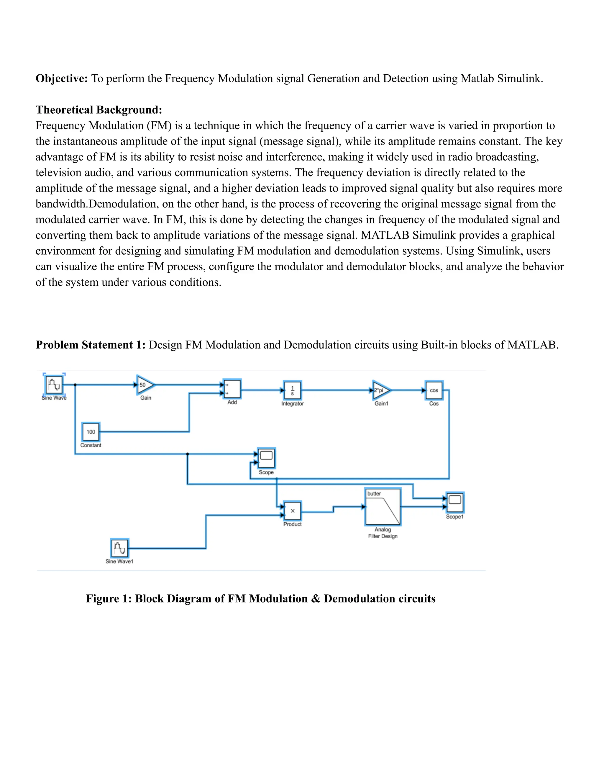
Problem Statement 1: Design FM Modulation and Demodulation circuits using Built-in blocks of MATLAB.
Figure 1: Block Diagram of FM Modulation & Demodulation circuits
3.
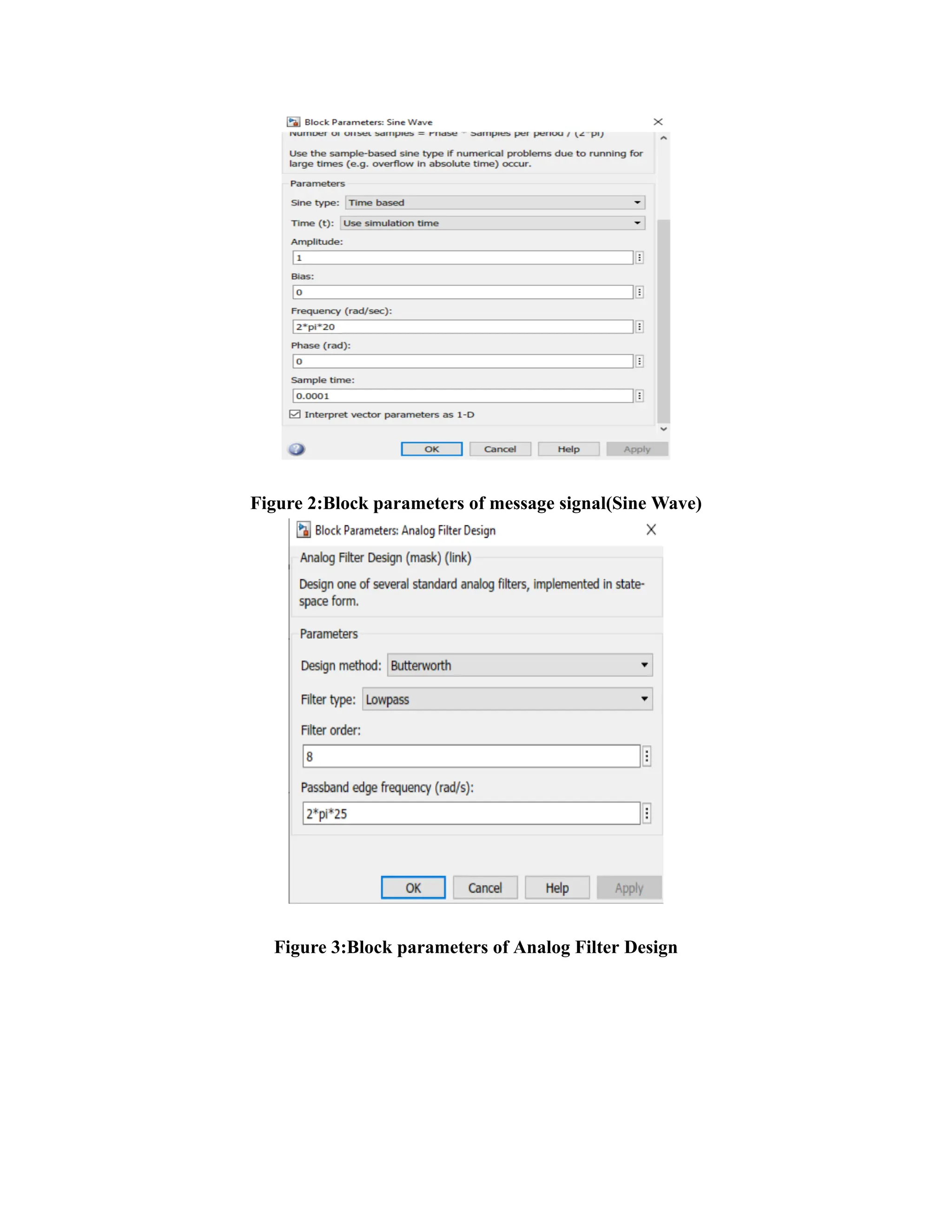
Figure 2:Block parametersof message signal(Sine Wave)
Figure 3:Block parameters of Analog Filter Design
4.
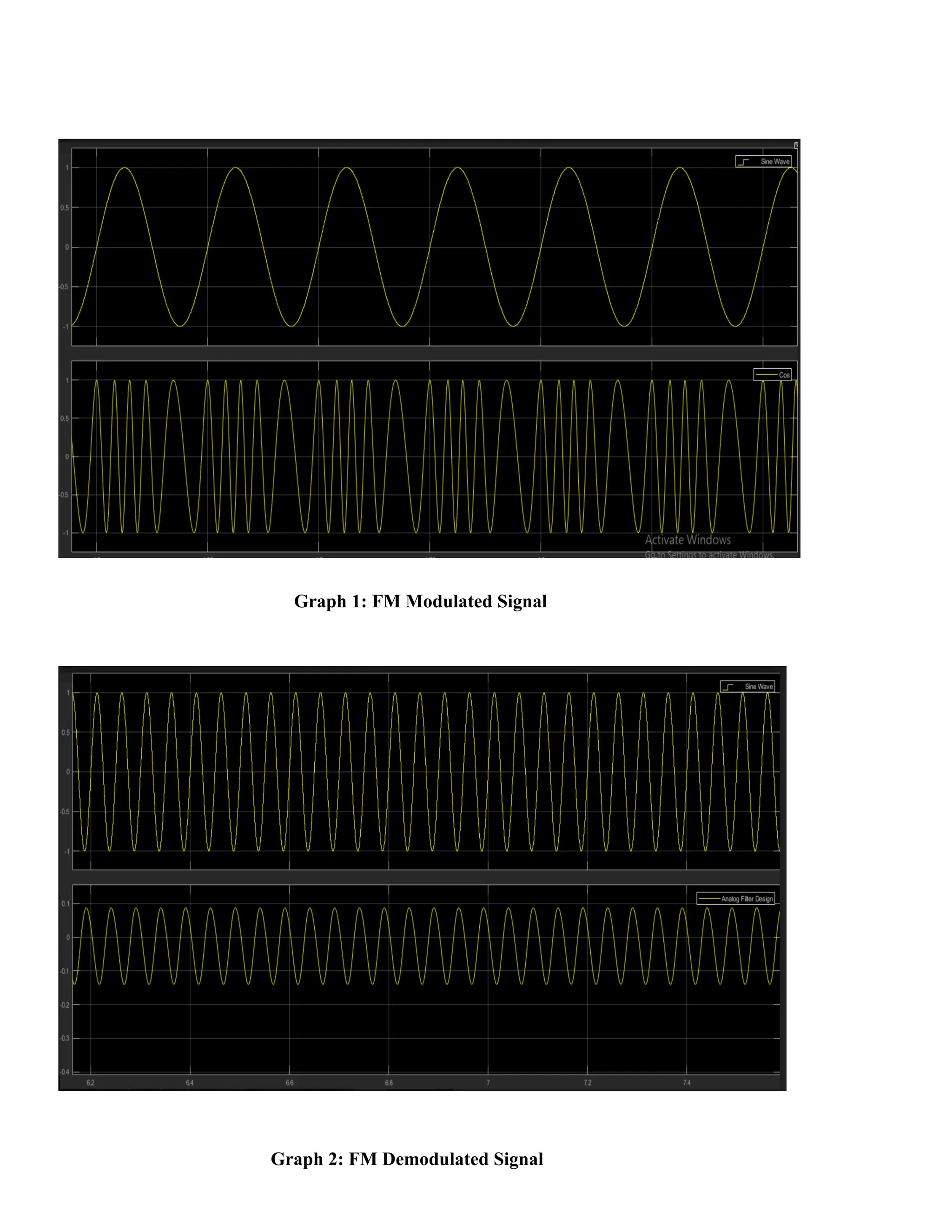
Graph 1: FMModulated Signal
Graph 2: FM Demodulated Signal
5.
Problem Statement 2:Write down a short paragraph explaining the functionalities of VCO and how the Phase
Locked Loop (PLL) method of demodulation works.
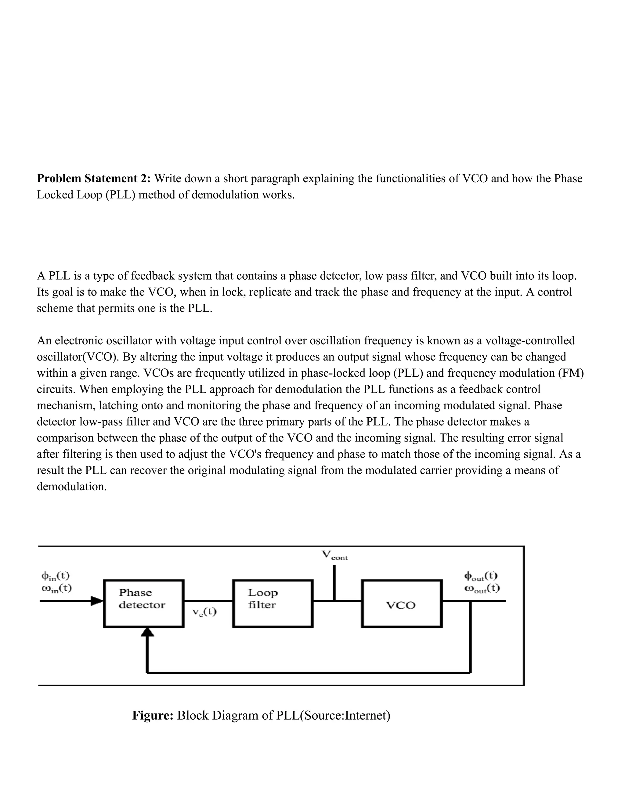
A PLL is a type of feedback system that contains a phase detector, low pass filter, and VCO built into its loop.
Its goal is to make the VCO, when in lock, replicate and track the phase and frequency at the input. A control
scheme that permits one is the PLL.
An electronic oscillator with voltage input control over oscillation frequency is known as a voltage-controlled
oscillator(VCO). By altering the input voltage it produces an output signal whose frequency can be changed
within a given range. VCOs are frequently utilized in phase-locked loop (PLL) and frequency modulation (FM)
circuits. When employing the PLL approach for demodulation the PLL functions as a feedback control
mechanism, latching onto and monitoring the phase and frequency of an incoming modulated signal. Phase
detector low-pass filter and VCO are the three primary parts of the PLL. The phase detector makes a
comparison between the phase of the output of the VCO and the incoming signal. The resulting error signal
after filtering is then used to adjust the VCO's frequency and phase to match those of the incoming signal. As a
result the PLL can recover the original modulating signal from the modulated carrier providing a means of
demodulation.
Figure: Block Diagram of PLL(Source:Internet)


![RF Module Design - [Chapter 8] Phase-Locked Loops](https://cdn.slidesharecdn.com/ss_thumbnails/rfch8-150613070348-lva1-app6892-thumbnail.jpg?width=640&height=640&fit=bounds)