This document summarizes a project to interface a USB keyboard with an Android phone. The project aims to allow writing directly on a mobile screen without the onscreen keyboard. An Arduino Mega ADK board is interfaced with a USB keyboard and AUBTM-20 Bluetooth module to pair with an Android phone and send keyboard data packets. The theory of USB protocols and human interface devices is discussed. The document provides details on Arduino code, Android app development, and programming the Arduino.

![purpose. So it finally became developing hardware which interfaces
any USB keyboard with Android mobile via Bluetooth. This will aid
in creating a more convenient way of writing on Android Phone.
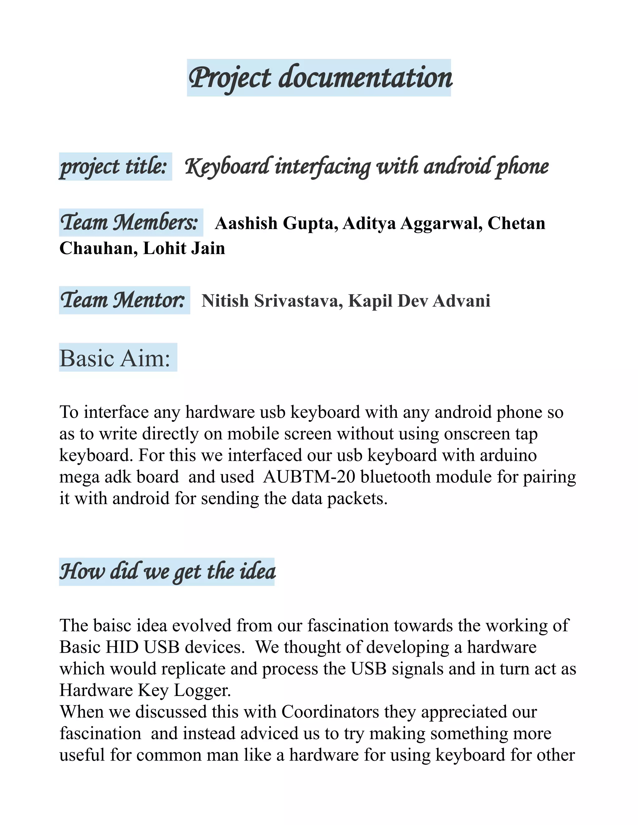
Theory
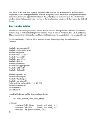
USB Protocol
USB data is sent in packets Least Significant Bit (LSB) first.
There are 4 main USB packet types :Token, Data, Handshake and Start of Frame.
Each packet is constructed from different field types, namely SYNC, PID, Address, Data, Endpoint,
CRC and EOP.
The packets are then bundled into frames to create a USB message
The USB token packet is used to access the correct address and endpoint. It is constructed with the
SYNC, PID, an 8 bit PID field, followed by a 7 bit address, followed by a 4 bit endpoint and a 5 bit
CRC.
Both the address and endpoint field must be correctly decoded for correct operation.
The data packet may be of variable length, dependent upon the data. However, the data field will be an
integral number of bytes.
Human interface
devices (HIDs)
Main article: USB human
interface device class
Joysticks, keypads, tablets and other human-interface devices are also progressively migrating from
MIDI, and PC game port connectors to USB.[citation needed] USB mice and keyboards can usually be
used with older computers that have PS/2 connectors with the aid of a small USB-to-PS/2 adapter. Such
adaptors contain no logic circuitry: the hardware in the USB keyboard or mouse is designed to detect
whether it is connected to a USB or PS/2 port, and communicate using the appropriate protocol.
Converters also exist to allow PS/2 keyboards and mice (usually one of each) to be connected to a USB
port. These devices present two HID endpoints to the system and use a microcontroller to perform
bidirectional translation of data between the two standards.[citation needed]](https://image.slidesharecdn.com/documentation-160513061935/85/Android-project-2-320.jpg)
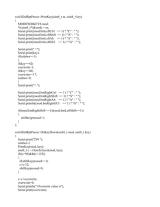
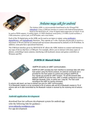
![Physical appearance
Pinouts of Standard, Mini, and Micro USB plugs. The white areas in these drawings represent hollow
spaces. As the plugs are shown here, the USB logo (with optional letter A or B) is on the top of the
overmold in all cases.[23]
Micro-B USB 3.0 compatible (cable/male end)
USB 2.0 connector on the side of the specification standard
micro USB 3.0 connector are aligned pin-minute increase in
the standard.
No.1: power (VBUS)
No.2: USB 2.0 differential pair (D−)
No.3: USB 2.0 differential pair (D+)
No.4: USB OTG ID for identifying lines
No.5: GND
No.6: USB 3.0 signal transmission line (−)
No.7: USB 3.0 signal transmission line (+)
No.8: GND
No.9: USB 3.0 signal receiving line (−)
No.10: USB 3.0 signal receiving line (+)
USB 1.x/2.0 standard pinout
Pin Name Cable color Description
1 VBUS Red +5 V
2 D− White Data −
3 D+ Green Data +
4 GND Black Ground
USB 1.x/2.0 Mini/Micro pinout
Pin Name Cable color Description
1 VBUS Red +5 V
2 D− White Data −
3 D+ Green Data +
4 ID None
Permits distinction of host connection from slave connection
* host: connected to Signal ground
* slave: not connected
5 GND Black Signal ground](https://image.slidesharecdn.com/documentation-160513061935/85/Android-project-3-320.jpg)

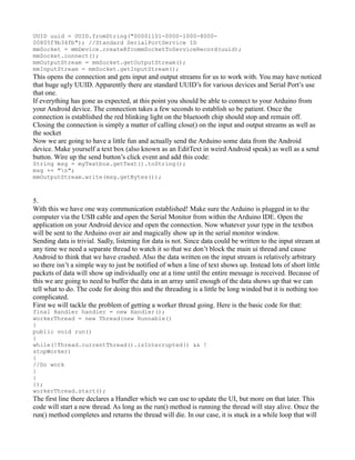
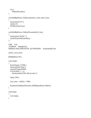
![keep it alive until our boolean stopWorker flag is set to true, or the thread is interrupted. Next lets
talk
about actually reading data.
The input stream provides an .available() method which returns us how many (if any) bytes of data
are
waiting to be read. Given that number we can make a temporary byte array and read the bytes into it
like so:
int bytesAvailable = mmInputStream.available();
if(bytesAvailable > 0)
{
byte[] packetBytes = new
byte[bytesAvailable];
mmInputStream.read(packetBytes);
}
This gives us some bytes to work with, but unfortunately this is rather unlikely to be all of the bytes we
need (or who know its might be all of them plus some more from the next command). So now we have
do that pesky buffering thing I was telling you about earlier. The read buffer is just byte array that we
can store incoming bytes in until we have them all. Since the size of message is going to vary we need
to allocate enough space in the buffer to account for the longest message we might receive. For our
purposes we are allocating 1024 spaces, but the number will need to be tailored to your specific needs.
Alright, back to the code. Once we have packet bytes we need to add them to the read buffer one at a
time until we run in to the end of line delimiter character, in our case we are using a newline character
(Ascii code 10)
for(int i=0;i<bytesAvailable;i++)
{
byte b = packetBytes[i];
if(b == delimiter)
{
byte[] encodedBytes = new byte[readBufferPosition];
System.arraycopy(readBuffer, 0, encodedBytes, 0, encodedBytes.length);
final String data = new String(encodedBytes, "US-ASCII");
readBufferPosition = 0;
//The variable data now contains our full command
}
else
{
readBuffer[readBufferPosition++] = b;
}
}
At this point we now have the full command stored in the string variable data and we can act on it
however we want. For this simple example we just want to take the string display it in on a on screen
label. Sticking the string into the label would be pretty simple except that this code is operating under a
worker thread and only the main UI thread can access the UI elements. This is where that Handler
variable is going to come in. The handler will allow us to schedule a bit of code to be executed by main
UI thread. Think of the handler as delivery boy who will take the code you wanted executed and
deliver it to main UI thread so that it can execute the code for you. Here is how you can do that:
handler.post(new Runnable()
{
public void run()
{
myLabel.setText(data);
}
});](https://image.slidesharecdn.com/documentation-160513061935/85/Android-project-7-320.jpg)