Analysis and Optimization of an Electro-Thermally and Laterally Driven Poly-Silicon Micro-Actuator
•
0 likes•293 views

A Large displacement at low voltage is generally provided by electro-thermal mechanisms. A 3-D MEMS electro-thermal micro-actuator has been designed and simulated using COMSOL Multiphysics 4.3 which is geometrically optimized to explore the effect of dimensional variation on its performance. Metallic electro-thermal actuators provide large displacements at low voltages but at the same time, the maximum temperature in the device rises very sharply due to their highly conductive nature. To overcome this problem, a semi-conductor material; poly-silicon which is compatible with IC technology is used. For further improvements in terms of displacement and temperature, the geometry of the actuator is optimized.

Recommended
Recommended
More Related Content
What's hot
What's hot (18)
Viewers also liked
Viewers also liked (20)
Similar to Analysis and Optimization of an Electro-Thermally and Laterally Driven Poly-Silicon Micro-Actuator
Similar to Analysis and Optimization of an Electro-Thermally and Laterally Driven Poly-Silicon Micro-Actuator (20)
Recently uploaded
Recently uploaded (20)
Analysis and Optimization of an Electro-Thermally and Laterally Driven Poly-Silicon Micro-Actuator
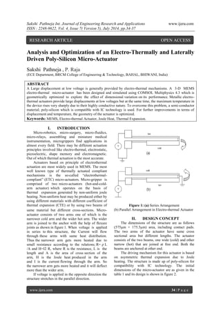
- 1. Sakshi Pathneja Int. Journal of Engineering Research and Applications www.ijera.com ISSN : 2248-9622, Vol. 4, Issue 7( Version 5), July 2014, pp.34-37 www.ijera.com 34 | P a g e Analysis and Optimization of an Electro-Thermally and Laterally Driven Poly-Silicon Micro-Actuator Sakshi Pathneja , P. Raja (ECE Department, BRCM College of Engineering & Technology, BAHAL, BHIWANI, India) ABSTRACT A Large displacement at low voltage is generally provided by electro-thermal mechanisms. A 3-D MEMS electro-thermal micro-actuator has been designed and simulated using COMSOL Multiphysics 4.3 which is geometrically optimized to explore the effect of dimensional variation on its performance. Metallic electro- thermal actuators provide large displacements at low voltages but at the same time, the maximum temperature in the device rises very sharply due to their highly conductive nature. To overcome this problem, a semi-conductor material; poly-silicon which is compatible with IC technology is used. For further improvements in terms of displacement and temperature, the geometry of the actuator is optimized. Keywords: MEMS, Electro-thermal Actuator, Joule Heat, Thermal Expansion. I. INTRODUCTION Micro-robotics, micro-surgery, micro-fluidics, micro-relays, assembling and miniature medical instrumentation, microgrippers find applications in almost every field. There may be different actuation principles involved like electro-thermal, electrostatic, piezoelectric, shape memory and electromagnetic. Out of which thermal actuation is the most accurate. Actuators based on principle of electrothermal actuation are most widely used in MEMS. The most well known type of thermally actuated compliant mechanisms is the so-called “electrothermal- compliant” (ETC) micro-actuators. Micro-gripper is comprised of two micro-actuators (hot-and-cold- arm actuator) which operates on the basis of thermal expansion generated by non-uniform joule heating. Non-uniform heat may be produced either by using different materials with different coefficient of thermal expansion (CTE) or by using two beams of same material but different cross-sections. Micro- actuator consists of two arms one of which is the narrower cold arm and the wider hot arm. The wider arm is joined to the anchor with the help of flexure joints as shown in figure 1. When voltage is applied in series to this structure, the Current will flow through these arms with same heat distribution. Thus the narrower arm gets more heated due to small resistance according to the relations; R= ρ L /A and H=I2 R, where R is the resistance, L is the length and A is the area of cross section of the arm, H is the Joule heat produced in the arm and I is the current flowing through the arm. So the narrower arm gets more heated and it will deflect more than the wider arm. If voltage is applied in the opposite direction the structure stretches in the parallel direction. Figure 1: (a) Series Arrangement (b) Parallel Arrangement in Electro-thermal Actuator II. DESIGN CONCEPT The dimensions of the structure are as follows (575μm × 175.5μm) area, including contact pads. The two arms of the actuator have same cross sectional area but different lengths. The actuator consists of the two beams, one wide (cold) and other narrow (hot) that are joined at free end. Both the beams are anchored at other end. The driving mechanism for this actuator is based on asymmetric thermal expansion due to Joule heating. The structure is made up of poly-silicon for compatibility with IC technology. The initial dimensions of the micro-actuator are as given in the table 1 and its design is shown in figure 2. RESEARCH ARTICLE OPEN ACCESS
- 2. Sakshi Pathneja Int. Journal of Engineering Research and Applications www.ijera.com ISSN : 2248-9622, Vol. 4, Issue 7( Version 5), July 2014, pp.34-37 www.ijera.com 35 | P a g e Figure 2: Design of Actuator with Dimensions Dimension Value Length of the thin (hot) arm (Lh) 500μm Width of the hot arm (Wh) 2.5μm Length of the wide (cold) arm (Lc) 440μm Width of the cold arm (Wc) 10μm Length of the flexure (Lf) 60μm Width of the flexure (Wf) 2.5μm Gap between the cold and hot arm (g) 2.5μm Anchors 75μm×75μm Table 1: Dimensions of the Microactuator III. FEM SIMULATION The software used is MEMS module of COMSOL Multi physics. The narrow arm gets more heated than the wider arm as shown in figure 3. One of the main advantages if this design is its gripping arms at room temperature. The maximum temperature lies in the middle of the hot arm i.e., 596..3K and displacement at the tip is 17.201μm at 2V as shown in figure 4. Figure 3: Total Displacement Profile Figure 4: Temperature Profile IV. GEOMETRICAL OPTIMIZATION As actuator consists of a cold arm, hot arm and flexure. There are various dimensions that can be varied to explore the effect of actuator performance in terms of tip displacement and temperature. The various dimensions varied are: 4.1 Width of the cold arm (Wc) If the width of the cold arm is increased, and the remaining dimensions remain same, the tip deflection increases. Thus wider is the cold arm, more is the tip deflection because wider cold arm means, larger cross-section area of the cold arm means less resistance, thus more current will flow trough hot arm and hence more deflection. The variation of tip displacement with the width of the cold arm is shown in Figure 5 Figure 5: Displacement versus Wc 0 2 4 6 8 10 12 14 16 18 20 0.5 1 1.5 2 Displacement(μm) Voltage (v) Wc=5 Wc=8 Wc=10
- 3. Sakshi Pathneja Int. Journal of Engineering Research and Applications www.ijera.com ISSN : 2248-9622, Vol. 4, Issue 7( Version 5), July 2014, pp.34-37 www.ijera.com 36 | P a g e width of cold arm (μm) Displacement (μm) 5 7.645 8 14.107 10 17.201 Table 2: Variation of Tip Displacement with Wc 4.2 Ratio of Cold Arm Length to Flexure Length (Lc/Lf) The variation of tip displacement as a function of ratio of length of cold arm to flexure is shown in Figure 6. It has been observed that on increasing the ratio of cold arm length to the flexure length, the tip displacement increases. The tip displacement is maximum when the Lc/Lf is 8 and then decreases slightly. It has been observed that deflection is 1.783 when Lc=500μm and when Lf=400μm, the tip displacement is 17.201μm, neither it is the minimum nor maximum rise in the temperature. So, the ratio of cold arm length to the hot arm should be optimum to achieve maximum deflection. Figure 6: Displacement versus Lc/Lf Ratio of Cold arm length to flexure length (μm) Displacement(μm) 1.66 9.5243 7.142 16.908 8.333 17.201 Table 3: Variation of Tip Displacement with Lc/Lf 4.3 Gap between the hot arm and cold arm (g) It has been described that, narrow gaps between the hot arm and cold arm leads to greater deflections. When the gap is 8μm, the deflection is 8.8415μm and when the gap is reduced to 2.5μm the deflection increases to 17.201μm. Figure 7: Tip displacement versus gap Gap between two arms (μm) Displacement (μm) 2.5 17.201 5 11.285 8 8.8415 Table 4: Variation of Tip Displacement with gap between two arms 4.4 Length of the hot arm (Lh) Deflection is highly dependent on the length of the hot arm. The deflection increases with increase in the length of the hot arm. Here, the length of the hot arm is increased from 400μm to 500μm but the ratio of Lc/Lf remains constant as 8.33. Longer hot arms leads to more deflections. Length of the hot arm (μm) Displacement (μm) 400 14.806 450 16.131 500 17.201 Table 5: variation of displacement with length of the hot arm Figure 8: Tip displacement versus Lh 0 2 4 6 8 10 12 14 16 18 Displacement (μm) Ratio of Lc/Lf (μm) 0 5 10 15 20 2.5 5 8 Tip Diplacement gap between two arms (μm) 13.5 14 14.5 15 15.5 16 16.5 17 17.5 400 450 500 Total Displacement (μm) Length of hot arm (μm) tip displacement
- 4. Sakshi Pathneja Int. Journal of Engineering Research and Applications www.ijera.com ISSN : 2248-9622, Vol. 4, Issue 7( Version 5), July 2014, pp.34-37 www.ijera.com 37 | P a g e V. CONCLUSION A 3-D electro-thermal micro-actuator has been designed using COMSOL 4.3. The results conclude that the electro-thermal actuator is highly sensitive to geometrical variations. It has been realized that longer hot arms produce more deflections but a tradeoff lies in the sense that, on increasing the length of the hot arm, resistance also increases, so there is a chance of failure due to stiction to the substrate. On decreasing the gap between the beams of the actuator, tip displacement increases. If the width of the cold arm increases, then the tip displacement also increases. The ratio of the beam length of the cold arm to the beam length of the flexure is also the important parameter which is responsible for increasing the displacement. The geometrical variation in the actuator increases the displacement at the tip significantly but the maximum temperature in the actuator is less sensitive to the geometrical variations. Thus, these designs are easy to fabricate and provides large displacements even at smaller applied voltages. VI. FUTURE SCOPE Thermal actuators are in great demand today, as these provide larger displacements at low voltages. These actuators can be used for many applications. Different materials can be used for their increased performance like polymers, as they are non conductive, these can be used for the micro-grippers in biomedical applications. The arrays of these types of actuators can be used for various applications like in switching applications, stepper motor, conveyor system, barrel lifter. VII. REFERENCES [1] V.S. Selvakumar, M.Siddhartha Goutham, M.Saravanan, S. Suganthi and L.Sujatha, 2011 “ Design and analysis of micro- tweezers with alumina as gripper using COMSOL Multiphysics” , COMSOL Conference in Bangalore. [2] Seyed Majid Karbasi, Mahnaz Shamshirsaz, Mahyar Naraghi, Mohammad Maroufi, 2010 “Optimal design analysis of electrothermally driven microactuators”, Microsyst Technol, 16:1065–1071. [3] Ang Beng Seng, Zuraini Dahari, Othman Sidek, Muhamad Azman Miskam, 2009 “ Design and Analysis of Thermal Microactuator”, European Journal of Scientific Research, ISSN 1450-216X Vol.35 No.2, pp 281-292. [4] Shamshirsaz M, Maroufi M, Asgari MB, 2008 “ Geometrical variation analysis of an electrothermally driven polysilicon microactuator”, Proc. DTIP08, Nice, France, 1:259–261. [5] R.Voicu, R.Muller, L.Eftime, 2008 “Design optimization for an Electro-thermally Actuated Polymeric Microgripper”, DTIP of MEMS & MOEMS,9-11 April. [6] Krassimir Hristov Denishev, Eleonora Zhivkova Krumova, 2005 “Thermal Micro- actuator”, ELECTRONICS Sozopol, BULGARIA, 21 – 23 September. [7] J.K.Luo, A J Flewitt, S M Spearing, N A Fleck, W I Milne, 2005 “Comparison of Micro-tweezers based on three Lateral Thermal Actuator Configurations”, Institute of Physics Publishing, J.Micromech. Microeng.15 pp 1294-1302, 10.1088/0960- 1317/15/6/022.