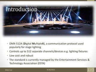
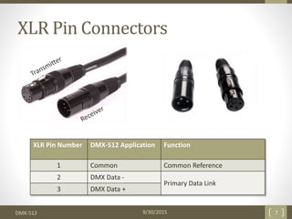
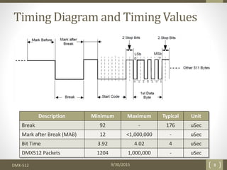
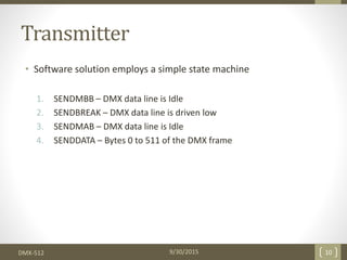
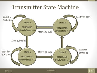
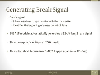
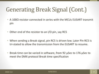
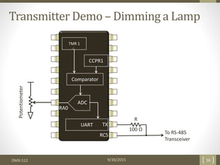
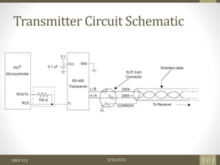
The document discusses DMX-512, a digital lighting protocol used for stage lighting that can control up to 512 channels. It evolved from analog lighting control as technology advanced. DMX-512 uses RS-485 transmission over two wires at 250kbps to transmit lighting cues from a console to multiple fixtures in a unidirectional manner without handshaking. The anatomy and timing of the protocol is explained along with demonstrations of transmitting and receiving DMX signals using PIC microcontrollers.
Optical fiber communication uses glass or plastic fibers to transmit light signals for communication over long distances. Light propagates down the fiber core through total internal reflection. Optical fibers have advantages over copper cables like higher bandwidth, lighter weight, and immunity to electromagnetic interference. There are two main types of optical fibers - single-mode fibers for long distances and multi-mode for local networks. Optical fiber communication systems have enabled modern telecommunications infrastructure.
This document provides an overview of using an OTDR (Optical Time Domain Reflectometer) to test fiber optic cabling. It discusses OTDR functionality and how to properly set up the device, including setting the range, pulse width, index of refraction, and averaging time. It also covers analyzing OTDR traces to evaluate specific events and faults along a cable span.
Designed a microwave amplifier circuit with a required bandwidth of 250MHz at a center frequency of 3.7GHz experiencing 6.5dB gain within Keysight ADS.
This document discusses optical fiber sensors, including the different types and components. It describes optical fiber sensors as sensors that measure physical quantities by modulating light intensity, spectrum, phase, or polarization as it travels through the fiber. The key types are intrinsic, where measurement occurs in the fiber, and extrinsic, where measurement is outside the fiber. Sensors can also be point-based, multiplexed, or distributed along the fiber length. Measurement methods include intensity-based and interferometric techniques. Important optical fiber components discussed are connectors, light sources, couplers, circulators, and multiplexers.
The attached narrated power point presentation is an attempt to introduce the WDM Standards framed by International Telecommunications Union as well as to familiarize oneself with the most popular WDM Components in practice. The material will be useful to KTU final year B Tech students who prepare for the subject EC 405, Optical Communications.
Este documento apresenta um resumo sobre planejamento em inteligência artificial. Aborda conceitos como agentes inteligentes, domínios de planejamento utilizando o exemplo do mundo dos blocos, e resolução de problemas de planejamento utilizando busca para frente e para trás.
Optical fiber refers to the transmission of information as light impulses along a glass or plastic wire. There are three main types of optical fiber: multimode, single mode, and photonics. Optical fiber has several advantages over metal cables, including greater bandwidth, lower power loss allowing for longer transmission distances, immunity to electromagnetic interference, lighter weight, and lower safety risks. However, optical fibers can be more fragile and expensive to install than copper cables. Optical fiber has applications in networking, high-speed data transmission, harsh environments, and various industries.
Signal Degradation In Optical Fiber
Losses in an optical fibre:-
The types of losses in a optical fibre are
Attenuation loss
Absorption
Scattering
Bending loss
Dispersion loss
Coupling loss
This circuit comprises an infrared (IR) transmitter unit and receiver unit that are mounted on opposite gate pillars. When the IR beam between the units is interrupted, a melody is triggered to sound for 30 seconds from the receiver unit to alert someone that someone is at the gate. The transmitter unit uses a 38kHz IR LED and timer to transmit the IR beam. The receiver unit uses an IR sensor and timer connected to a melody generator IC to detect the beam interruption and play the melody. The units are powered separately but connected to allow the receiver to trigger when the beam is blocked.
These slides give an extensive knowledge about the photo diode. It covers the circuit diagram and its energy band diagram. Also includes important information about noise factors and resoponsitivities.
A basic sound system consists of an input device (microphone), a control device (mixer), an amplification device (power amplifier), and an output device (loudspeaker).
The primary goal of the sound system in sound applications is to deliver clear, intelligible speech, and, usually, high-quality musical sound.
The document provides guidance on lighting design for a common room in an old age home. It recommends assuming a utilization factor of 0.6-0.9, depreciation factor of 1.2, and maintenance factor of 0.8. For the example common room of size 25m x 20m x 4m height, it selects fluorescent tubes, calculates the number of lamps needed as 120 using 350 lux, and provides a 10x6 layout with spacing between lamps. It also provides considerations and calculations for a local lighting area using 300 lux illumination level.
Optical fibers use total internal reflection to transmit light signals along their core. They have a higher refractive index core surrounded by a lower index cladding. Acceptance angle and modal/material dispersion affect signal transmission. Monomode fibers have a small single-path core to eliminate modal dispersion, while multimode fibers have a larger core allowing multiple light paths and more dispersion. Attenuation and noise also impact signal quality during fiber optic transmission.
1) The document introduces MIMO (multiple-input multiple-output) wireless communication systems and discusses their advantages over traditional SISO systems, including higher spectral efficiency and ability to benefit from multipath propagation.
2) It describes the MIMO channel model and derives the capacity of MIMO systems using singular value decomposition and water-filling principles. MIMO capacity is shown to increase approximately linearly with the number of antennas.
3) Cooperative communication techniques that enable single-antenna devices to achieve MIMO-like benefits are introduced, along with the concepts of cognitive radio networks and spectrum pooling.
Optical fiber Communication training ppthuzaifa027
The document summarizes the key steps and activities involved in an optical fiber communication training seminar pursued at Aksh Optifibre Ltd. in 2016-2017. It discusses the company profile, provides an introduction to the training, and outlines the main topics covered including the basics of optical fiber communication, fiber installation processes like trenching and blowing fiber, splicing techniques, and using equipment like OTDR for fault detection and loss measurement. The training aimed to teach technicians about optical fiber technologies and prepare them to install and maintain fiber networks.
This document describes the design and implementation of a 10-band graphic equalizer using digital signal processing techniques in MATLAB Simulink. The equalizer aims to give control over the amplitude of a sound signal at ten different resonant frequencies, tailoring the sound to a listener's preference. The design is broken down into three main stages: 1) an audio input subsystem, 2) filters and variable gain blocks at ten frequency bands, and 3) an output stage combining the filtered signals. Simulation results demonstrate the equalizer's ability to boost or cut different frequency bands, modifying the input signal's frequency spectrum. The equalizer provides a graphical user interface for adjusting the gain at each band, offering flexible control over the sound.
The document discusses Bit Interleaved Coded Modulation (BICM). It introduces BICM, which combines binary encoding, bitwise interleaving, and M-ary modulation to improve performance over fading channels compared to trellis coded modulation. It describes the system model of BICM, including the use of a binary encoder, bitwise interleaver, Gray mapping, and equivalent parallel channel model. It also discusses the information theoretical framework for analyzing BICM, including its capacity and cut-off rate.
This narrated power point presentation attempts to explain the various dispersion mechanisms that are observed in optical fibers. Some fundamental terms and concepts are also discussed. The material will be useful for KTU final year B Tech students who prepare for the subject EC 405, Optical Communications.
This document is a preface and table of contents for a set of lecture notes on mobile communication. The author has been teaching a course on mobile communication for many years at IIT Guwahati in India. The lecture notes are intended to supplement that course and provide students access to the material anytime. The notes cover introductory concepts in mobile communication as well as the evolution of mobile systems, cellular engineering fundamentals, radio wave propagation, multipath fading, and multiple access techniques. The author acknowledges the help received from students and colleagues in developing the lecture notes.
Upon completion of this chapter, students will be able to:
- Understand the key elements of a communication system including information sources, transmitters, transmission mediums, receivers, and destination equipment.
- Comprehend core concepts such as signals, modulation, noise, interference, and frequency spectrums.
- Learn about various communication system types including radio, broadcasting, and computer networks.
The document discusses the optical time domain reflectometer (OTDR), a fiber optic tester used to characterize optical fibers. It works by sending light pulses into the fiber and measuring the backscattered light. Changes in the refractive index cause Rayleigh scattering and Fresnel reflections, which the OTDR detects to measure losses and locate faults. It can determine distances along the fiber based on the time delay of reflected pulses. The OTDR is useful for measuring fiber length, attenuation coefficient, and locating faults like cuts.
This document summarizes the IR RGB LED Controller item CT305RL. It converts DMX-512 digital signals to analog signals with 1-3 output channels at 256 gradations each, maxing at 5A per channel. It can be controlled via IR remote or DMX signals for various color changing effects. Key features include DMX512 compatibility, multiple control modes, brightness and speed adjustment, and protection features. It connects an RGB LED module for controllable color lighting.
Aspects Strategiques Des Réseaux 2008 2009Eric Vyncke
The document discusses network technologies and strategic aspects of networks. It provides an introduction to networks, describes common network acronyms and standards, and discusses the impact of security, IP telephony, and virtualization on networks. The agenda outlines topics including the evolution of networks, standards organizations, and emerging technologies affecting network design.
Driver Development for applications of networking services for a WAVE based d...Janith Rukman
This document discusses driver development for IEEE 802.11p and implementation of WAVE networking services. It provides an overview of WAVE technology and its benefits. It then describes the procedures used, including developing a driver for a 5.85-5.925GHz wireless mini-PCI card in a Ubuntu environment and implementing the network on an Alix board running Voyage Linux. Implementation details are provided for the WAVE protocol stack and services. Challenges in the implementation are discussed along with budget details.
SELTA develops and markets solutions Telco Operators and Service Providers Access Networks. With its technological innovations, SELTA supports operators in the modernization of network infrastructures which are increasingly service delivery oriented with a growing demand for bandwidth
Sspi day out_2014_teledyne-paul_sandovalSSPI Brasil
This document summarizes Teledyne Paradise Datacom's Q-Net VSAT solution for providing medium to high utilization satellite communication networks. Key features highlighted include software-defined SCPC modems, fiber transceivers, HPAs, antenna systems, and integrated terminal designs. Financial analysis shows the Q-Net solution provides bandwidth savings of up to 3.6 MHz and cost savings of up to $5.1 million over 36 months compared to traditional SCPC and VSAT networks. Advanced network management capabilities are also discussed.
This document discusses Newtec's vision for shaping the future of broadcast through a multiservice approach. It outlines Newtec's Dialog platform which provides a single solution for linear and non-linear content exchanges across hybrid satellite, terrestrial and fiber networks. The platform supports various broadcast workflows and use cases including contribution, distribution and news gathering. Newtec aims to offer a future-proof solution that can adapt to new services on a shared infrastructure.
This document provides an overview of networking concepts including network components, layers of the OSI model, network structures, IP addressing, subnetting, routing, and TCP/IP protocols. Key points covered include the core, distribution, and access layers of a network hierarchy; functions of the physical, data link, network, and transport layers; MAC addressing; IP addressing classes and subnetting; TCP and port numbers; and routing protocols.
This document provides an overview of Ethernet technology, including its history and standards, hardware specifications, access methods, types of Ethernet, OSI and TCP/IP protocol layers, and connecting devices like switches, routers and firewalls. It also includes a hands-on example of network traffic between devices with different IP addresses, showing how switches, routers and firewalls direct the traffic between local and external networks.
This document provides information about networking concepts for the CCNA exam, including transmission media, network interface cards, protocols, addresses, hubs, switches, routers, and the OSI model. It defines common networking cable types and standards like Ethernet and their associated bandwidths. It also covers IP addressing schemes including public/private IP ranges, subnetting of IP classes A, B and C, and default subnet masks. Network communication methods like unicast, broadcast and multicast are defined.
In This PPT we are discussed about complete details of that product (Use,Operation, Technical details, Dimensions, Wiring, and etc..)
Please Support us and Follow our other Sites
https://automationtechplc2.blogspot.com
https://humidificationcontrol.blogspot.com
https://controlsandsystems.business.site
If you enjoyed this article, share it with your friends and colleagues
This presentation by Westermo’s Technical Lead Engineers Dakota Diehl and Benjamin Campbell, is an integral part of the Westermo webinar on March 26th 2020, covering how to get older network technology to communicate over new protocols and equipment, and bridging the gap in technologies without replacing legacy equipment. Watch it here: https://www.westermo.com/news-and-events/webinars/accessing-the-edge-with-legacy-communications
The document provides an overview of the architecture of Nexus 9000 series switches and techniques for troubleshooting them. It discusses the modular components of Nexus 9500 switches including supervisors, fabrics, I/O modules, and line cards. It also covers tools for monitoring system health and detailed troubleshooting techniques. The goal is to provide an understanding of the Nexus 9000 architecture and introduce system telemetry and troubleshooting case scenarios.
The document discusses managing Cisco IOS images and configuring WAN connections. It covers topics such as copying flash images using TFTP, resolving hostnames, password recovery, and configuring encapsulation protocols like HDLC and PPP. Specific configuration examples are provided for setting the CHAP authentication protocol on serial interfaces between two routers.
The document discusses managing Cisco IOS images and configuring WAN connections. It covers topics such as copying flash images using TFTP, resolving hostnames, password recovery, and configuring encapsulation protocols like HDLC and PPP. Examples are provided for configuring CHAP authentication between two routers connected over a serial link.
This document describes a wireless agro device control system designed to help farmers control electrical appliances on their farms wirelessly. The key components include an AT89C51 microcontroller, LAB TOOL-48UXP, MAX232 for converting voltage levels, a MOXA NPORT 5110 serial-to-ethernet converter, D-Link 2100 AP router, and solid state relays. The system allows a client computer to wirelessly control devices connected to the microcontroller via TCP/IP communication over the wireless network.
This document provides the product specification for the PX24600 high power DMX decoder and driver. The decoder can drive 6A and supports various LED lamps. It meets the DMX512/1990 standard and can decode 1 DMX channel to output an analog 0-24V signal.
The Cisco Catalyst 9120AXE-H is a Wi-Fi 6 access point for the H regulatory domain. It supports the latest wireless standards including 802.11ax, 802.11ac Wave 2, and 802.11n. The access point has dual-band 4x4:4 MIMO and a maximum throughput of 5.38Gbps. It is compatible with Cisco wireless LAN controllers and Cisco IOS XE software.
3. Introduction
• DMX-512A (Digital MultipleX), a communication protocol used
popularly for stage lighting
• Controls up to 512 separate channels/devices e.g. lighting fixtures
• Low cost and robust
• The standard is currently managed by the Entertainment Services &
Technology Association (ESTA)
DMX-512 9/30/2015 3
4. Background (Technology Evolution)
• Auto transformers
• Manual control
• Long wires
• Analog controllers with 0-10 V analog console.
• System was prone to noise
• Dimming could be non linear depending on lamps
• A separate control wire was required for each lamp
• Digital technology became cost effective
• Consoles required a new communication standard to allow different
manufacturers to use one standard
DMX-512 9/30/2015 4
6. Anatomy of the Protocol
• Unidirectional asynchronous serial transmission protocol with one
transmitter multiple receiver
• Data is transmitted at 250K baud rate using RS-485 transmission
standard over two wires and ground
• Transmitter is connected to a receiver using a 5-pin or 3-pin XLR
connector
• Protocol does not provide handshake between receiver and
transmitter or checking and correction mechanism
• So not used in safety critical application.
DMX-512 9/30/2015 6
7. XLR Pin Connectors
DMX-512 9/30/2015 7
XLR Pin Number DMX-512 Application Function
1 Common Common Reference
2 DMX Data -
Primary Data Link
3 DMX Data +
8. Timing Diagram and Timing Values
DMX-512
Description Minimum Maximum Typical Unit
Break 92 - 176 uSec
Mark after Break (MAB) 12 <1,000,000 - uSec
Bit Time 3.92 4.02 4 uSec
DMX512 Packets 1204 1,000,000 - uSec
9/30/2015 8
10. Transmitter
• Software solution employs a simple state machine
1. SENDMBB – DMX data line is Idle
2. SENDBREAK – DMX data line is driven low
3. SENDMAB – DMX data line is Idle
4. SENDDATA – Bytes 0 to 511 of the DMX frame
DMX-512 9/30/2015 10
11. Transmitter State Machine
DMX-512
SENDMBB
DmxTxState = 0
State 1
SENDDATA
DmxTxState = 3
State 4
SENDMAB
DmxTxState = 2
State 3
SENDBREAK
DmxTxState = 1
State 2
Wait for
100 uSec
Wait for
100 uSec
Wait for
100 uSec
After 100 uSec
After 100 uSec
512 bytes sent
After 100 uSec
9/30/2015 11
12. Generating Break Signal
• Break signal:
• Allows receivers to synchronize with the transmitter
• Identifies the beginning of a new packet of data
• EUSART module automatically generates a 12-bit long Break signal
• This corresponds to 48 μs at 250k baud.
• This is too short for use in a DMX512 application (min 92 uSec)
DMX-512 9/30/2015 12
13. Generating Break Signal (Cont.)
• A 100Ω resistor connected in series with the MCUs EUSART transmit
pin
• Other end of the resistor to an I/O pin, say RC5
• When sending a Break signal, pin RC5 is driven low. Later Pin RC5 is
tri-stated to allow the transmission from the EUSART to resume.
• Break time can be varied in software, from 92 μSec to 176 μSec to
meet the DMX protocol Break time specification
DMX-512 9/30/2015 13
15. Sending the Dimming Data
• The dimming data is 8-bits wide
• ‘0’ represents a light off and ‘255’ represents full intensity
• EUSART is configured for 9-bit mode and 9th bit is set to ‘1’ to
generate two stop bits
DMX-512 9/30/2015 15
16. Transmitter Demo – Dimming a Lamp
DMX-512 9/30/2015 16
CCPR1
TMR 1
ADC
Comparator
UART
To RS-485
Transceiver
100 Ω
R
TX
RC5
RA0
Potentiometer
23. PICDEM 2 Plus Board
DMX-512 9/30/2015 23
Highlights:
• Supports 18, 28 and 40-pin 8-bit devices
• Prototype development area
• Integrated input/output
connectors and components
• Connectivity to all Microchip
Programmer/Debuggers/Emulators
24. PICDEM 2 Plus Board Features
9/30/2015DMX-512 24
32 x 8 Serial (I2C) EEPROM
9 V, 100 mA AC/DC Wall
Power Supply or 9V Battery LED
(Unpopulated) Canned and
Crystal Oscillator, RC Oscillator
Potentiometer
MSLR and Input Switches
User Access for
MCU Pins
User Prototype
Area
RS232 port
for UART
25. References
• PIC18F24J10 Data sheet (DS39682): The data sheet provides all the
necessary information regarding the EUSART module, CCP module,
ADC module and electrical characteristics of the PIC microcontroller.
• PICDEM™ 2 PLUS User’s Guide (DS51275): This application note has
been tested using a pair of PICDEM 2 PLUS demo boards.
• American National Standard E1.11 – 2004: The official DMX512
protocol specifications
DMX-512 9/30/2015 25
Transmitter
State Machine
Generating a Break Signal
Circuit Schematic
Receiver
State Machine
Circuit Schematic
DMX-512A is a standard communication protocol used in theater stage lighting and fog controllers. It is used to control the dimmers, scanners, moving lights etc..
The protocol can be used to control up to 512 lighting fixtures to dim the lights, hence the number 512 in the naming convention.
A copy of the protocol specifications can be purchased from the www.esta.org or the www.ansi.org
Earlier auto transformer were used to control the light intensity
A team required to manually control the transformers
A long wire around the stage the supply the electricity
Electronic auto transformer were used later
Solved the manually operating issue resolved
But still required cumbersome wiring around the stage.
Eventually, analog controls took the place of auto-transformers, becoming quite popular, particularly the 0-10V analog consoles. Still, this system had three major drawbacks:
1. It was prone to noise.
2. Dimming could be nonlinear depending on different kinds of lamps.
3. A separate control wire was required for each lamp.
As computer technology became more cost effective, new digital consoles came to the market and with them the need for a new standard that would allow equipment from different manufacturers to interoperate.
XLR connectors are commonly used in professional audio, video and lighting applications. The connector has a rugged shell and a locking mechanism
Protocol does not provide for any form of handshake between receiver and transmitter, nor does it offer any form of error checking, or correction mechanism.
This can be a eye chart but, I put the timing diagram and values on one slide to make sure I do not have to change between slides and the audience can relate to them.
Each DMX512 transmitter sends 512 8-bit dimming values, between 0 and 255, where 0 represents the lights off and 255 represents the maximum intensity.
Each receiver connected to the DMX512 line can choose one of the 512 channels (address selection) to control its output lamp (load).
The DMX512 protocol requires the transmitter to continuously repeat (at least once a second) the transmission of a frame as shown in the timing diagram in Figure 1 and Table 2.
Figure the state machine. In this application, to simplify the code and still remain within the timing constrains, the SENDBREAK, SENDMAB and SENDMBB intervals were all set to 100 μSec. These timings can
be easily changed if required. The Timer0 module is used to control the 100 μSec timing and the spacing between the transmitted bytes.
As a demo application, we will use a potentiometer connected to the DMX512 transmitter to control remotely a lamp attached to a standard DMX512 receiver.
The PIC24J10 has a 10-bit ADC module with 13 inputs. The potentiometer can be connected to pin RA0 of the MCU corresponding to the analog input channel 0.
Since the Potentiometer won’t change very rapidly, sampling it every 10 mSec is sufficient. To generate an automatic and periodic activation of ADC, a convenient feature of the PIC18F24J10 MCU can be used. The ADC can start periodically a new conversion triggered by the CCP module.
When the compare trigger occurs (TMR1 = CCPR1), the ADC conversion starts on the pre-selected input channel and TMR1 is reset.
When ADC conversion is complete a new result is loaded into the ADRESH register and the ADIF flag is set
When the ADIF bit is detected in the main loop, the transmitter will retrieve from ADRESH the most significant 8-bits encoding the potentiometer position and will transfer them to the transmission buffer at the position corresponding to the desired channel. The same channel will be selected at the dimming receiver for demonstration.
The problem of receiving a DMX512 packet can be decomposed in three parts
The first part is the synchronization of the receiver with the beginning of a new data packet identified by a prolonged Break condition of the line. This condition can be conveniently identified by a framing error flag reported by the UART. When the line is taken to the Break level, at the beginning of a new DMX512 packet, the UART initially interprets the condition as the beginning of a new data byte. But when, after the duration of the start bit and 8 more data bits instead of the two stop bits (MARK) the line remains in the break condition, a frame error is reported. Since there is no way to predict at which point of a transmission sequence the receiver will be activated during this phase the UART is polled continuously in a loop to discard any data received until a first framing error is detected.
Once the Break condition is identified, the receiver needs to wait for the line to return to the idle state (mark) and a first byte of data to arrive. During this phase the UART is polled continuously as frame errors continue to be detected. Eventually the first byte received correctly is interpreted as the Start code. In this simple application only frames with a start code of 0 are received, frames begging with a different Start code (DMX512 extensions) are ignored.
The last part consists, once more, of a loop where the receiver captures up to 512 bytes of data and stores them sequentially in the receiver buffer. A 12-bit pointer, available in PIC18F architecture, is used to provide linear memory access to the RAM memory space.
Receiver Application Demo:
In the previous section we saw how to get the DMX512 data for 512 channels and to store them in to a receiver buffer. In this section we will use the received data to control the PWM module of a PIC microcontroller. Connecting a LED to the PWM output pin we will observe the LED brightness change in response to DMX512 dimming commands
The PIC18F24J10 Capture Compare and PWM (CCP) module offers 10-bit resolution. When used in PWM mode, it uses TMR2 as its time base and the PR2 register determines the PWM period. Since the DMX512 protocol provides only 8-bit of resolution for each channel, setting the PR2 register to 0xFF allows us to use just the 8 Most Significant Bits to control the duty cycle while still providing a PWM output frequency of approximately 16 KHz. This value greatly exceeds the minimum requirement of approximately 100 Hz. Usually considered sufficient to eliminate any visible flicker of the LED.
Since the Most Significant 8 bits of the PWM duty cycle are controlled by CCPR2L register, it is sufficient to periodically update it copying the contents of the location corresponding to the desired DMX512 address (defined by the constant CHANNEL) from inside the receiver buffer.
In the demonstration code, the CCPR2L register is updated every time a complete DMX512 frame has been received.
To test the DMX512 transmitter and receiver, a separate pair of PICDEM™ 2 PLUS demo boards was used. The PICDEM 2 PLUS can be used to demonstrate the capabilities of 18, 28 and 40-pin PIC16 and PIC18 devices. The board has a small prototyping area where the transmitter and receiver transceiver circuits can be built.
In order to take advantage of the (4) LEDs available on the board for the receiver demo, the output of the PIC18F24J10 CCP2 module can be redirected to PORTB output pin RB3 by modifying the microcontroller nonvolatile Configuration register CONFIG3H, ‘CCP2 MUX’ bit.