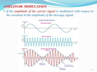
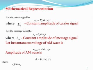
1) Amplitude modulation involves varying the amplitude of a carrier signal based on the amplitude of a message signal.
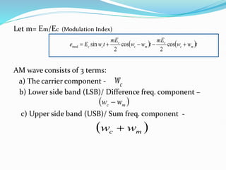
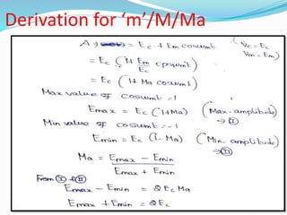
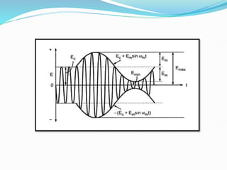
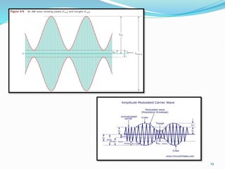
2) The mathematical representation of an amplitude modulated wave shows it consists of three components: the carrier wave, a lower sideband at the difference frequency, and an upper sideband at the sum frequency.
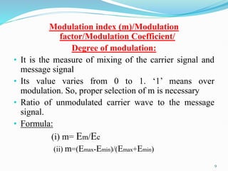
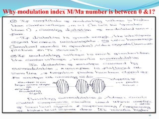
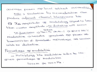
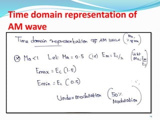
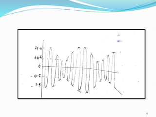
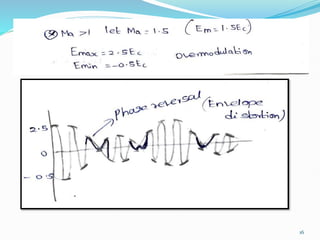
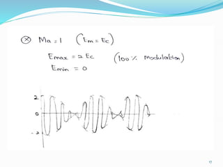
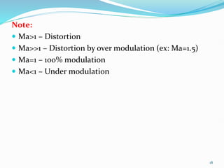
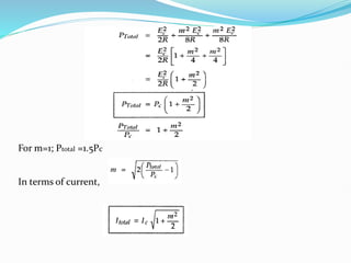
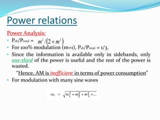
3) The modulation index, which ranges from 0 to 1, represents the ratio of the message signal amplitude to the carrier signal amplitude and determines the degree of modulation. Higher modulation indices lead to distortion.


![The output modulated signal is given by
t
w
t
w
E
E
e c
m
m
c sin
sin
mod
t
w
t
w
E
t
w
E c
m
m
c
c sin
sin
sin
t
w
w
E
t
w
w
E
t
w
E m
c
m
m
c
m
c
c
cos
2
cos
2
sin
Here SinA SinB =1/2[Cos(A-B)-Cos(A+B)]
A= ;B=
t
wm
sin t
wc
sin](https://image.slidesharecdn.com/19u405pocu12-231010234718-4ea2b80f/85/Amplitude-Modulation-6-320.jpg)