
Recommended
More Related Content
What's hot
What's hot (20)
Similar to Ac waveform and ac circuit theory of sinusoids
Similar to Ac waveform and ac circuit theory of sinusoids (20)
More from Soham Gajjar
More from Soham Gajjar (14)
Recently uploaded
Recently uploaded (20)
Ac waveform and ac circuit theory of sinusoids
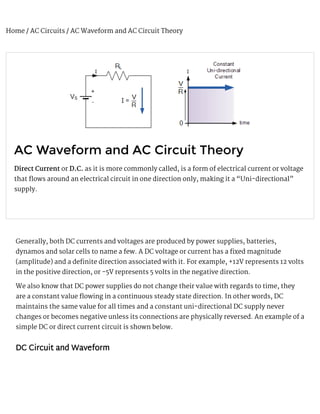
- 1. Home / AC Circuits / AC Waveform and AC Circuit Theory AC Waveform and AC Circuit Theory Direct Current or D.C. as it is more commonly called, is a form of electrical current or voltage that 漀琀ows around an electrical circuit in one direction only, making it a “Uni-directional” supply. Generally, both DC currents and voltages are produced by power supplies, batteries, dynamos and solar cells to name a few. A DC voltage or current has a 爀xed magnitude (amplitude) and a de 爀nite direction associated with it. For example, +12V represents 12 volts in the positive direction, or -5V represents 5 volts in the negative direction. We also know that DC power supplies do not change their value with regards to time, they are a constant value 漀琀owing in a continuous steady state direction. In other words, DC maintains the same value for all times and a constant uni-directional DC supply never changes or becomes negative unless its connections are physically reversed. An example of a simple DC or direct current circuit is shown below. DC Circuit and Waveform
- 2. An alternating function or AC Waveform on the other hand is de 爀ned as one that varies in both magnitude and direction in more or less an even manner with respect to time making it a “Bi-directional” waveform. An AC function can represent either a power source or a signal source with the shape of an AC waveform generally following that of a mathematical sinusoid as de 爀ned by:- A(t) = A x sin(2πƒt). The term AC or to give it its full description of Alternating Current, generally refers to a time-varying waveform with the most common of all being called a Sinusoid better known as a Sinusoidal Waveform. Sinusoidal waveforms are more generally called by their short description as Sine Waves. Sine waves are by far one of the most important types of AC waveform used in electrical engineering. The shape obtained by plotting the instantaneous ordinate values of either voltage or current against time is called an AC Waveform. An AC waveform is constantly changing its polarity every half cycle alternating between a positive maximum value and a negative maximum value respectively with regards to time with a common example of this being the domestic mains voltage supply we use in our homes. This means then that the AC Waveform is a “time-dependent signal” with the most common type of time-dependant signal being that of the Periodic Waveform. The periodic or AC waveform is the resulting product of a rotating electrical generator. Generally, the shape of any periodic waveform can be generated using a fundamental frequency and superimposing it with harmonic signals of varying frequencies and amplitudes but that’s for another tutorial. Alternating voltages and currents can not be stored in batteries or cells like direct current (DC) can, it is much easier and cheaper to generate these quantities using alternators or waveform generators when they are needed. The type and shape of an AC waveform depends upon the generator or device producing them, but all AC waveforms consist of a zero voltage line that divides the waveform into two symmetrical halves. The main characteristics of an AC Waveform are de 爀ned as: AC Waveform Characteristics max
- 3. • The Period, (T) is the length of time in seconds that the waveform takes to repeat itself from start to 爀nish. This can also be called the Periodic Time of the waveform for sine waves, or the Pulse Width for square waves. • The Frequency, (ƒ) is the number of times the waveform repeats itself within a one second time period. Frequency is the reciprocal of the time period, ( ƒ = 1/T ) with the unit of frequency being the Hertz, (Hz). • The Amplitude (A) is the magnitude or intensity of the signal waveform measured in volts or amps. In our tutorial about ,we looked at di 攀erent types of waveforms and said that “Waveforms are basically a visual representation of the variation of a voltage or current plotted to a base of time”. Generally, for AC waveforms this horizontal base line represents a zero condition of either voltage or current. Any part of an AC type waveform which lies above the horizontal zero axis represents a voltage or current 漀琀owing in one direction. Likewise, any part of the waveform which lies below the horizontal zero axis represents a voltage or current 漀琀owing in the opposite direction to the 爀rst. Generally for sinusoidal AC waveforms the shape of the waveform above the zero axis is the same as the shape below it. However, for most non-power AC signals including audio waveforms this is not always the case. The most common periodic signal waveforms that are used in Electrical and Electronic Engineering are the Sinusoidal Waveforms. However, an alternating AC waveform may not always take the shape of a smooth shape based around the trigonometric sine or cosine function. AC waveforms can also take the shape of either Complex Waves, Square Waves or Triangular Waves and these are shown below. Types of Periodic Waveform Waveforms
- 4. The time taken for an AC Waveform to complete one full pattern from its positive half to its negative half and back to its zero baseline again is called a Cycle and one complete cycle contains both a positive half-cycle and a negative half-cycle. The time taken by the waveform to complete one full cycle is called the Periodic Time of the waveform, and is given the symbol “T”. The number of complete cycles that are produced within one second (cycles/second) is called the Frequency, symbol ƒ of the alternating waveform. Frequency is measured in Hertz, ( Hz ) named after the German physicist Heinrich Hertz. Then we can see that a relationship exists between cycles (oscillations), periodic time and frequency (cycles per second), so if there are ƒ number of cycles in one second, each individual cycle must take 1/ƒ seconds to complete. Relationship Between Frequency and Periodic Time
- 5. AC Waveform Example No1 1. What will be the periodic time of a 50Hz waveform and 2. what is the frequency of an AC waveform that has a periodic time of 10mS. 1). 2). Frequency used to be expressed in “cycles per second” abbreviated to “cps”, but today it is more commonly speci 爀ed in units called “Hertz”. For a domestic mains supply the frequency will be either 50Hz or 60Hz depending upon the country and is 爀xed by the speed of rotation of the generator. But one hertz is a very small unit so pre 爀xes are used that denote the order of magnitude of the waveform at higher frequencies such as kHz, MHz and even GHz. Denition of Frequency Prexes Pre 爀x De 爀nition Written as Periodic Time Kilo Thousand kHz 1ms Mega Million MHz 1us Giga Billion GHz 1ns Terra Trillion THz 1ps Amplitude of an AC Waveform As well as knowing either the periodic time or the frequency of the alternating quantity, another important parameter of the AC waveform is Amplitude, better known as its Maximum or Peak value represented by the terms, Vmax for voltage or Imax for current.
- 6. The peak value is the greatest value of either voltage or current that the waveform reaches during each half cycle measured from the zero baseline. Unlike a DC voltage or current which has a steady state that can be measured or calculated using , an alternating quantity is constantly changing its value over time. For pure sinusoidal waveforms this peak value will always be the same for both half cycles ( +Vm = -Vm ) but for non-sinusoidal or complex waveforms the maximum peak value can be very di 攀erent for each half cycle. Sometimes, alternating waveforms are given a peak- to-peak, Vp-p value and this is simply the distance or the sum in voltage between the maximum peak value, +Vmax and the minimum peak value, -Vmax during one complete cycle. The Average Value of an AC Waveform The average or mean value of a continuous DC voltage will always be equal to its maximum peak value as a DC voltage is constant. This average value will only change if the duty cycle of the DC voltage changes. In a pure sine wave if the average value is calculated over the full cycle, the average value would be equal to zero as the positive and negative halves will cancel each other out. So the average or mean value of an AC waveform is calculated or measured over a half cycle only and this is shown below. Average Value of a Non-sinusoidal Waveform Ohm’s Law
- 7. To 爀nd the average value of the waveform we need to calculate the area underneath the waveform using the mid-ordinate rule, trapezoidal rule or the Simpson’s rule found commonly in mathematics. The approximate area under any irregular waveform can easily be found by simply using the mid-ordinate rule. The zero axis base line is divided up into any number of equal parts and in our simple example above this value was nine, ( V to V ). The more ordinate lines that are drawn the more accurate will be the 爀nal average or mean value. The average value will be the addition of all the instantaneous values added together and then divided by the total number. This is given as. Average Value of an AC Waveform Where: n equals the actual number of mid-ordinates used. For a pure sinusoidal waveform this average or mean value will always be equal to 0.637 x V and this relationship also holds true for average values of current. The RMS Value of an AC Waveform The average value of an AC waveform is NOT the same value as that for a DC waveforms average value. This is because the AC waveform is constantly changing with time and the heating e 攀ect given by the formula ( P = I .R ), will also be changing producing a positive power consumption. The equivalent average value for an alternating current system that provides the same power to the load as a DC equivalent circuit is called the “e 攀ective value”. This e 攀ective power in an alternating current system is therefore equal to: ( I .R.Average ). As power is proportional to current squared, the e 攀ective current, I will be equal to √ I squared Ave. Therefore, the e 攀ective current in an AC system is called the Root Mean Squared or R.M.S. value and RMS values are the DC equivalent values that provide the same power to the load. The e 攀ective or RMS value of an alternating current is measured in terms of the direct current value that produces the same heating e 攀ect in the same value resistance. The RMS value for any AC waveform can be found from the following modi 爀ed average value formula. RMS Value of an AC Waveform 1 9 max 2 2
- 8. Where: n equals the number of mid-ordinates. For a pure sinusoidal waveform this e 攀ective or R.M.S. value will always be equal to 1/ √2 x V which is equal to 0.707 x V and this relationship holds true for RMS values of current. The RMS value for a sinusoidal waveform is always greater than the average value except for a rectangular waveform. In this case the heating e 攀ect remains constant so the average and the RMS values will be the same. One 爀nal comment about R.M.S. values. Most multimeters, either digital or analogue unless otherwise stated only measure the R.M.S. values of voltage and current and not the average. Therefore when using a multimeter on a direct current system the reading will be equal to I = V/R and for an alternating current system the reading will be equal to Irms = Vrms/R. Also, except for average power calculations, when calculating RMS or peak voltages, only use V to 爀nd I values, or peak voltage, Vp to 爀nd peak current, Ip values. Do not mix the two together average, RMS or peak values as they are completely di 攀erent and your results will be incorrect. Form Factor and Crest Factor Although little used these days, both Form Factor and Crest Factor can be used to give information about the actual shape of the AC waveform. Form Factor is the ratio between the average value and the RMS value and is given as. For a pure sinusoidal waveform the Form Factor will always be equal to 1.11. Crest Factor is the ratio between the R.M.S. value and the Peak value of the waveform and is given as. For a pure sinusoidal waveform the Crest Factor will always be equal to 1.414. max max RMS RMS
- 9. AC Waveform Example No2 A sinusoidal alternating current of 6 amps is 漀琀owing through a resistance of 40Ω. Calculate the average voltage and the peak voltage of the supply. The R.M.S. Voltage value is calculated as: The Average Voltage value is calculated as: The Peak Voltage value is calculated as: The use and calculation of Average, R.M.S, Form factor and Crest Factor can also be use with any type of periodic waveform including Triangular, Square, Sawtoothed or any other irregular or complex voltage/current waveform shape. Conversion between the various sinusoidal values can sometimes be confusing so the following table gives a convenient way of converting one sine wave value to another. Sinusoidal Waveform Conversion Table Convert From Multipy By Or By To Get Value Peak 2 (√2) Peak-to-Peak Peak-to-Peak 0.5 1/2 Peak Peak 0.7071 1/(√2) RMS 2
- 10. Peak 0.637 2/π Average Average 1.570 π/2 Peak Average 1.111 π/(2√2) RMS RMS 1.414 √2 Peak RMS 0.901 (2√2)/π Average In the next tutorial about we will look at the principal of generating a sinusoidal AC waveform (a sinusoid) along with its angular velocity representation. Sinusoidal Waveforms 58 Comments Join the conversation! SUBMIT Your Name Email Address Write your comment here
- 11. R a c D Rstna singh What is the conclusion of where the frequency and maximum value of voltage of ac sine value takes place? alabhaya tandon thanks for clearing most my doubts how ever I still have one more doubt . if the amplitude of ac is always varying , is the frequency �xed ? Wayne Storr While the amplitude of an AC waveform varies as the alternator rotates within a magnetic �eld. The frequency is �xed as it relates to the alternators rotational speed. cengineer123 thanks for this.it was great. you help me to understand better and I try it in circuits cloud it is a very good website. Debbie One of the best and easiest to understand explanations I’ve come across. Thank you Posted on September 14th 2016 | 3:28 am Reply Posted on August 29th 2016 | 5:12 pm Reply Posted on August 29th 2016 | 6:31 pm Reply Posted on August 18th 2016 | 9:31 am Reply
- 12. X g g R D Xysa Thanks for this! gunasekhar good gopikkannankt thankyou your kind e ┃ort….. Richard Comerford You’re welcome Diode1996 Nice ever! Posted on June 01st 2016 | 12:27 pm Reply Posted on April 12th 2016 | 5:33 am Reply Posted on April 02nd 2016 | 12:49 pm Reply Posted on March 14th 2016 | 8:55 pm Reply Posted on March 25th 2016 | 5:09 pm Reply
- 13. P S View More Pradeep Very Nice Post. Can you show me how increase e 漄cency of DC-DC converter SG3525 and reduce temparature on each MOSFET? I think that i should forced turn o ┃ MOSFET with negative voltage? But i havent konwn yet what i should do? Plz help me. Also Visit My Website Click Here Saumya What does it mean when “one half cycle of p.d.” Posted on February 28th 2016 | 6:27 pm Reply Posted on February 11th 2016 | 8:58 am Reply Posted on January 21st 2016 | 1:12 am Reply THE BASICS Contact Us Privacy Policy Terms of Use Feedback FOR ADVERTISERS
- 14. Contact Sales ASPENCORE NETWORK ElectroSchematics Electronics Tutorials Electronic Products Embedded Developer ICC Media Elektroda EEWeb Mikrocontroller Engineers Garage EEM CONNECT WITH US Facebook Google+ All contents are Copyright © 2016 by AspenCore, Inc. All Rights Reserved.