Download as PDF, PPTX


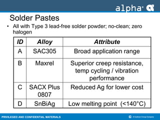
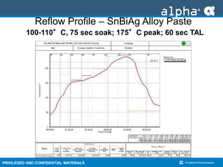
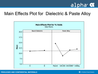
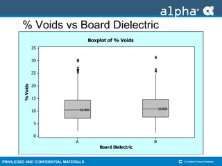
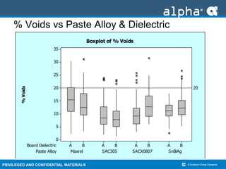
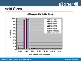
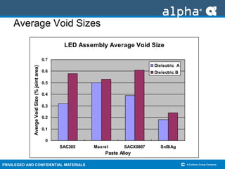
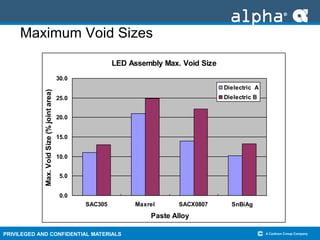
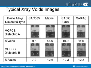


The document evaluates four different lead-free solder paste alloys for assembling LED packages onto metal core printed circuit boards with different dielectric materials, finding that the solder alloy had a more significant impact on resulting solder joint void levels than the dielectric type, with the SnBiAg alloy paste and type A dielectric board combination yielding the smallest average and maximum void sizes.


