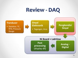
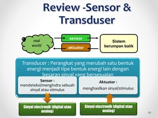
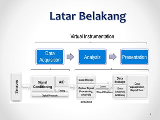
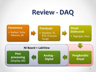
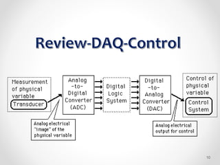
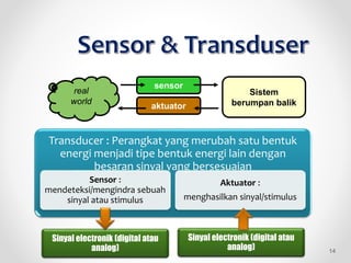
This document discusses data acquisition systems for process measurement applications. It begins by explaining the basic architecture of a data acquisition system, including sensors, transducers, signal conditioning, analog-to-digital conversion, and software for post-processing. It then focuses on the National Instruments DAQ hardware and LabVIEW software platform, highlighting features such as plug-and-play connectivity, built-in signal conditioning modules, and high-speed data streaming. The document aims to help readers understand data acquisition system design and apply techniques for signal conditioning, analog and digital data acquisition, and utilizing NI hardware configuration features for data acquisition applications.


![TYPE METAL [V/oC] RANGE [OC]
B Platinum 6 % Rhodium –
Platinum 30 % Rhodium
6 0 to 1820
E Nickel – Constantan 58.5 -270 to 1000
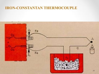
J Iron – Constntan 50.2 -210 to 760
K Nickel 10 % Cr – Nickel 39.4 -270 to 1372
N (AWG 14) Nicrosil – Nisil 39 0 to 1300
N (AWG 28) Nicrosil – Nisil 26.2 -270 to 400
R Platinum 13 % Rhodium –
Platinum
11.5 -50 to 1768
S Platinum 10% Rhodium –
Platinum
10.3 -50 to 1768
T Copper - Constantan 38 -270 to 400
W-Re Tungsten 5 % Rhodium –
Tungsten 26 % Rhodium
19.5 0 to 2320
22](https://image.slidesharecdn.com/akuisisidata-220716014626-ee8b95e6/85/Akuisisi-data-pptx-22-320.jpg)