This document provides an overview of point, line, and plane defects in materials, as well as intrinsic and extrinsic defects. It discusses various types of intrinsic defects like vacancies, self-interstitials, Schottky defects, and Frenkel defects. Extrinsic defects covered include substitutional/interstitial impurities, aliovalent impurities, and charge compensation defects. Non-stoichiometry and color centers are also introduced. Examples are provided to illustrate different types of defects and how they impact properties like density and electrical conductivity. The document is intended as a study aid for students learning about the chemistry of materials.

![3
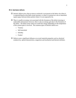
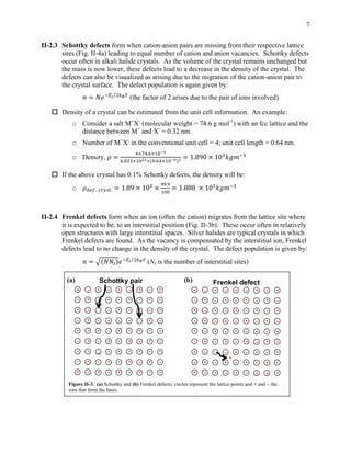
II-1. Point, line and plane defects
Ideal crystal structures discussed in Sec. I exist rarely; often there are defects in the
structure, which can occur in different ways. The defects often influence the materials
properties significantly, and hence are important targets for exploration.
The term, point, line and plane defects indicates clearly the region over which a defect
(absence of the atom/molecule expected based on the bulk structure, or presence of a
wrong atom/molecule) exists – a lattice site or interstitial point, a whole row of lattice
sites or a plane formed by a 2-D array of lattice points.
Plane defect: Typical examples are small angle grain boundaries and stacking faults (Fig.
II-1).
Line defect: The most common are edge and screw dislocations (Fig. II-2). The defect
propagates parallel to the direction of the slip of the lattice planes in an edge dislocation;
the defect propagation is perpendicular to the slip direction in a screw dislocation.
Presence of a defect is shown by a mismatch (Burger’s vector) if one follows equal
number of unit cell vectors in opposite directions to make a circuit around the defect area.
Figure II-2. Schematic drawing of (a) edge and (b) screw dislocation [Source:
http://inspirehep.net/record/1094489/plots].
Burger’s vector
(a)
Direction of slip = Direction of defect
propagation
(b)
Direction of slip Direction of defect
propagation
Figure II-1. Plane defects : (a) small angle grain boundary, (b) stacking fault in a hexagonal close packing (hcp)
sequence contrasted with defect-free hcp and ccp.
(a) hcp …. A B A B A B A B A B A B ….
ccp …. A B C A B C A B C A B C ….
defect hcp …. A B A B B A B A B A B A ….
defect location
(b)](https://image.slidesharecdn.com/aiidefectsnonstoichiometry-220408132349/85/A_II_Defects_Nonstoichiometry-pdf-3-320.jpg)
![11
II-4.1 Classifications
Common examples of non-stoichiometry may be found in metal oxides.
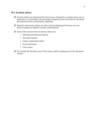
Consider a metal compound with the stoichiometric composition, MX. During its
formation, if the partial pressure of X (eg. oxygen) is maintained higher or lower than the
equilibrium value required to form the stoichiometric composition (𝑝𝑋2
(𝑥) > 𝑝𝑋2
(0) or
𝑝𝑋2
(𝑥) < 𝑝𝑋2
(0) respectively) one could end up with non-stoichiometric oxides.
The following represent the typical situations that follow. The equations represent the
origin of the non-stoichiometric system (I and L represent the interstitial and lattice sites
respectively); the figures show the defect formation. M+
and X-
represent metal cations
and their counter anions; the actual ions may have charges different from +1 and -1.
The case of 𝑝𝑋2
(𝑥) > 𝑝𝑋2
(0):
o MX1+x:
1
2
𝑋2 + 𝑒−
→ 𝑋− (𝐼); 𝑀+
→ 𝑀2+
+ 𝑒− (𝐿)
Example: 𝑈𝑂2 +
𝑥
2
𝑂2
1150𝑜𝐶
→ 𝑈𝑂2+𝑥 [0 < 𝑥 < 0.25].
U4+
is partially oxidized, and O2-
formed at the interstitial sites.
o M1-xX:
1
2
𝑋2 + 𝑒−
→ 𝑋− (𝐿); 𝑀+
→ 𝑀2+
+ 𝑒− (𝐿)
Example: (1 −
𝑥
2
) 𝐶𝑢2𝑂 + (
𝑥
4
) 𝑂2 → 𝐶𝑢2−𝑥𝑂
Cu+
is partially oxidized, and vacancies appear at Cu+
sites.
X-
formed at
interstitial site
Vacancy
formed at
M+
site](https://image.slidesharecdn.com/aiidefectsnonstoichiometry-220408132349/85/A_II_Defects_Nonstoichiometry-pdf-11-320.jpg)
![12
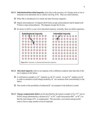
The case of 𝑝𝑋2
(𝑥) < 𝑝𝑋2
(0):
o MX1-x: 𝑋−
→
1
2
𝑋2 + 𝑒− (𝐿); 𝑀+
+ 𝑒−
→ 𝑀 (𝐿)
Example: TiO1-x
Ti2+
is partially reduced and O2-
vacancies form. Titanium oxide is known to
form a large range of non-stoichiometric compounds, TiO0.64 to TiO1.27.
o M1+xX: 𝑋−
→
1
2
𝑋2 + 𝑒− (𝐼); 𝑀+
+ 𝑒−
→ 𝑀 (𝐿)
Example: (1 + 𝑥)𝑍𝑛𝑂
∆
→ 𝑍𝑛1+𝑥𝑂 +
𝑥
2
𝑂2 ; ZnO is white and Zn1+xO yellow.
Zn2+
is partially reduced to Zn1+
[Ref.: Ceramic Materials: Science and Engineering, C. B.
Carter, M. G. Norton, Springer, 2007, p.188], and O2-
oxidized with O2 boiling out.
II-4.2 More examples of non-stoichiometric compounds are listed below with special
structural or materials attributes noted briefly.
o Several non-stoichiometric phases NiTex form between the two stoichiometric
extremes, NiTe (NiAs structure) and NiTe2 (CdI2 structure) (Fig. II-5).
Vacancy
formed at
X-
site
M+
and X-
vacancies form;
M migrates to
interstitial site
Figure II-5. NiTe [NiAs structure, Ni (red), As (blue)] and NiTe2 [CdI2 structure, Cd (red),
I (blue)]; view of the 2-D lattice of Ni (in NiAs) and Cd (in CdI2) are shown along with the
two types of lattice sites, A and B which are also marked on the 3-D structures.
A
B
A
B
A
B
A
B
A
B](https://image.slidesharecdn.com/aiidefectsnonstoichiometry-220408132349/85/A_II_Defects_Nonstoichiometry-pdf-12-320.jpg)
![13
o Praseodymium oxide has a range of non-stoichiometric compositions, PrO2-x (0 <
x < 0.25) at 1000o
C. At lower temperatures, infinitely adaptable structures with
the formula PrnO2n-2 (n = 4, 7, 9, 10, 11, 12, ) are observed. The series can be
visualized as ranging from Pr2O3 (n = 4) to PrO2 (n = ). PrO2 has the fluorite
structure with Pr forming an fcc lattice and O occupying all the Td sites (note that
a conventional unit cell with 4 atoms has 8 Td and 4 Oh sites). Pr2O3 has the C-
type rare earth M2O3 structure in which ¾ of the Td sites of the fcc lattice of Pr are
occupied by O. The O vacancies cluster to form superlattice structures.
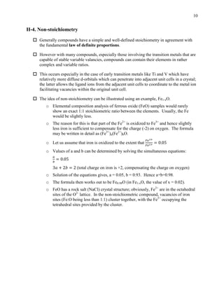
o Tungsten bronzes are derived from WO3. Insertion of alkali metals, M (Na, K, Rb
or Cs) gives rise to the non-stoichiometric systems, MxWO3. The color and
electrical properties are dependent on x. For example, in NaxWO3 the color
ranges from golden to red, orange, purple and blue-black as x varies from 0.9 to
0.3; electrical conductivity decreases with x. WO3 has an ReO3 structure (Fig. II-
6); in NaxWO3, Na sits at the body centre of the cubic unit cell with W at the
vertices and O at the edge centres. The body centre has fractional occupation, x;
when x = 1, a perovskite structure is obtained.
o The high temperature superconductors, for example, YBa2Cu3O7-x form another
important class of non-stoichiometric compounds. When x = 0.5, all copper are in
the Cu2+
state. When x decreases (ie. O content increases), holes are formed in
the Cu-O layer (equivalent to the formation of Cu3+
); when x = 0, there are two
Cu2+
and one Cu3+
. Structural transformations accompany the variation of x. The
material is superconducting only for x < 0.5.
o An interesting example of non-stoichiometry in organic solids is the charge
transfer (donor-acceptor) complex (M2P)1-x(P)xTCNQ. P = phenazine, M2P =
N,N-dimethyl phenazine (a strong -electron donor), and TCNQ =
tetracyanoquinodimethane (a strong -electron acceptor). x = 0 corresponds to
M2P+
TCNQ-
, a semi-conductor. When x 0, P occupies the sites of M2P, but
remains neutral as it is a poor donor; (M2P+
)1-x(P)xTCNQ(1-x)-
has partial ionicity
on TCNQ leading to metallic behavior.
o The bromide salt of tetrathifulvalene, TTF(Br)x is another electrically conducting
organic solid, thanks to the partial oxidation of TTF.
Figure II-6. Unit cell of WO3 [ReO3 structure, Re (blue), O (red)]; the body-centre site, A is
occupied by the alkali metal (fractional occupation, x of Na in NaxWO3).
A](https://image.slidesharecdn.com/aiidefectsnonstoichiometry-220408132349/85/A_II_Defects_Nonstoichiometry-pdf-13-320.jpg)
![14
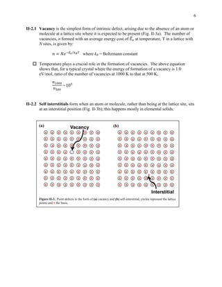
II-5. Color centres
A typical observation when crystals of alkali metal halides are heated in presence of a
metal vapor is that they acquire a color; the color depends on the crystal and not on the
type of metal vapor. The color is attributed to F-centres (farbe = color in German).
These arise due to anion vacancies (point defects) in the crystal which trap unpaired
electrons; if the energy levels of the electron confined in the vacancy site are such that
visible light of specific wavelengths can be absorbed, the crystal becomes colored.
o The phenomenon can be explained using the NaCl crystal.
NaCl + M vapor (NaCl)-
M+
[M = Na, K etc.]
o As the unit cell of the crystal becomes larger, the energy levels get closer and the
wavelength of the light absorbed increases (Table II-1, Fig. II-7).
Table II-1. Correlation between unit cell size and F-centre absorption
Crystal
Unit cell
length (Å)
Light absorption
Energy (eV) Wavelength (nm)
NaCl 5.64 2.67 464
KCl 6.29 2.20 564
RbCl 6.58 1.97 629
KBr 6.54 2.00 620
Combinations of two or three F-centres lead to defects called M and R-centres.
The unpaired electrons make the materials paramagnetic.
Figure II-7. Color due to F-centres formed in NaCl, KCl, KBr crystals. Source:
http://archive.education.mrsec.wisc.edu/background/F_center/images/NaCl_KCl_KBr.jpg](https://image.slidesharecdn.com/aiidefectsnonstoichiometry-220408132349/85/A_II_Defects_Nonstoichiometry-pdf-14-320.jpg)


