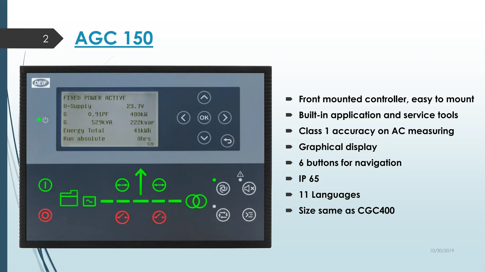
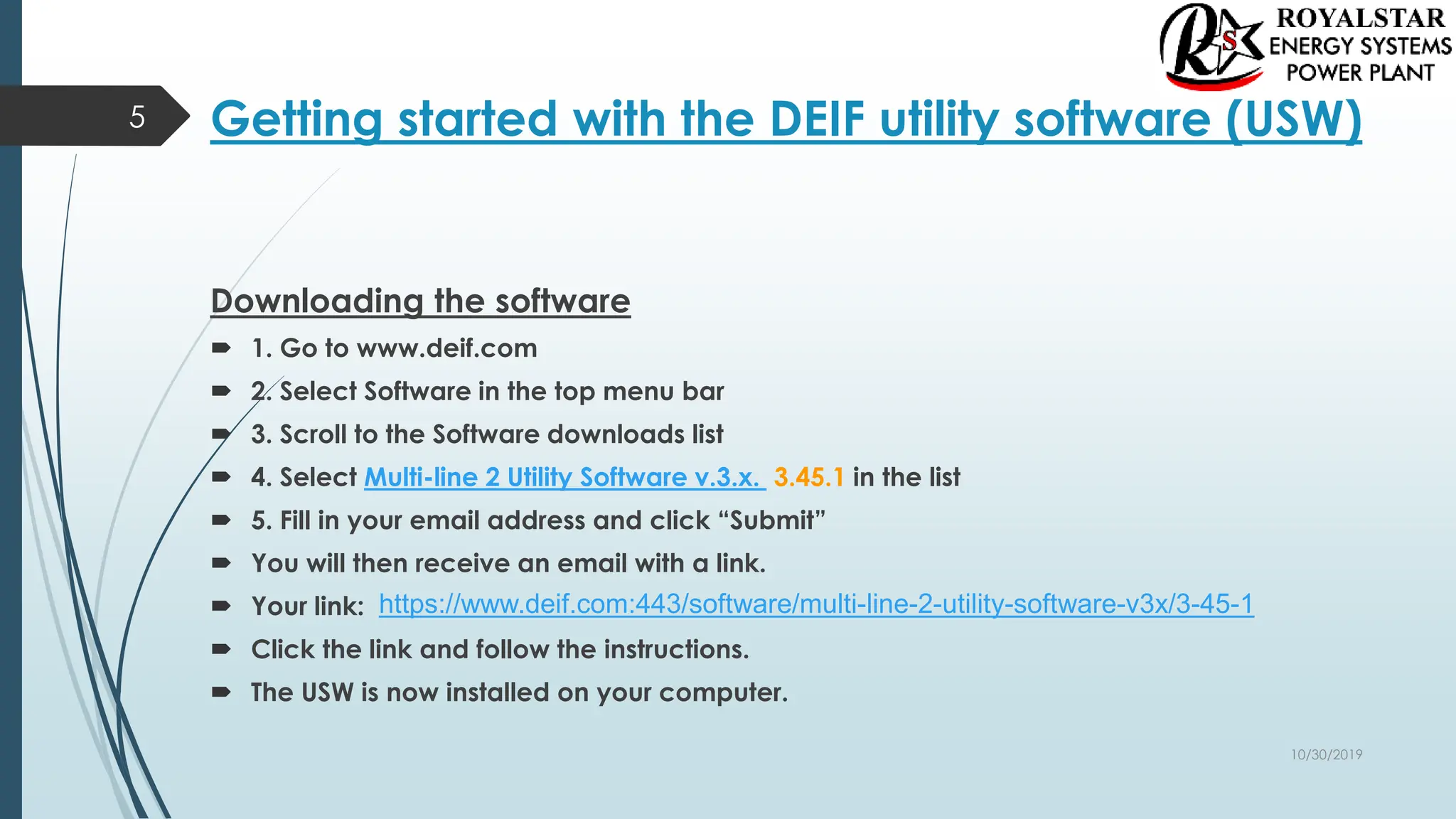
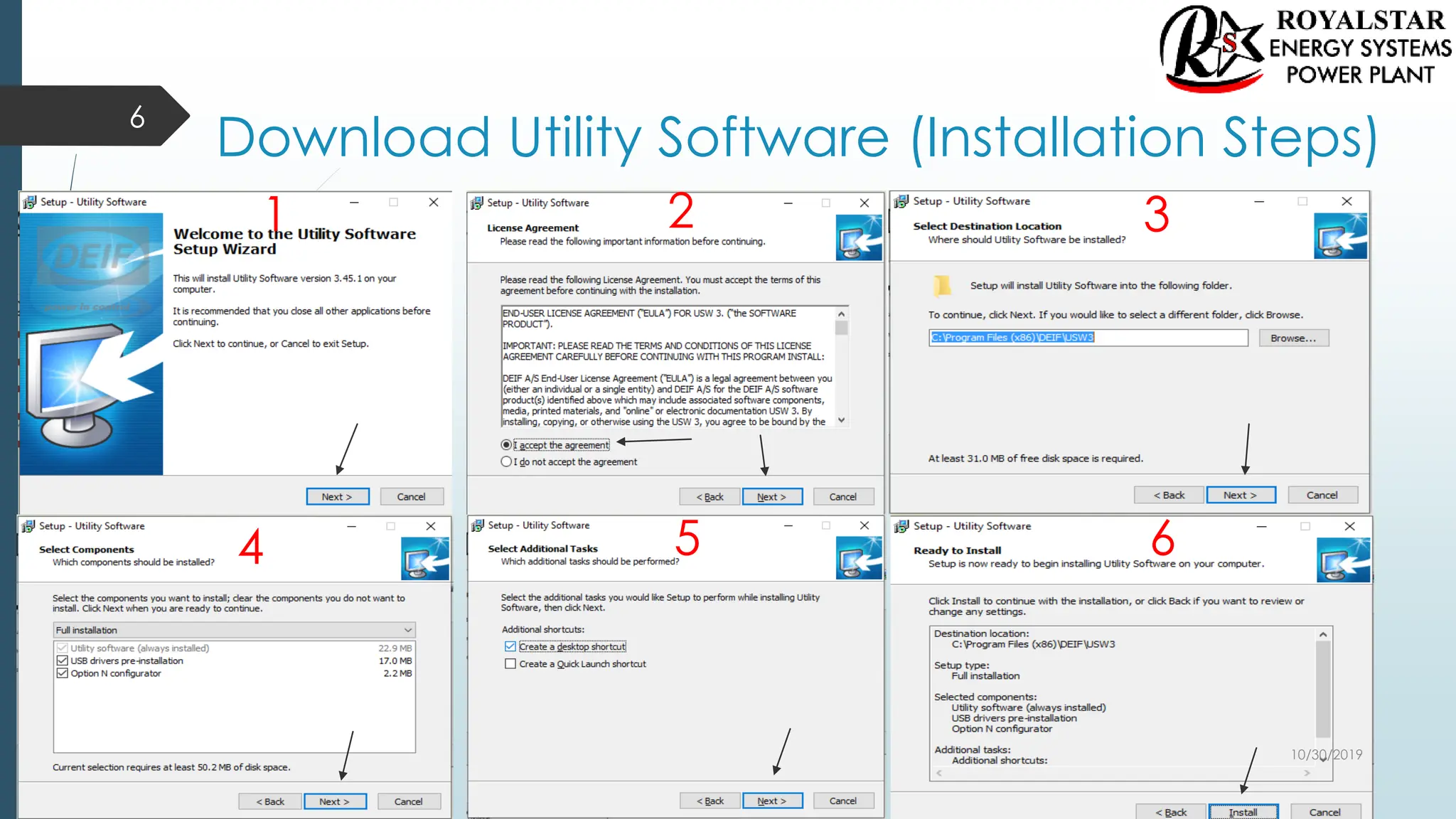
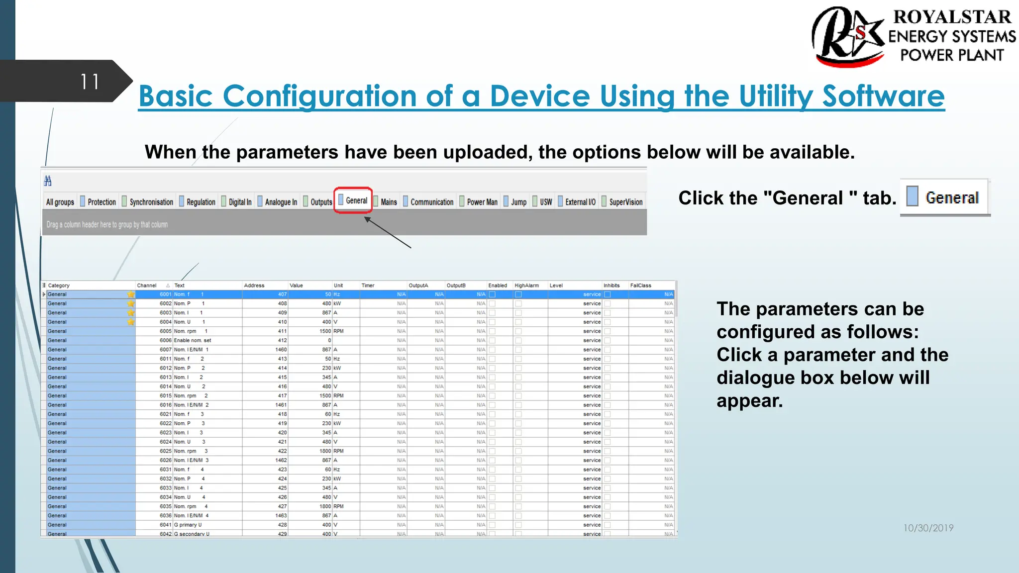
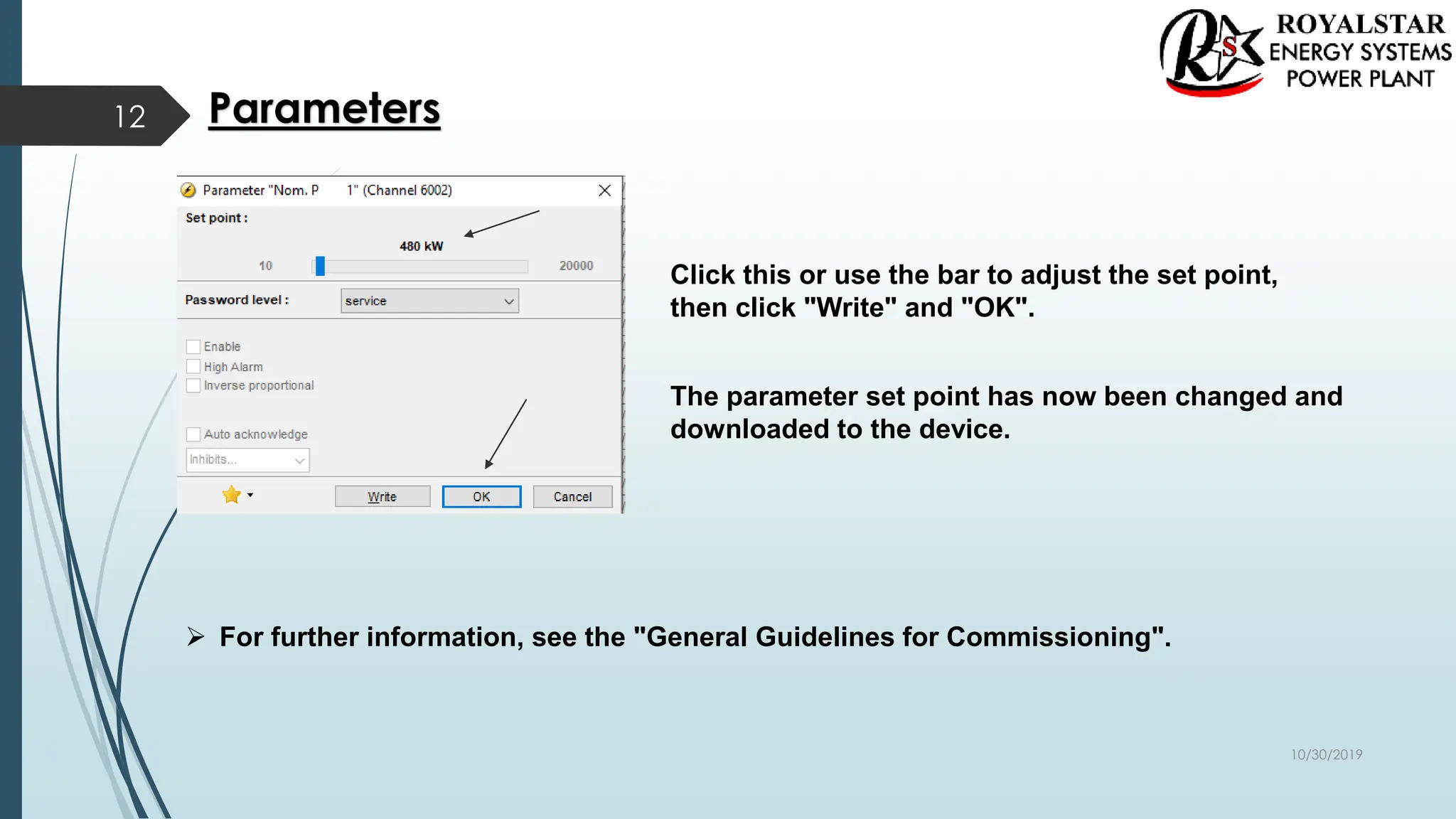
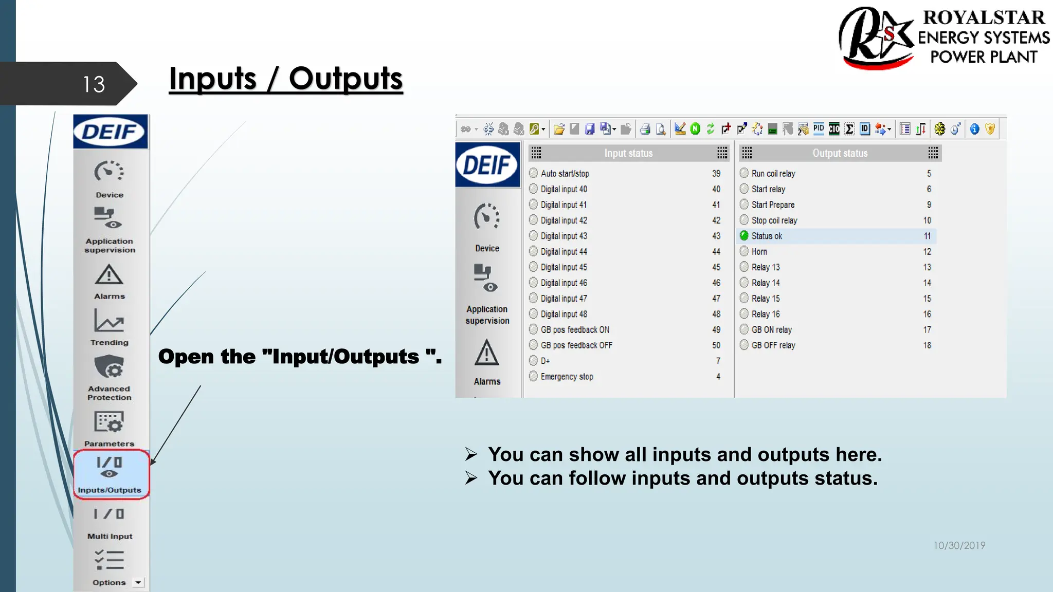
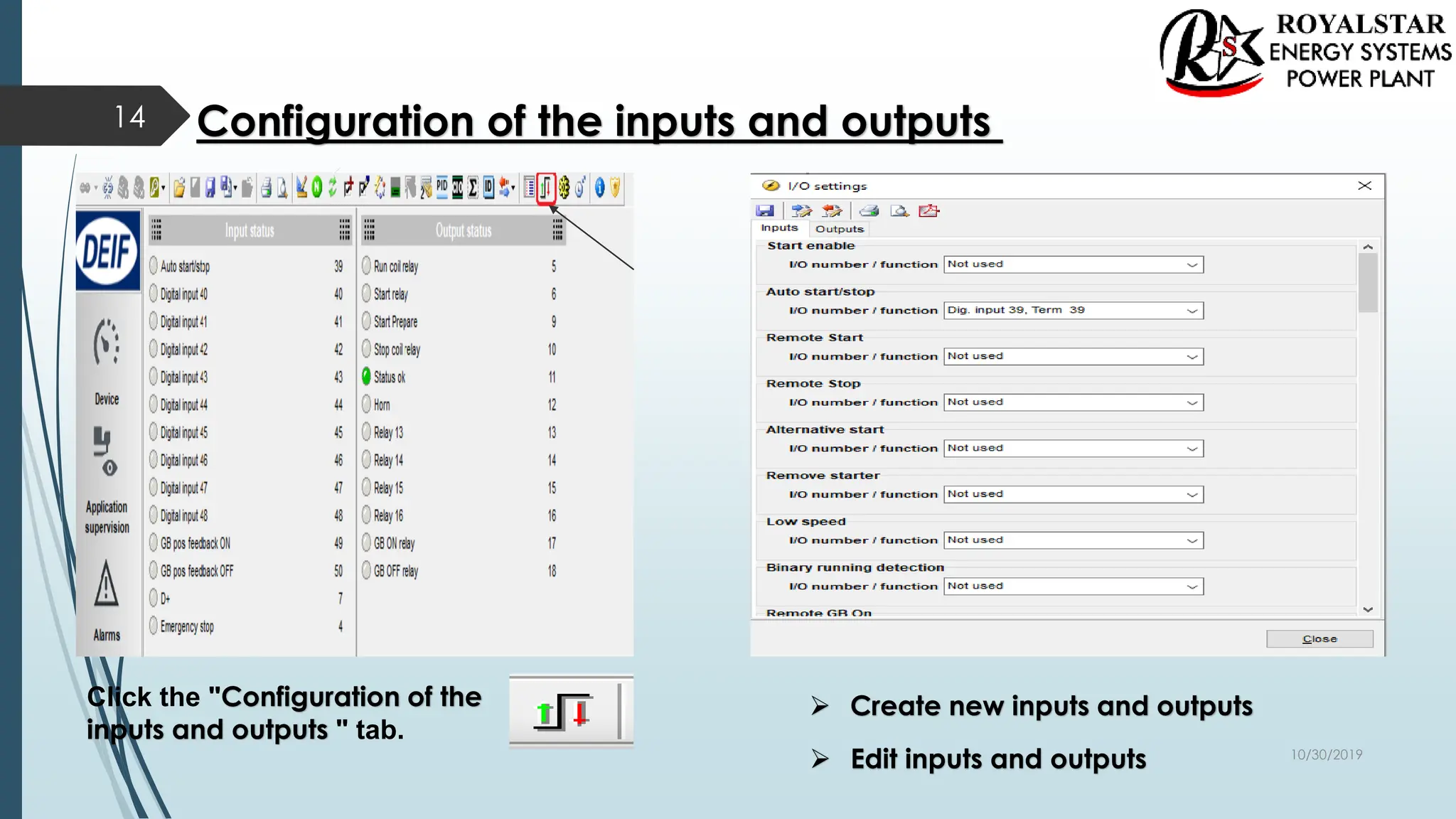
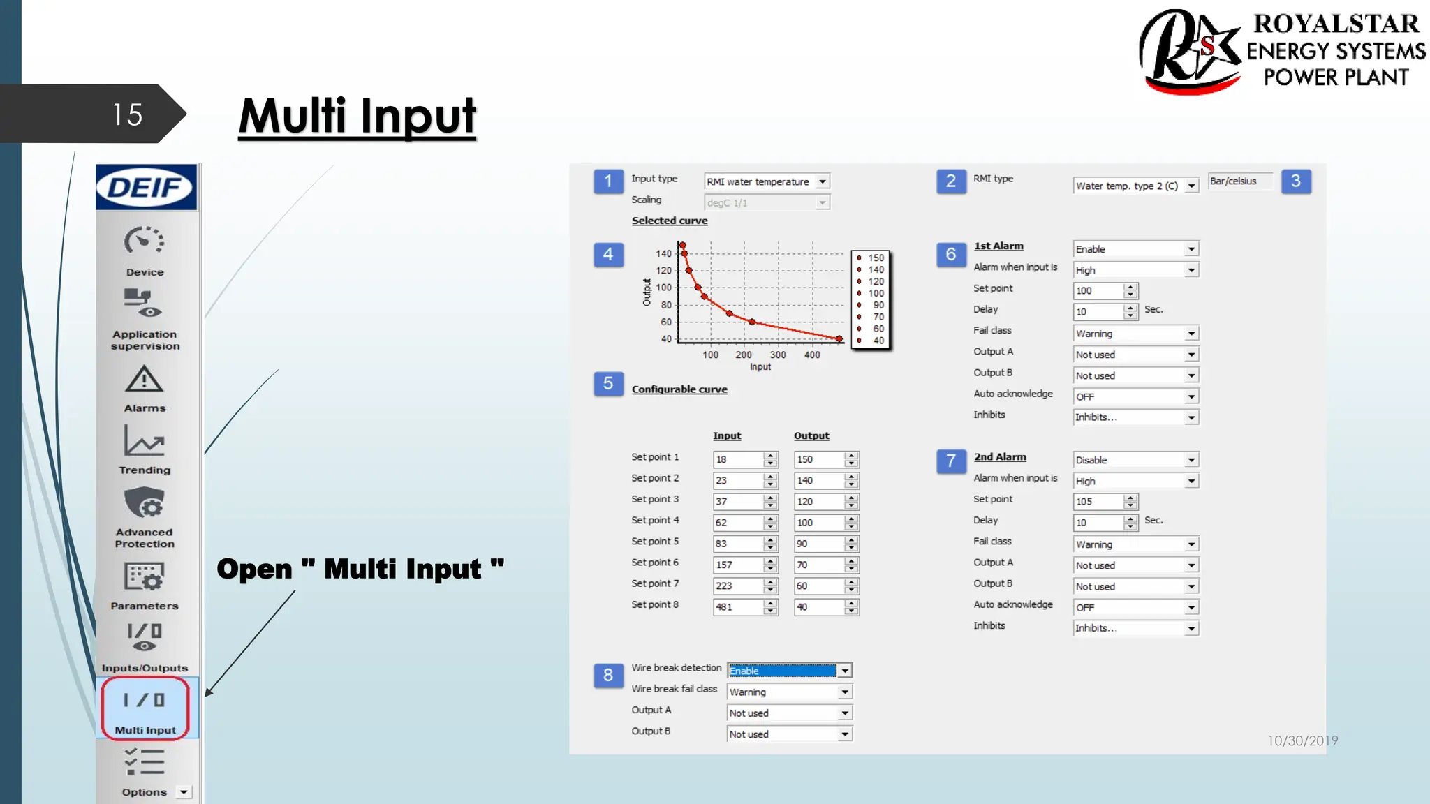
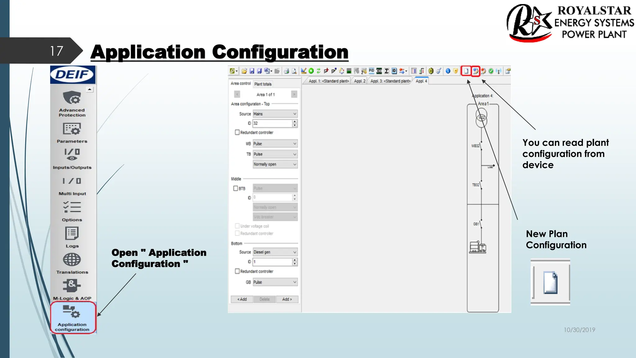
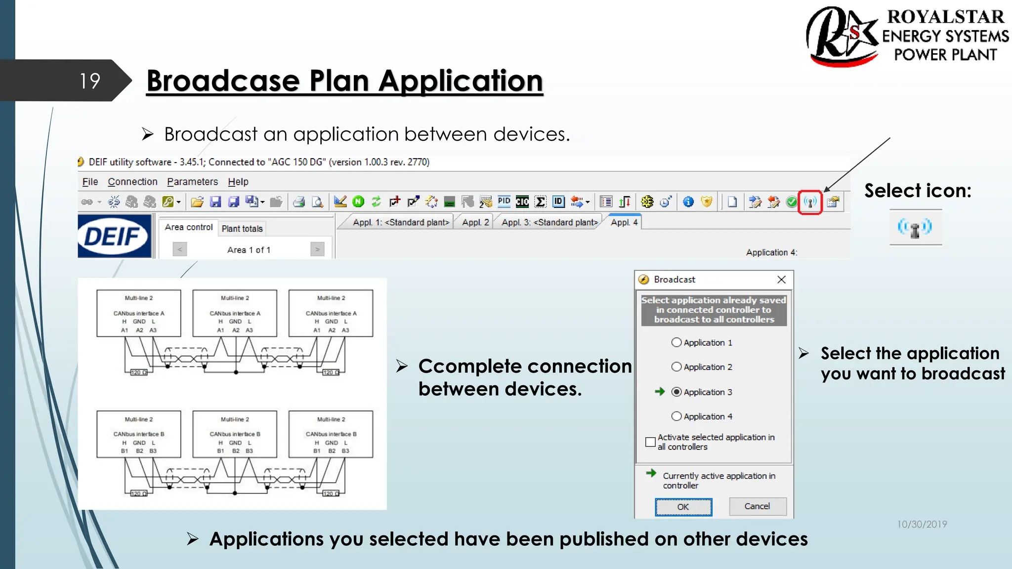
New Product AGC 150
 Newest processor technology
 Robust and compact design
1
 Graphical user interface
 32 Gensets support
10/30/2019
AGC 150
 Front mounted controller, easy to mount
 Built-in application and service tools
 Class 1 accuracy on AC measuring
 Graphical display
 6 buttons for navigation
 IP 65
 11 Languages
 Size same as CGC400
2
10/30/2019
Adapting Mimic
3
Standalone Island Standalone AMF Standalone Parallel without MB
Genset MAINS+TB MAINS BTB
10/30/2019
The First Steps
 AGC Single Application
4
Genarator
Current
Genarator
Voltage
Busbar
Voltrage
Dc power
10/30/2019
Getting started with the DEIF utility software (USW)
Downloading the software
 1. Go to www.deif.com
 2. Select Software in the top menu bar
 3. Scroll to the Software downloads list
 4. Select Multi-line 2 Utility Software v.3.x. 3.45.1 in the list
 5. Fill in your email address and click “Submit”
 You will then receive an email with a link.
 Your link:
 Click the link and follow the instructions.
 The USW is now installed on your computer.
5
https://www.deif.com:443/software/multi-line-2-utility-software-v3x/3-45-1
10/30/2019
Download Utility Software (Installation Steps)
6
1 2 3
4 5 6
10/30/2019
Installation of USB Drivers
 On Windows Vista machines, the USB drivers are installed
automatically. This is the procedure on Windows XP machines:
 When you connect the DEIF product, Windows XP will launch two
"Hardware Wizards". Two drivers are installed, so please let
Windows execute both "Found new Hardware Wizard"s.
 We recommend letting the Hardware Wizard install the software
automatically by choosing the "Recommended " option. If the
"Advanced" option is chosen, the needed files are available from
the USW3 installation folder (default: C:Program
FilesDEIFUSW3) in the "USB driver files/source PreInstaller"
folder.
 Select "Continue Anyway" if a "Hardware Installation" warning
(see screenshot below) appears during the installation.
7
10/30/2019
Getting Connected
 Connect the service port to the USB on the computer (option J7 or option
J3). Click the Utility Software 3 icon on the desktop or in the Windows Start
menu.
8
Desktop icon:
Quick launch and Start menu icon:
The below window appears.
Open the application settings
by clicking this icon.
10/30/2019
Check the COM port used for Communication.
Select your COM port for DEIF
Click the " Start Communication with the device" icon.
 You are now online with the unit.
9
10/30/2019
Read Parameters From The Device
10
Open the "Parameters" list.
Click the "Read parameters
from the device" icon.
 After retrieving all the parameters, the device is ready to be configured.
10/30/2019
Basic Configuration of a Device Using the Utility Software
11
When the parameters have been uploaded, the options below will be available.
Click the "General " tab.
The parameters can be
configured as follows:
Click a parameter and the
dialogue box below will
appear.
10/30/2019
Click this or use the bar to adjust the set point,
then click "Write" and "OK".
The parameter set point has now been changed and
downloaded to the device.
 For further information, see the "General Guidelines for Commissioning".
Parameters
12
10/30/2019
Open the "Input/Outputs ".
 You can show all inputs and outputs here.
 You can follow inputs and outputs status.
Inputs / Outputs
13
10/30/2019
Configuration of the inputs and outputs
Click the "Configuration of the
inputs and outputs " tab.
 Create new inputs and outputs
 Edit inputs and outputs
14
10/30/2019
Multi Input
Open " Multi Input "
15
10/30/2019
Multi Input
1. Definition of Input Type and Scaling
2. Definition of RMI type
( When choosing a RMI sensor type,
the definition of RMI type is mandatory.).
3. Current selection of " Engineering units "
4. Graph with visualisation of the currently
defined curve or line.
 Please note that not all sensor types
display this graph.
5. Defines the points of the line or curve.
 The number of points is variable depending
on the sensor type.
 Customisation of RMI curve requires that
the RMI Input Type is set to Configurable.
6. Settings for Alarm level 1.
7. Settings for Alarm level 2.
8. Settings for Wire break detection Alarm.
16
10/30/2019
Application Configuration
Open " Application
Configuration "
New Plan
Configuration
17
You can read plant
configuration from
device
10/30/2019
Application Configuration
18
Select your Plan type
single,standart vb.
Firstly select which
application you
want upload to
device
Write plant configuration
to the device You can just
1 application
upload to
device
10/30/2019
Broadcase Plan Application
Select icon:
 Broadcast an application between devices.
 Select the application
you want to broadcast
 Ccomplete connection
between devices.
 Applications you selected have been published on other devices
19
10/30/2019

AGC 150_setting.pdf

  • 1.
    New Product AGC150  Newest processor technology  Robust and compact design 1  Graphical user interface  32 Gensets support 10/30/2019
  • 2.
    AGC 150  Frontmounted controller, easy to mount  Built-in application and service tools  Class 1 accuracy on AC measuring  Graphical display  6 buttons for navigation  IP 65  11 Languages  Size same as CGC400 2 10/30/2019
  • 3.
    Adapting Mimic 3 Standalone IslandStandalone AMF Standalone Parallel without MB Genset MAINS+TB MAINS BTB 10/30/2019
  • 4.
    The First Steps AGC Single Application 4 Genarator Current Genarator Voltage Busbar Voltrage Dc power 10/30/2019
  • 5.
    Getting started withthe DEIF utility software (USW) Downloading the software  1. Go to www.deif.com  2. Select Software in the top menu bar  3. Scroll to the Software downloads list  4. Select Multi-line 2 Utility Software v.3.x. 3.45.1 in the list  5. Fill in your email address and click “Submit”  You will then receive an email with a link.  Your link:  Click the link and follow the instructions.  The USW is now installed on your computer. 5 https://www.deif.com:443/software/multi-line-2-utility-software-v3x/3-45-1 10/30/2019
  • 6.
    Download Utility Software(Installation Steps) 6 1 2 3 4 5 6 10/30/2019
  • 7.
    Installation of USBDrivers  On Windows Vista machines, the USB drivers are installed automatically. This is the procedure on Windows XP machines:  When you connect the DEIF product, Windows XP will launch two "Hardware Wizards". Two drivers are installed, so please let Windows execute both "Found new Hardware Wizard"s.  We recommend letting the Hardware Wizard install the software automatically by choosing the "Recommended " option. If the "Advanced" option is chosen, the needed files are available from the USW3 installation folder (default: C:Program FilesDEIFUSW3) in the "USB driver files/source PreInstaller" folder.  Select "Continue Anyway" if a "Hardware Installation" warning (see screenshot below) appears during the installation. 7 10/30/2019
  • 8.
    Getting Connected  Connectthe service port to the USB on the computer (option J7 or option J3). Click the Utility Software 3 icon on the desktop or in the Windows Start menu. 8 Desktop icon: Quick launch and Start menu icon: The below window appears. Open the application settings by clicking this icon. 10/30/2019
  • 9.
    Check the COMport used for Communication. Select your COM port for DEIF Click the " Start Communication with the device" icon.  You are now online with the unit. 9 10/30/2019
  • 10.
    Read Parameters FromThe Device 10 Open the "Parameters" list. Click the "Read parameters from the device" icon.  After retrieving all the parameters, the device is ready to be configured. 10/30/2019
  • 11.
    Basic Configuration ofa Device Using the Utility Software 11 When the parameters have been uploaded, the options below will be available. Click the "General " tab. The parameters can be configured as follows: Click a parameter and the dialogue box below will appear. 10/30/2019
  • 12.
    Click this oruse the bar to adjust the set point, then click "Write" and "OK". The parameter set point has now been changed and downloaded to the device.  For further information, see the "General Guidelines for Commissioning". Parameters 12 10/30/2019
  • 13.
    Open the "Input/Outputs".  You can show all inputs and outputs here.  You can follow inputs and outputs status. Inputs / Outputs 13 10/30/2019
  • 14.
    Configuration of theinputs and outputs Click the "Configuration of the inputs and outputs " tab.  Create new inputs and outputs  Edit inputs and outputs 14 10/30/2019
  • 15.
    Multi Input Open "Multi Input " 15 10/30/2019
  • 16.
    Multi Input 1. Definitionof Input Type and Scaling 2. Definition of RMI type ( When choosing a RMI sensor type, the definition of RMI type is mandatory.). 3. Current selection of " Engineering units " 4. Graph with visualisation of the currently defined curve or line.  Please note that not all sensor types display this graph. 5. Defines the points of the line or curve.  The number of points is variable depending on the sensor type.  Customisation of RMI curve requires that the RMI Input Type is set to Configurable. 6. Settings for Alarm level 1. 7. Settings for Alarm level 2. 8. Settings for Wire break detection Alarm. 16 10/30/2019
  • 17.
    Application Configuration Open "Application Configuration " New Plan Configuration 17 You can read plant configuration from device 10/30/2019
  • 18.
    Application Configuration 18 Select yourPlan type single,standart vb. Firstly select which application you want upload to device Write plant configuration to the device You can just 1 application upload to device 10/30/2019
  • 19.
    Broadcase Plan Application Selecticon:  Broadcast an application between devices.  Select the application you want to broadcast  Ccomplete connection between devices.  Applications you selected have been published on other devices 19 10/30/2019