Advanced motion controls mc1xaz01
•
0 likes•182 views

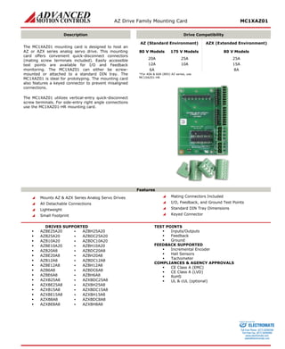
The MC1XAZ01 mounting card is designed to host AZ or AZX series analog servo drives. It offers quick-disconnect connectors and accessible test points for I/O and feedback monitoring. The mounting card can be screw mounted or attached to a DIN tray and is compatible with a range of AZ and AZX series drives from 6A to 60A.

Recommended
More Related Content
What's hot
What's hot (20)
Viewers also liked
Viewers also liked (14)
Similar to Advanced motion controls mc1xaz01
Similar to Advanced motion controls mc1xaz01 (20)
More from Electromate
More from Electromate (20)
Recently uploaded
Recently uploaded (20)
Advanced motion controls mc1xaz01
- 1. AZ Drive Family Mounting Card MC1XAZ01 Description Drive Compatibility The MC1XAZ01 mounting card is designed to host an AZ or AZX series analog servo drive. This mounting card offers convenient quick-disconnect connectors (mating screw terminals included). Easily accessible test points are available for I/O and Feedback monitoring. The MC1XAZ01 can either be screw- mounted or attached to a standard DIN tray. The MC1XAZ01 is ideal for prototyping. The mounting card also features a keyed connector to prevent misaligned connections. The MC1XAZ01 utilizes vertical-entry quick-disconnect screw terminals. For side-entry right angle connections use the MC1XAZ01-HR mounting card. AZ (Standard Environment) AZX (Extended Environment) 80 V Models 175 V Models 80 V Models 20A 25A 25A 12A 10A 15A 6A 8A *For 40A & 60A (80V) AZ series, use MC1XAZ01-HR Features Mounts AZ & AZX Series Analog Servo Drives All Detachable Connections Lightweight Small Footprint Mating Connectors Included I/O, Feedback, and Ground Test Points Standard DIN Tray Dimensions Keyed Connector DRIVES SUPPORTED AZBE25A20 ▪ AZBH25A20 AZB25A20 ▪ AZBDC25A20 AZB10A20 ▪ AZBDC10A20 AZBE10A20 ▪ AZBH10A20 AZB20A8 ▪ AZBDC20A8 AZBE20A8 ▪ AZBH20A8 AZB12A8 ▪ AZBDC12A8 AZBE12A8 ▪ AZBH12A8 AZB6A8 ▪ AZBDC6A8 AZBE6A8 ▪ AZBH6A8 AZXB25A8 ▪ AZXBDC25A8 AZXBE25A8 ▪ AZXBH25A8 AZXB15A8 ▪ AZXBDC15A8 AZXBE15A8 ▪ AZXBH15A8 AZXB8A8 ▪ AZXBDC8A8 AZXBE8A8 ▪ AZXBH8A8 TEST POINTS Inputs/Outputs Feedback Ground FEEDBACK SUPPORTED Incremental Encoder Hall Sensors Tachometer COMPLIANCES & AGENCY APPROVALS CE Class A (EMC) CE Class A (LVD) RoHS UL & cUL (optional) ELECTROMATE Toll Free Phone (877) SERVO98 Toll Free Fax (877) SERV099 www.electromate.com sales@electromate.com Sold & Serviced By:
- 2. AZ Drive Family Mounting Card MC1XAZ01 SPECIFICATIONS Mechanical Specifications Description Units Value Agency Approvals - CE Class A (EMC), CE Class A (LVD), RoHS, UL & cUL (optional) Size (H x W x D)** mm (in) 101.6 x 71.9 x 15.7 (4.00 x 2.83 x 0.54) Weight (with mating connectors) g (oz) 58.3 (2.1) P1 Connector - 16-pin, 2.54 mm spaced header P2 Connector - 22-pin, 2.54 mm spaced, dual-row header P3 Connector - 22-pin, 2.54 mm spaced, dual-row header P4 Connector* - 8-port, 3.5 mm spaced insert connector P5 Connector* - 8-port, 3.5 mm spaced insert connector P6 Connector* - 4-port, 5.08 mm spaced insert connector P7 Connector* - 3-port, 5.08 mm spaced insert connector *Mating Connector Included **Depth value is without mating connectors. See mounting dimensions drawing for depth with mating connectors installed. The total depth with an AZ servo drive mounted on the card will be equivalent to the depth dimension of the servo drive (including pins). See specific drive datasheet mounting dimensions drawing for value. Information on Approvals and Compliances UL approval optional based on customer request. Contact ADVANCED Motion Controls for more information. US and Canadian safety compliance with UL 508c, the industrial standard for power conversion electronics. UL registered under file number E140173. Note that machine components compliant with UL are considered UL registered as opposed to UL listed as would be the case for commercial products. Compliant with European CE for both the Class A EMC Directive 2004/108/EC on Electromagnetic Compatibility (specifically EN 61000-6-4:2007 and EN 61000-6-2:2005) and LVD requirements of directive 2006/95/EC (specifically EN 60204-1:2006), a low voltage directive to protect users from electrical shock. RoHS (Reduction of Hazardous Substances) is intended to prevent hazardous substances such as lead from being manufactured in electrical and electronic equipment. ELECTROMATE Toll Free Phone (877) SERVO98 Toll Free Fax (877) SERV099 www.electromate.com sales@electromate.com Sold & Serviced By:
- 3. AZ Drive Family Mounting Card MC1XAZ01 PIN FUNCTIONS P1 – Mounting Signal Connector This connector mates directly to the drive. For pin functions refer to the drive datasheet. P2 – Mounting Power Connector This connector mates directly to the drive. For pin functions refer to the drive datasheet. P3 – Mounting Power Connector This connector mates directly to the drive. For pin functions refer to the drive datasheet. P4 – I/O Connector* Pin Name Description I/O 1 +REF IN / PWM IN Analog Input Drives: Differential Reference Input PWM Input drives: Pulse width modulated digital input command I 2 SIGNAL GND Signal Ground GND 3 -REF IN / PWM IN Analog Input Drives: Differential Reference Input PWM Input drives: Direction Input I 4 CURRENT MONITOR Current Monitor. Analog output signal proportional to the actual current output. Measure relative to signal ground. See drive datasheet for scaling factor. O 5 INHIBIT IN TTL level (+5 V) inhibit/enable input. Leave open to enable drive. Pull to ground to inhibit drive. Inhibit turns off all power devices. I 6 CURRENT REF OUT Measures the command current to the internal current-loop. Measure relative to signal ground. See drive datasheet for maximum output voltage. O 7 FAULT OUT TTL level (+5 V) output becomes high when power devices are disabled due to at least one of the following conditions: inhibit, invalid Hall state, output short circuit, over voltage, over temperature, power-up reset. O 8 VEL MONITOR OUT / TACH IN Velocity Monitor. Analog output proportional to motor speed. See drive datasheet for scaling factor. For Tachometer Velocity mode, feedback voltage range is ± 60 VDC max. O/I *Not all functions are used on every drive model. Consult the drive datasheet to see which features are included. P5 – Feedback Connector* Pin Name Description I/O 1 MOT ENC A Single-ended Encoder Input A I 2 MOT ENC B Single-ended Encoder Input B I 3 OFFSET Connection to external resistance for command offset adjustments. I 4 HALL 1 Single-ended Hall/Commutation Sensor Inputs (+5 V logic level) I 5 HALL 2 I 6 HALL 3 I 7 SIGNAL GND Signal Ground GND 8 +V HALL OUT Low Power Supply for Hall Sensors (+6 V @ 30 mA). Referenced to signal ground. Short circuit protected. O *Not all functions are used on every drive model. Consult the drive datasheet to see which features are included. P6 – Motor Power Connector Pin Name Description I/O 1 MOTOR A Motor Phase A. O 2 MOTOR B Motor Phase B. O 3 MOTOR C Motor Phase C. O 4 CHASSIS Chassis (PE Ground) PE P7 –Power Connector Pin Name Description I/O 1 POWER GND Power Ground (Common with Signal Ground). GND 2 HIGH VOLTAGE DC Power Input. I 3 CHASSIS Chassis (PE Ground) PE ELECTROMATE Toll Free Phone (877) SERVO98 Toll Free Fax (877) SERV099 www.electromate.com sales@electromate.com Sold & Serviced By:
- 4. AZ Drive Family Mounting Card MC1XAZ01 MECHANICAL INFORMATION P1 – Mounting Signal Connector Connector Information 16-pin, 2.54 mm pitch header Mating Connector No mating connector required. Mate directly to drive. P2 – Mounting Power Connector Connector Information 22-pin, 2.54 mm pitch header Mating Connector No mating connector required. Mate directly to drive. P3 – Mounting Power Connector Connector Information 22-pin, 2.54 mm pitch header Mating Connector No mating connector required. Mate directly to drive. P4 – I/O Connector Connector Information 8-port, 3.5 mm spaced insert connector Mating Connector Details Phoenix Contact: P/N 1840421 Included with Drive Yes 1+REF IN / PWM IN2SIGNAL GND3-REF IN / PWM IN4CURRENT MONITOR5INHIBIT IN6CURRENT REF OUT7FAULT OUT8VEL MONITOR OUT / TACH IN P5 – Feedback Connector Connector Information 8-port, 3.5 mm spaced insert connector Mating Connector Details Phoenix Contact: P/N 1840421 Included Yes 1MOT ENC A2MOT ENC B3OFFSET4HALL 15HALL 26HALL 37SIGNAL GND8+V HALL OUT ELECTROMATE Toll Free Phone (877) SERVO98 Toll Free Fax (877) SERV099 www.electromate.com sales@electromate.com Sold & Serviced By:
- 5. AZ Drive Family Mounting Card MC1XAZ01 P6 – Motor Power Connector Connector Information 4-port, 5.08 mm spaced insert connector Mating Connector Details Phoenix Contact: P/N 1757035 or 1777303 (vertical screw terminal) Included Yes MOTOR A1MOTOR B2MOTOR C3CHASSIS4 P7 – Power Connector Connector Information 3-port, 5.08 mm spaced insert connector Mating Connector Details Phoenix Contact: P/N 1757022 or 1777293 (vertical screw terminal) Included Yes 1GND2HIGH VOLTAGE3CHASSIS ELECTROMATE Toll Free Phone (877) SERVO98 Toll Free Fax (877) SERV099 www.electromate.com sales@electromate.com Sold & Serviced By:
- 6. AZ Drive Family Mounting Card MC1XAZ01 HARDWARE NOTES The MC1XAZ01 mounting card is designed for easy installation and integration by means of quick disconnect screw-terminals and the ability to easily slide into a standard sized DIN mounting tray. The MC1XAZ01 can also be mounted to a panel or other plane surface by means of four screw-mount locations on the mounting card PCB. The photo below shows an AZ-series amplifier installed onto the MC1XAZ01, which is inserted in a DIN mounting tray, with I/O, Feedback, and Power mating connectors shown alongside (amplifier and mounting tray not included with MC1XAZ01 mounting card). DIN MOUNTING TRAY EXAMPLE: Manufacturer: Phoenix Contact ® INCLUDED CONNECTORS: Manufacturer: Phoenix Contact ® 3-position 5.08 mm spaced plug terminal (1 quantity, manufacturer part number: 1757022) 4-position 5.08 mm spaced plug terminal (1 quantity, manufacturer part number: 1757035) 8-position 3.5 mm spaced plug terminal (2 quantity, manufacturer part number: 1840421) ELECTROMATE Toll Free Phone (877) SERVO98 Toll Free Fax (877) SERV099 www.electromate.com sales@electromate.com Sold & Serviced By:
- 7. AZ Drive Family Mounting Card MC1XAZ01 MOUNTING DIMENSIONS ELECTROMATE Toll Free Phone (877) SERVO98 Toll Free Fax (877) SERV099 www.electromate.com sales@electromate.com Sold & Serviced By:
- 8. AZ Drive Family Mounting Card MC1XAZ01 PART NUMBERING INFORMATION XDrive IndicatorIndicates the drive type(s) compatible with the mounting cardAxisNumber of axis supportedProduct TypeMC indicates mounting cardRevisionOmit from part number when orderingSeriesMounting card seriesMC1AZ01Additional OptionsHR: High current, Right entry wires All analog servo drive accesories listed in the selection tables of the website are readily available, standard product offerings. However, additional features and/or options are available for select drives and other possibilities can be made available for OEMs with sufficient volume requests. Feel free to contact Applications Engineering for further information and details. All specifications in this document are subject to change without written notice. Actual product may differ from pictures provided in this document. ELECTROMATE Toll Free Phone (877) SERVO98 Toll Free Fax (877) SERV099 www.electromate.com sales@electromate.com Sold & Serviced By: