Table of
Contents
• ADASoverview
• ADAS Vehicle Architectures
• ADAS
Technologies/Sensors
• Vision(Cameras) System
• LiDAR System
• Radar System
• GNSS/IMU System
• V2X System
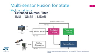
• Sensor Fusion Example
2
ST
Confidential
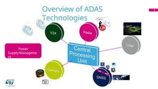
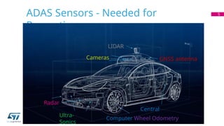
ADAS Sensors -Needed for
Perception
5
LIDAR
Radar
Cameras GNSS antenna
Ultra-
Sonics
Central
Computer Wheel Odometry
6.
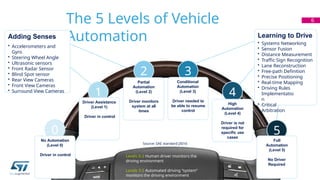
The 5 Levelsof Vehicle
Automation
6
2
Partial
Automation
(Level 2)
Driver monitors
system at all
times
4
High
Automation
(Level 4)
Driver is not
required for
specific use
cases
Learning to Drive
• Systems Networking
• Sensor Fusion
• Distance Measurement
• Traffic Sign Recognition
• Lane Reconstruction
• Free-path Definition
• Precise Positioning
• Real-time Mapping
• Driving Rules
Implementatio
n
• Critical
Arbitration
Adding Senses
• Accelerometers and
Gyro
• Steering Wheel Angle
• Ultrasonic sensors
• Front Radar Sensor
• Blind Spot sensor
• Rear View Cameras
• Front View Cameras
• Surround View Cameras
0
No Automation
(Level 0)
Driver in control
5
Full
Automation
(Level 5)
No Driver
Required
1
Driver Assistance
(Level 1)
Driver in control
3
Conditional
Automation
(Level 3)
Driver needed to
be able to resume
control
Levels 0-2 Human driver monitors the
driving environment
Levels 3-5 Automated driving “system”
monitors the driving environment
Source: SAE standard J3016
7.
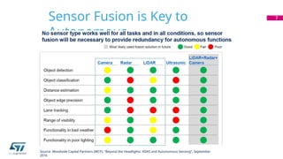
Sensor Fusion isKey to
Autonomous
7
Source: Woodside Capital Partners (WCP), “Beyond the Headlights: ADAS and Autonomous Sensing”, September
2016
Distributed vs Centralized
Processing
•Distributed
Interfaces
• ETH, SPI, I2C, CAN, CAN-FD
• RADAR, Ultrasonic, V2X, IMU, Wheel Odomerty, GNSS
• MIPI(CSI-2), GMSL(Maxim), FPD-Link(TI), PCIe, HDBaseT(Valens)
• Video Cameras?
• Lidar?
9
Ultrasonic
Lidar
Radar
Camera
V2X
Rotation
ä
Acceleration &
ṽ Speed
GNSS
Vehicle
State
NLOS
LOS
Processor
Processor
Processor
Processor
Processor
Processor
Processor
Processor
Sensor Fusion,
Motion
Planning, and
Driver
warnings
Intelligent
Edge
Processing
Vehicle Dynamics
and Control
Infotainment & Cluster
MCU /MPU /DSP
RF
Sensors
Think!
Sense
ACT
ETH / SPI /
CAN / CAN-FD
Breaking
Steering
Acceleratin
g
… .
Object
data
Late Sensor Fusion
Distributed Processing with Object Level Fusion Centralized Processing with Raw Data
Fusion
LOS: Line-of-Sight
NLOS: Non-Line-of-
Sight
• Centralized
Interfaces
• ETH, SPI, I2C, CAN, CAN-FD
• V2X, IMU, Wheel Odomerty, GNSS
• MIPI(CSI-2), GMSL(Maxim), FPD-Link(TI), PCIe, HDBaseT(Valens)
• Radar, Ultrasonic
• Cameras
• Lidar?
Ultrasonic
Lidar
Radar
Camera
V2X
Rotation
ä
Acceleration &
ṽ Speed
GNSS
Vehicle
State
NLOS
LOS
Processor
Processor
Processor
Processor
Sensor Fusion,
Motion
Planning, and
Driver
warnings
Raw Data
Capture
(I/Q)
Vehicle Dynamics
and
Control
Infotainment & Cluster
MCU /MPU /DSP
RF
Sensors
Think!
Sense
ACT
ETH / SPI /
CAN / CAN-FD
Breaking
Steering
Accelerating
… .
Raw
Data
Sensor Hybrid Fusion
No
Processing
Early Data
from
Sensors
10.
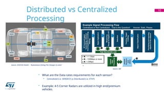
Distributed vs Centralized
Processing
10
Source:2018 IHS Markit – “Autonomous Driving-The Changes to come”
Source: ADI
• What are the Data rates requirements for each sensor?
• Centralized (i.e. SERDES?) vs Distributed (i.e. ETH?)
• Example: 4-5 Corner Radars are utilized in high end/premium
vehicles.
Camera
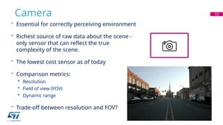
• Essential forcorrectly perceiving environment
• Richest source of raw data about the scene -
only sensor that can reflect the true
complexity of the scene.
• The lowest cost sensor as of today
• Comparison metrics:
• Resolution
• Field of view (FOV)
• Dynamic range
• Trade-off between resolution and FOV?
12
13.
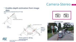
Camera-Stereo
• Enables depthestimation from image
data
13
Left and right
images
Find a point in 3D by
triangulation!
Source: Sanja Fidler, CSC420: Intro to Image
Understanding
All points on projective line to P map
to p
One
camera Add a
second
camer
a
14.
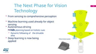
The Next Phasefor Vision
Technology
• From sensing to comprehensive perception
• Machine learning used already for object
sensing
• Autonomous driving
needs
• Path planning based on holistic cues
• Dynamic following of the drivable
area
• Deep learning is now being
applied
14
150°
30°
1
50°
2
3
15.
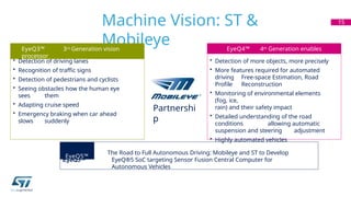
Machine Vision: ST&
Mobileye
15
• Detection of driving lanes
• Recognition of traffic signs
• Detection of pedestrians and cyclists
• Seeing obstacles how the human eye
sees them
• Adapting cruise speed
• Emergency braking when car ahead
slows suddenly
EyeQ3™ 3rd Generation vision
processor
EyeQ4™ 4th Generation enables
• Detection of more objects, more precisely
• More features required for automated
driving Free-space Estimation, Road
Profile Reconstruction
• Monitoring of environmental elements
(fog, ice,
rain) and their safety impact
• Detailed understanding of the road
conditions allowing automatic
suspension and steering adjustment
• Highly automated vehicles
Partnershi
p
EyeQ5TM
The Road to Full Autonomous Driving: Mobileye and ST to Develop
EyeQ®5 SoC targeting Sensor Fusion Central Computer for
Autonomous Vehicles
EyeQ5™
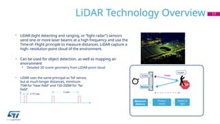
LiDAR Technology Overview17
distance
Photon
Measured
distance =
Speed of
light
x
Photon
travel
time /2
Emitte
r
Receiver
• LiDAR (light detecting and ranging, or “light radar”) sensors
send one or more laser beams at a high frequency and use the
Time-of- Flight principle to measure distances. LiDAR capture a
high- resolution point cloud of the environment.
• Can be used for object detection, as well as mapping an
environment
• Detailed 3D scene geometry from LIDAR point cloud
• LiDAR uses the same principal as ToF sensor,
but at much longer distances, minimum
75M for “near field” and 150-200M for “far
field”.
Targets
2 µsec
2-10 nsec
18.
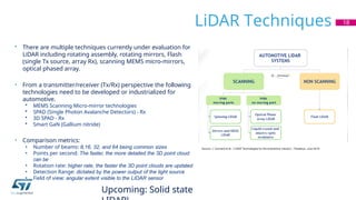
LiDAR Techniques 18
•There are multiple techniques currently under evaluation for
LiDAR including rotating assembly, rotating mirrors, Flash
(single Tx source, array Rx), scanning MEMS micro-mirrors,
optical phased array.
• From a transmitter/receiver (Tx/Rx) perspective the following
technologies need to be developed or industrialized for
automotive.
• MEMS Scanning Micro-mirror technologies
• SPAD (Single Photon Avalanche Detectors) - Rx
• 3D SPAD - Rx
• Smart GaN (Gallium nitride)
• Comparison metrics:
• Number of beams: 8,16, 32, and 64 being common sizes
• Points per second: The faster, the more detailed the 3D point cloud
can be
• Rotation rate: higher rate, the faster the 3D point clouds are updated
• Detection Range: dictated by the power output of the light source
• Field of view: angular extent visible to the LIDAR sensor
Upcoming: Solid state
19.
LiDAR Summary
• Autonomousvehicles have been around for quite some time but only
now the
technologies are available for practical implementations
• No single sensor solution exists to cover all aspects – range,
accuracy, environmental conditions, color discrimination, latency
etc.
• Multi-sensor fusion and integration will be a must
• Each technology attempts to solve the overall problem while having multiple
limitations
• Many LiDAR solutions (technologies) are available or being proposed
with no clear winners
• Market is still in very early stage of development and experimentation
• When and which technology or system will be widely adopted and
mass production starts is still unknown
19
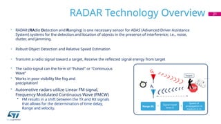
RADAR Technology Overview21
• RADAR (RAdio Detection and Ranging) is one necessary sensor for ADAS (Advanced Driver Assistance
System) systems for the detection and location of objects in the presence of interference; i.e., noise,
clutter, and jamming.
• Robust Object Detection and Relative Speed Estimation
• Transmit a radio signal toward a target, Receive the reflected signal energy from target
• The radio signal can the form of “Pulsed” or “Continuous
Wave”
• Works in poor visibility like fog and
precipitation!
• Automotive radars utilize Linear FM signal,
Frequency Modulated Continuous Wave (FMCW)
• FM results in a shift between the TX and RX signals
that allows for the determination of time delay,
Range and velocity.
distance
Range (R) =
Speed of
propagation in
medium (c in
air)
x
Signal travel
time /2
Targets
Gt
Ar
22.
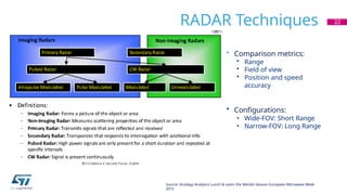
RADAR Techniques 22
Source:Strategy Analytics Lunch & Learn the Market Session European Microwave Week
2013
• Comparison metrics:
• Range
• Field of view
• Position and speed
accuracy
• Configurations:
• Wide-FOV: Short Range
• Narrow-FOV: Long Range
23.
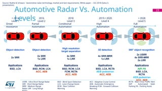
Automotive Radar Vs.Automation
Levels
23
< 2014
Level 1
Driver
Assistance
2016
Level 2
Partial
Automation
2018
Level 3
Conditional
Automation
2019 / 2020
Level 4
High
Automation
> 2028
Level 5
Full
Automation
Object detection Object detection
High resolution
target separation
4x SRR
1x LRR
3D detection 360° object recognition
2x USRR
4x SRR-MRR
2x LRR
2x SRR
2x SRR
1x LRR
4x SRR-MRR
1x LRR
Applications
BSD, LCA
Applications
BSD, RCW, LCA
ACC, AEB
Applications
BSD, RCW, LCA
FCW, RCTA
ACC, AEB
Applications
BSD, LCA, RCTA
AEB pedestrian
ACC, AEB
Applications
AVP, PA
BSD, LCA,
RCTA
AEB pedestrian
ACC, AEB
BSD - Blind Sport Detection
LCA - Lane Change Assist
RCW - Rear Collision
Warning
ACC - Adaptive Cruise Control
AEB - Automatic Emergency
Breaking FCW - Forward Collision
Warning
RCTA - Rear Cross Traffic Alert
AVP - Automated Valet
Parking PA - Parking Assist
USRR - Ultra Short Range Radar
SRR - Short Range Radar
MRR - Medium Range
Radar LRR - Long Range
Source: Rodhe & Schwarz - Automotive radar technology, market and test requirements, White paper – Oct 2018 (Salvo S.
presentation)
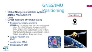
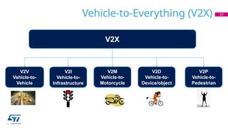
GNSS/IMU
Positioning
• Global NavigationSatellite Systems
and
Inertial Measurement
Units
• Direct measure of vehicle states
• Positioning, velocity, and time
(GNSS)
• Varying accuracies: Real-time Kinematic (RTK-
short base line), Precise Point Positioning
(PPP), Differential Global Positioning System
(DGPS), Satellite-based augmentation system
(SBAS- Ionospheric delay correction)
• Angular rotation rate
(IMU)
• Acceleration (IMU)
• Heading (IMU, GPS)
25
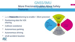
GNSS/IMU
26.
• Lane detection
•Positioning data for V2X
sharing
• Collision avoidance
• Autonomous parking
• Autonomous driving
• eCall accident location
GNSS/IMU
Positioning
26
0
Multi Band
L1, L2 and L5,
i.e. GPS
<30cm
More Precision Enables More Safety
Features
Precise Positioning: Towards Autonomous
Driving Precise Positioning to enable < 30cm precision
GPS
GLONASS
BeiDo
u
Galileo
QZSS
SBAS
Carrier
Phase RTK
PPP
Sensor
fusion
27.
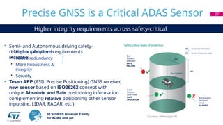
Higher integrity requirementsacross safety-critical
applications
• Semi- and Autonomous driving safety-
related applications requirements
increase
• Higher safety levels
• Added redundancy
• More Robustness &
integrity
• Security
• Teseo APP (ASIL Precise Positioning) GNSS receiver,
new sensor based on ISO26262 concept with
unique Absolute and Safe positioning information
complementing relative positioning other sensor
inputs(i.e. LIDAR, RADAR, etc.)
ST‘s GNSS Receiver Family
for ADAS and AD
Precise GNSS is a Critical ADAS Sensor 27
Courtesy of Hexagon PI
Bad Solution
Declared
Good
HAZARD!
Bad
Solution
Detected
SAFE
FAILURE
Good
Solution
Confirmed
SAFE
OPERATION
HPL – Horizontal Protection
Level
VPL – Vertical Protection Level
28.
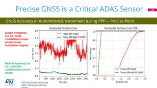
GNSS Accuracy inAutomotive Environment (using PPP – Precise Point
Positioning)
Precise GNSS is a Critical ADAS Sensor 28
Single Frequency
(i.e. L1) multi-
constellation/code-
phase(1msec
modulation signal)
Multi Frequency (i.e.
L1, L2) multi-
constellation/carrier-
phase
APP: ASIL Precise Positioning
SWPE: Software Positioning
29.
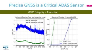
GNSS Integrity –Protection
Levels
Precise GNSS is a Critical ADAS Sensor 29
5.875 5.895 5.905
5.885
Frequency
[GHz]
Channel
172
Collision
Avoidance
Safety
(V2V)
&
Safety
of
Life
Channel
174
Shared
Public
Safety/Privat
e
Service
Channel
176
Shared
Public
Safety/Privat
e
Service
Channel175
Channel
178
Control
Channel
Announces
Services
on
other
channels
Gov’t Only
use Limit
Channel
180
Shared
Public
Safety/Privat
e
Service
Channel
182
Shared
Public
Safety/Privat
e
Service
Channel 181
Channel
184
Dedicated
Public
Safety
Reserved
Unknown
EIRP
5.845 5.850 5.855 5.865
44.8
40.0
33.0
23.0
0.00
EIRP
[dBm]
(not
to
scale)
FCC Spectrum Allocation for DSRC of ITS 3
2
32
EIRP: Effective Isotropic Radiated Power
ITS: Intelligent Transportation Systems
Source: Federal Communications Commission FCC 03-324
• BSM (V2V)
• MAP Message (V2I)
• SPAT (V2I)
• TX Power +20dBm
5.915
5.925
• Road authorities
and public agencies
primarily
responsible for
usage
• Control Channel,
Advertises and indicates
how to access services on
other “Service channels”
33.
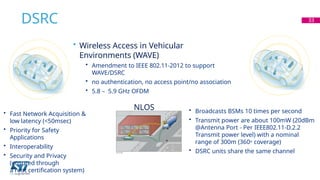
DSRC 33
NLOS
• WirelessAccess in Vehicular
Environments (WAVE)
• Amendment to IEEE 802.11-2012 to support
WAVE/DSRC
• no authentication, no access point/no association
• 5.8 – 5.9 GHz OFDM
• Fast Network Acquisition &
low latency (<50msec)
• Priority for Safety
Applications
• Interoperability
• Security and Privacy
(ensured through
a root certification system)
• Broadcasts BSMs 10 times per second
• Transmit power are about 100mW (20dBm
@Antenna Port - Per IEEE802.11-D.2.2
Transmit power level) with a nominal
range of 300m (360o coverage)
• DSRC units share the same channel
34.
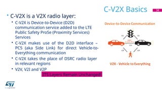
C-V2X Basics
• C-V2Xis a V2X radio layer:
• C-V2X is Device-to-Device (D2D)
communication service added to the LTE
Public Safety ProSe (Proximity Services)
Services
• C-V2X makes use of the D2D interface –
PC5 (aka Side Link) for direct Vehicle-to-
Everything communication
• C-V2X takes the place of DSRC radio layer
in relevant regions
• V2V, V2I and V2P
34
ITS Layers Remain Unchanged!
35.
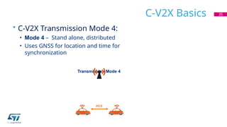
C-V2X Basics
• C-V2XTransmission Mode 4:
• Mode 4 – Stand alone, distributed
• Uses GNSS for location and time for
synchronization
Transmission Mode 4
35
PC5
36.
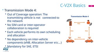
C-V2X Basics
• TransmissionMode 4:
• Out of Coverage operation: The
transmitting vehicle is not connected to
the network
• No SIM card or inter-operator
collaboration is required
• Each vehicle performs its own scheduling
and allocation
• No dependency on inter-vehicle
components (eNB, Allocation Server etc…)
• Mandatory for SAE, ETSI
36
PC5
PC5
PC5
Transmission Mode 4
PC5
37.
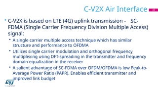
C-V2X Air Interface
•C-V2X is based on LTE (4G) uplink transmission - SC-
FDMA (Single Carrier Frequency Division Multiple Access)
signal:
• A single carrier multiple access technique which has similar
structure and performance to OFDMA
• Utilizes single carrier modulation and orthogonal frequency
multiplexing using DFT-spreading in the transmitter and frequency
domain equalization in the receiver
• A salient advantage of SC-FDMA over OFDM/OFDMA is low Peak-to-
Average Power Ratio (PAPR). Enables efficient transmitter and
improved link budget
37
38.
In
Summary
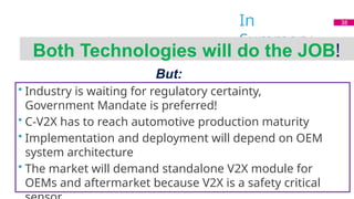
Both Technologies willdo the JOB!
But:
• Industry is waiting for regulatory certainty,
Government Mandate is preferred!
• C-V2X has to reach automotive production maturity
• Implementation and deployment will depend on OEM
system architecture
• The market will demand standalone V2X module for
OEMs and aftermarket because V2X is a safety critical
38


![5.875 5.895 5.905
5.885
Frequency
[GHz]
Channel
172
Collision
Avoidance
Safety
(V2V)
&
Safety
of
Life
Channel
174
Shared
Public
Safety/Privat
e
Service
Channel
176
Shared
Public
Safety/Privat
e
Service
Channel 175
Channel
178
Control
Channel
Announces
Services
on
other
channels
Gov’t Only
use Limit
Channel
180
Shared
Public
Safety/Privat
e
Service
Channel
182
Shared
Public
Safety/Privat
e
Service
Channel 181
Channel
184
Dedicated
Public
Safety
Reserved
Unknown
EIRP
5.845 5.850 5.855 5.865
44.8
40.0
33.0
23.0
0.00
EIRP
[dBm]
(not
to
scale)
FCC Spectrum Allocation for DSRC of ITS 3
2
32
EIRP: Effective Isotropic Radiated Power
ITS: Intelligent Transportation Systems
Source: Federal Communications Commission FCC 03-324
• BSM (V2V)
• MAP Message (V2I)
• SPAT (V2I)
• TX Power +20dBm
5.915
5.925
• Road authorities
and public agencies
primarily
responsible for
usage
• Control Channel,
Advertises and indicates
how to access services on
other “Service channels”](https://image.slidesharecdn.com/ads-250804130750-d80ad6e0/85/Advanced-Car-Drive-assistance-System-pptx-32-320.jpg)