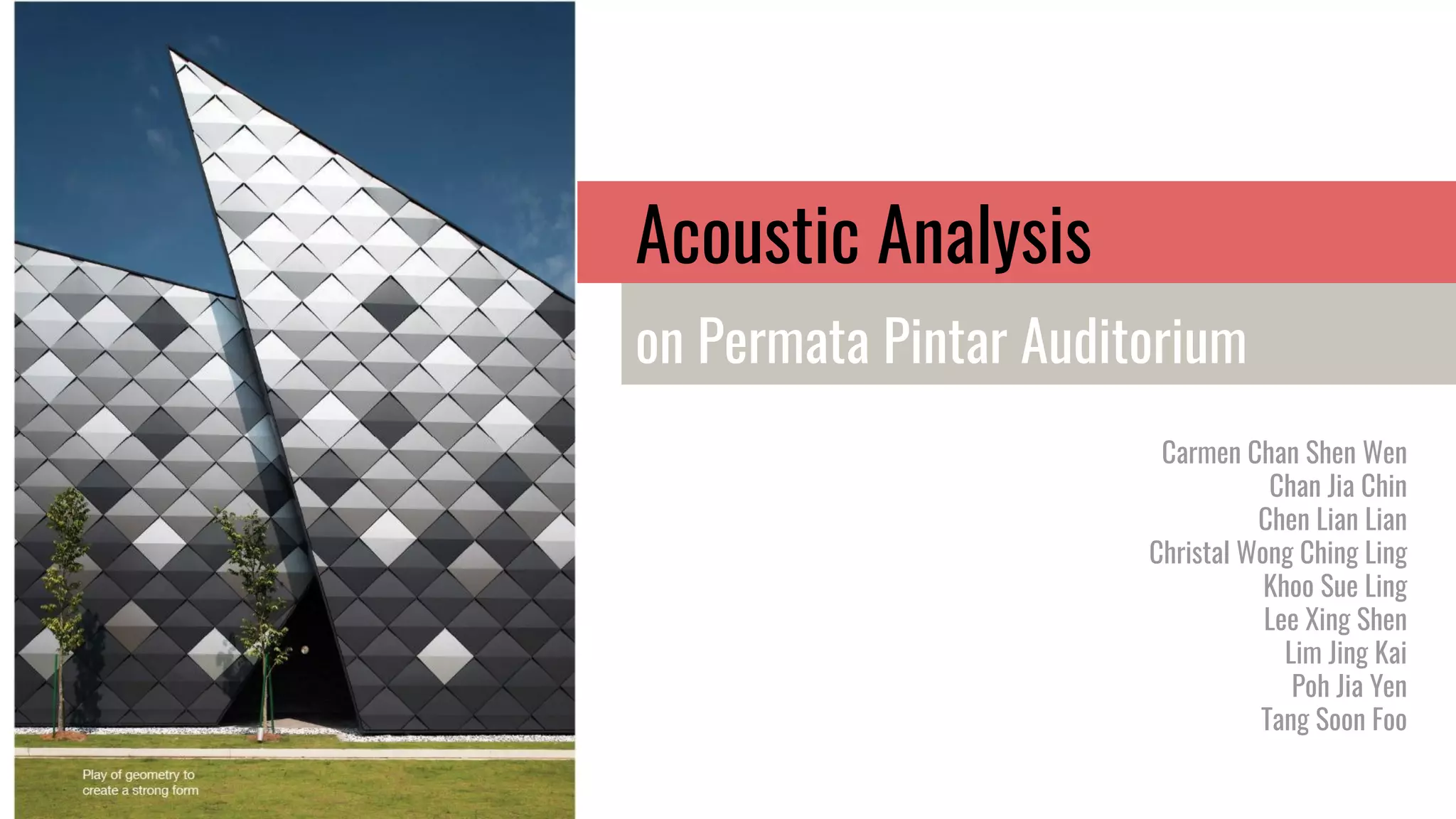
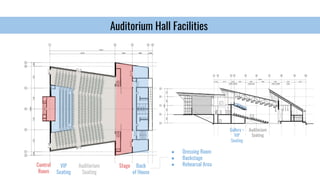
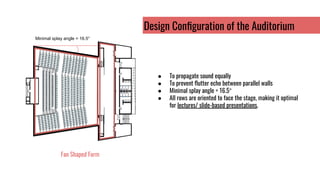
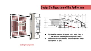
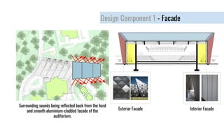
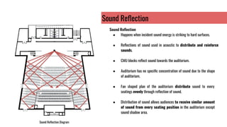
The auditorium was designed to distribute sound evenly throughout the seating areas. Several design elements help achieve this:
1. The fan-shaped layout and minimal 16.5 degree splay angle between rows allows sound to propagate equally without flutter echoes.
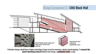
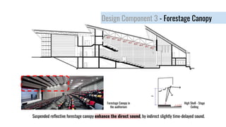
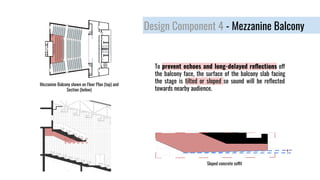
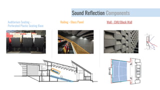
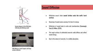
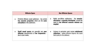
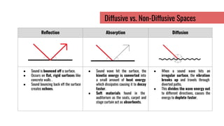
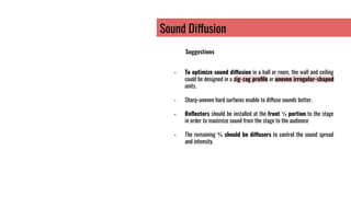
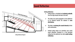
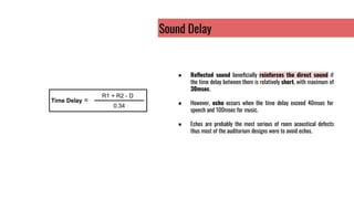
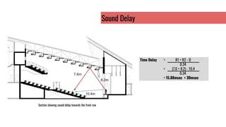
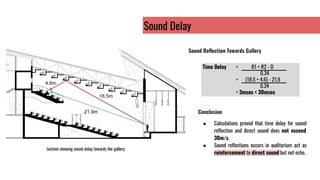
2. CMU block walls and a suspended forestage canopy reflect and diffuse sound to reinforce direct sound within 30ms of delay.
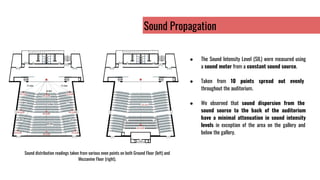
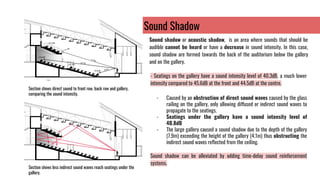
3. Measurements found sound intensity levels varied minimally except for areas under the deep gallery, which experience sound shadows due to obstruction of indirect sound waves.