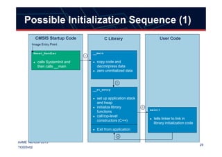
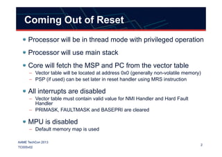
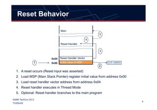
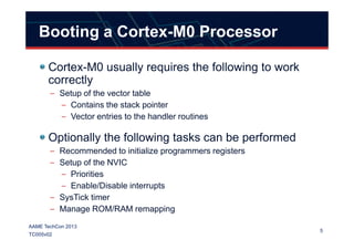
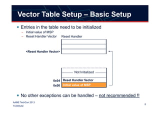
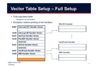
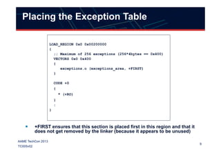
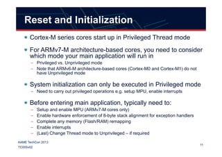
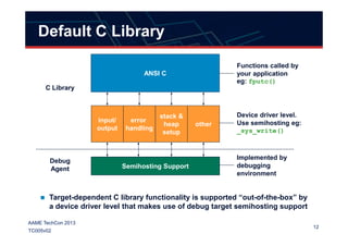
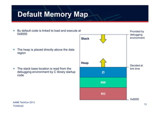
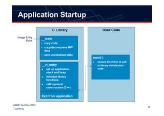
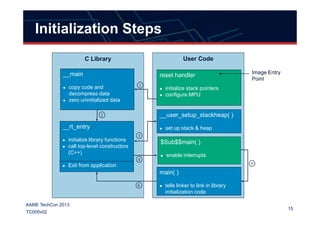
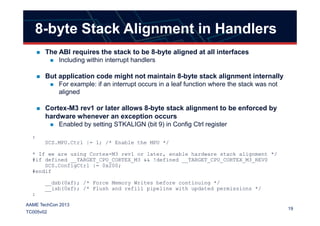
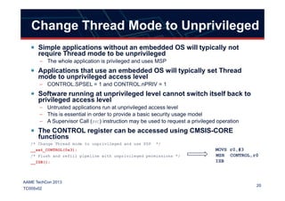
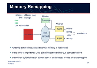
This document describes the system startup process for Cortex-M series processors. Upon reset, the processor will fetch the main stack pointer (MSP) and reset handler address from the vector table located at address 0x0. The reset handler will then execute in privileged thread mode. Interrupts are initially disabled. The MPU is also disabled initially, allowing access to all memory regions. The document then discusses setting up the vector table and performing additional initialization steps like MPU configuration in the reset handler.

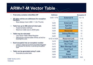
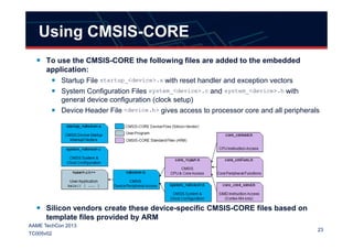
![Example Vector Table
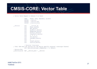
Fully populated table
vect_t vecttable[]
__attribute__ ((section("vectors"))) = {
(vect_t)(ARMIKMCU_STACKTOP), // Top of Stack
(vect_t)__main, // Reset Handler
(vect_t)NMI_Handler, // NMI Handler
(vect_t)HardFault_Handler, // Hard Fault Handler
Place the table in
“vectors” section
used by the Linker
Branch to __main
after reset
8
AAME TechCon 2013
TC005v02
(vect_t)HardFault_Handler, // Hard Fault Handler
0, 0, 0, 0, 0, 0, 0, // Reserved
(vect_t)SVC_Handler, // SVCall Handler
0, 0, // Reserved
(vect_t)PendSV_Handler, // PendSV Handler
(vect_t)SysTick_Handler, // SysTick Handler
(vect_t)Default_IRQHandler,
:
: // External Interrupts 1 – 32
:
(vect_t)Default_IRQHandler };
“Reserved” locations
maintained for
compatibility
Branch to a Default
IRQ Handler](https://image.slidesharecdn.com/aametc2013005v02-systemstartup-141125195614-conversion-gate02/85/AAME-ARM-Techcon2013-005v02-System-Startup-8-320.jpg)

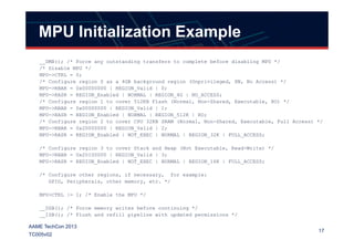
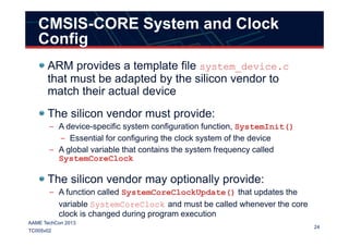
![MPU Initialization Optimization
The Region Base Address Register and Region Attribute and
Size Register are aliased
– This means up to four regions can be programmed at once using a memcpy
uint32_t mpu_config_table_1[] {
/* Configure region 0 as a background region (Unprivileged, XN, No Access) */
(REGION_Enabled | NORMAL_OUTER_INNER_NON_CACHEABLE_NON_SHAREABLE | REGION_512K | RO),
(0x00000000 | REGION_Valid | 0),
/* Configure region 1 to cover 512KB Flash (Normal, Non-Shared, Executable, Read-only) */
18
AAME TechCon 2013
TC005v02
/* Configure region 1 to cover 512KB Flash (Normal, Non-Shared, Executable, Read-only) */
(0x10000000 | REGION_Valid | 1),
(REGION_Enabled | NOT_EXEC | NORMAL | REGION_32K | FULL_ACCESS),
/* Configure region 2 to cover CPU 32KB SRAM (Normal, Non-Shared, Executable, Full Access) */
(0x20000000 | REGION_Valid | 2),
(REGION_Enabled | NOT_EXEC | NORMAL | REGION_32K | FULL_ACCESS),
/* Configure region 3 to cover Stack and Heap (Not Executable, Read/Write) */
(0x20100000 | REGION_Valid | 3),
(REGION_Enabled | DEVICE_NON_SHAREABLE | REGION_16K | FULL_ACCESS)
};
/* other tables */
mpu_setup()
{
:
memcpy((void*)&( MPU->RBAR), mpu_config_table_1, sizeof(mpu_config_table_1));
:
}](https://image.slidesharecdn.com/aametc2013005v02-systemstartup-141125195614-conversion-gate02/85/AAME-ARM-Techcon2013-005v02-System-Startup-18-320.jpg)
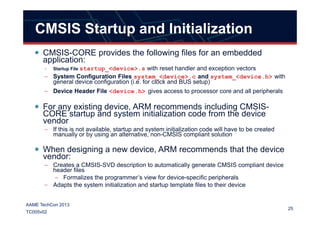
![CMSIS-CORE: Exception Handlers
; Reset Handler
Reset_Handler PROC
EXPORT Reset_Handler [WEAK]
IMPORT SystemInit
IMPORT __main
LDR R0, =SystemInit
BLX R0
LDR R0, =__main
BX R0
ENDP
:
:
28
AAME TechCon 2013
TC005v02
:
:
; Dummy Exception Handlers (infinite loops which can be modified)
NMI_Handler PROC
EXPORT NMI_Handler [WEAK]
B .
ENDP
HardFault_Handler PROC
EXPORT HardFault_Handler [WEAK]
B .
ENDP](https://image.slidesharecdn.com/aametc2013005v02-systemstartup-141125195614-conversion-gate02/85/AAME-ARM-Techcon2013-005v02-System-Startup-28-320.jpg)