Downloaded 10 times
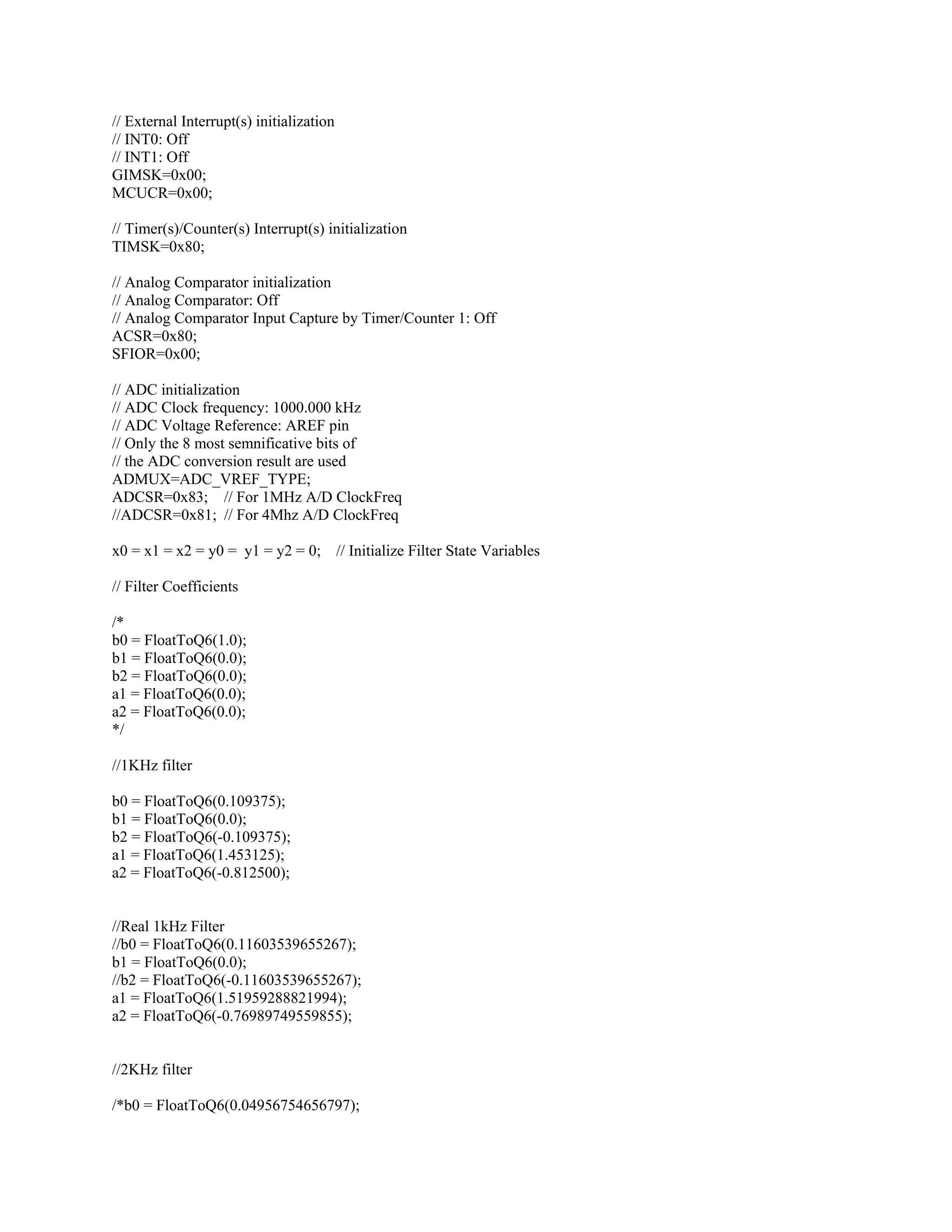
![Prewarping:
)1(
)1(2
1
1
−
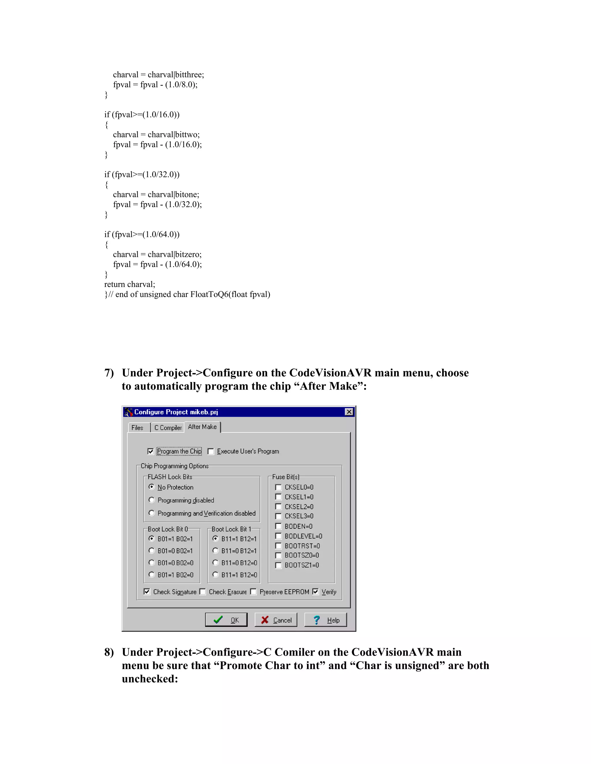
−
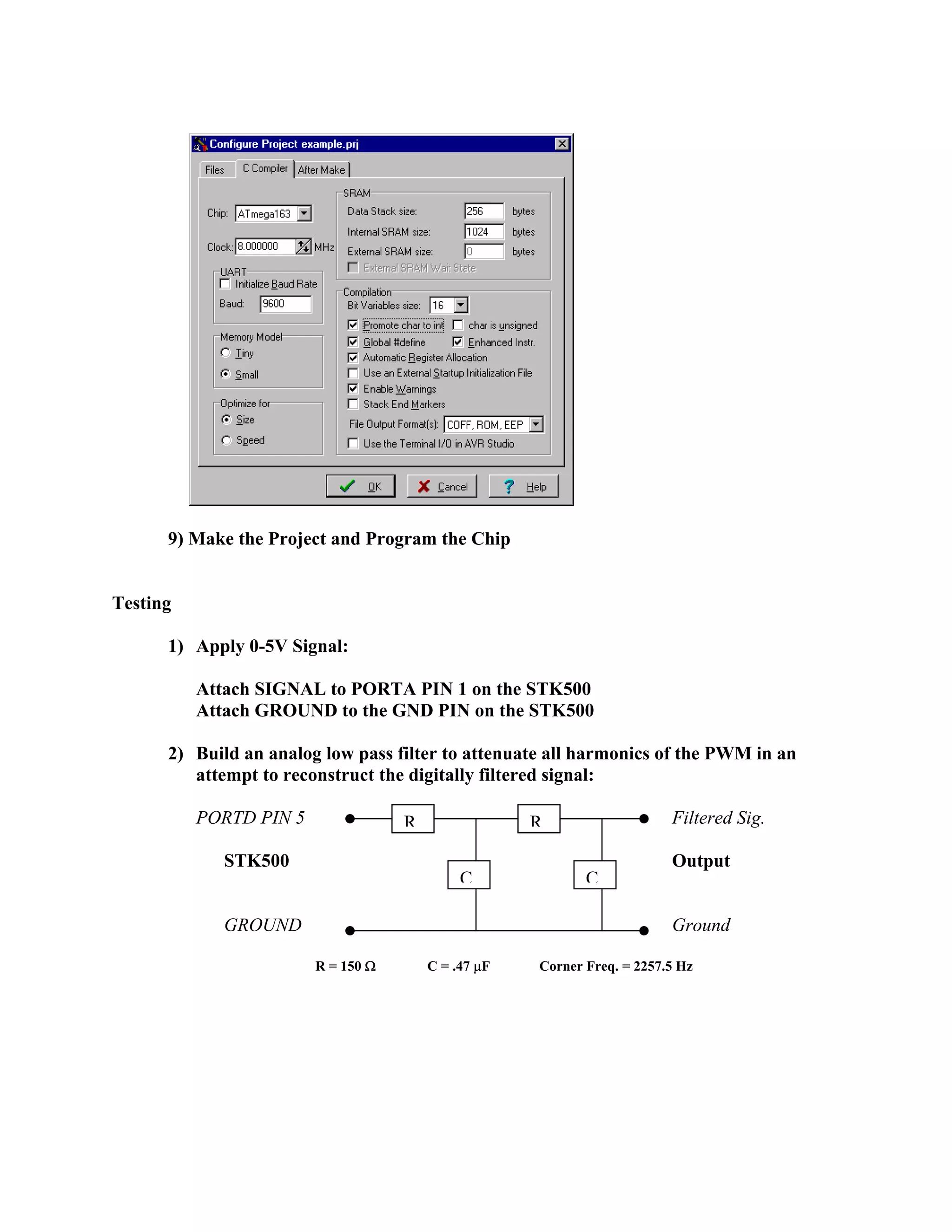
+
−
=
z
z
T
s
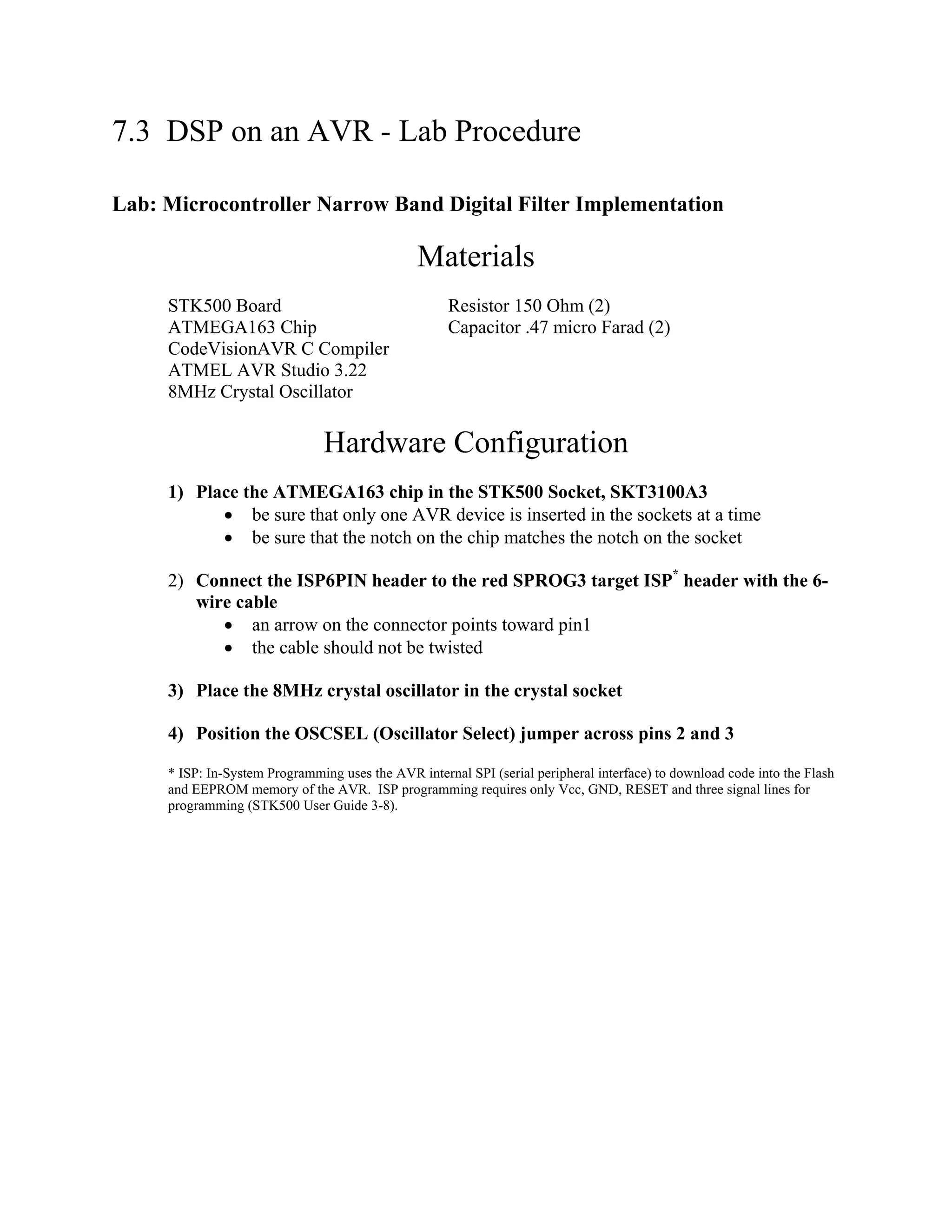
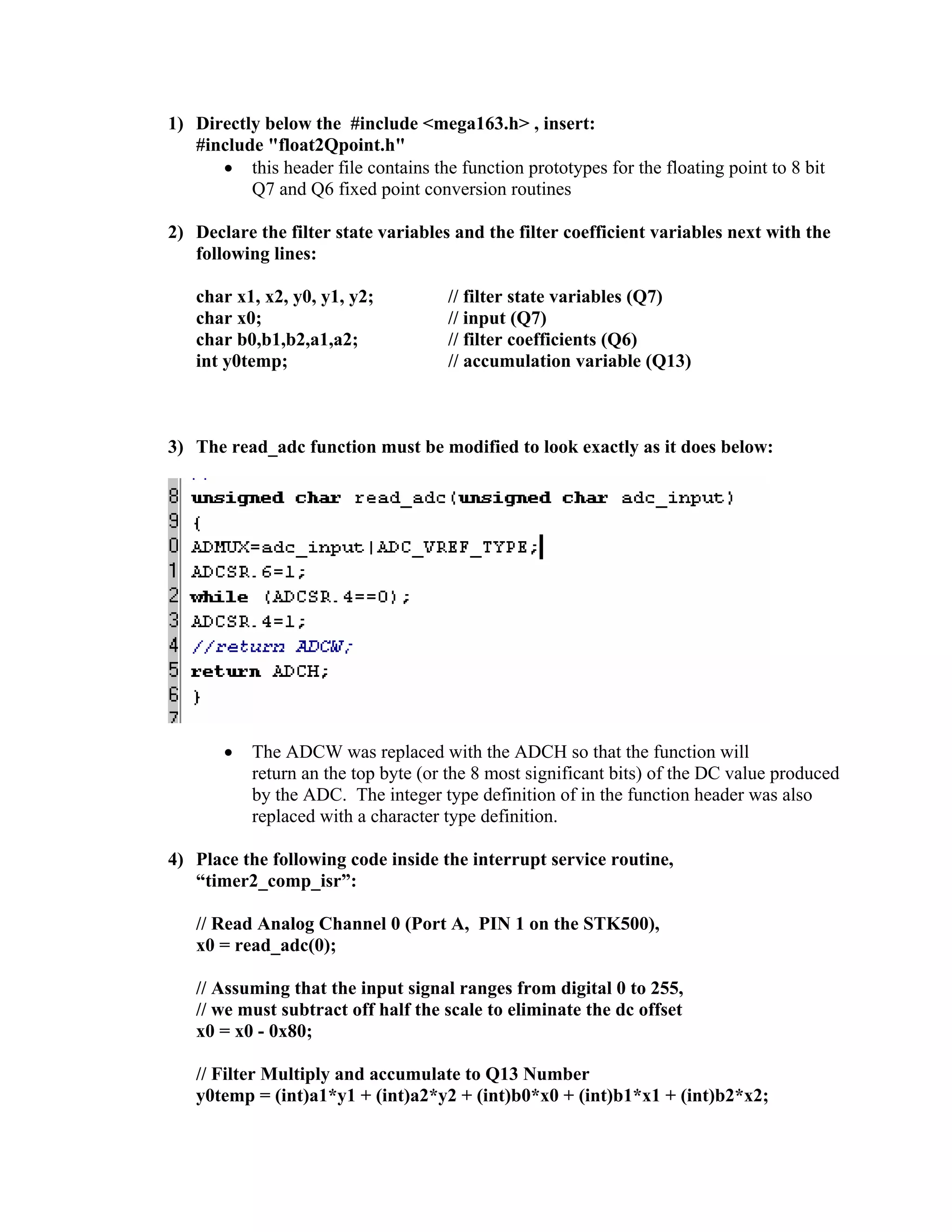
The bilinear transform does not produce a perfectly linear relationship between analog and
digital frequencies especially for higher frequencies:
)1(
)1(2
dj
dj
e
e
T
aj ω
ω
ω −
−
+
−
=
, dj
ez
ajs
ω
ω
=
=
T
fdT
fa
π
π )tan(
=
Therefore, in order to design for a center frequency (fd) and bandwidth (fd_max-fd_min) similar
to that of the analog filter, the digital filter coefficients must be calculated with
f0 = fa and B=Ba = fa_max – fa_min.
Unity gain desired at center frequency:
2222
16
2
)2(
faBaBa
faG
fajH
πππ
π
π
+
=
2222
16
2
faBa
fa
Ba
G ππ +=
Difference Equation:
]2[2]1[1][0]2[2]1[1][ −=−++−−−−= nxbnxbnxbnyanyany](https://image.slidesharecdn.com/dsp-onan-avr-101118213646-phpapp02/75/Dsp-on-an-avr-15-2048.jpg)

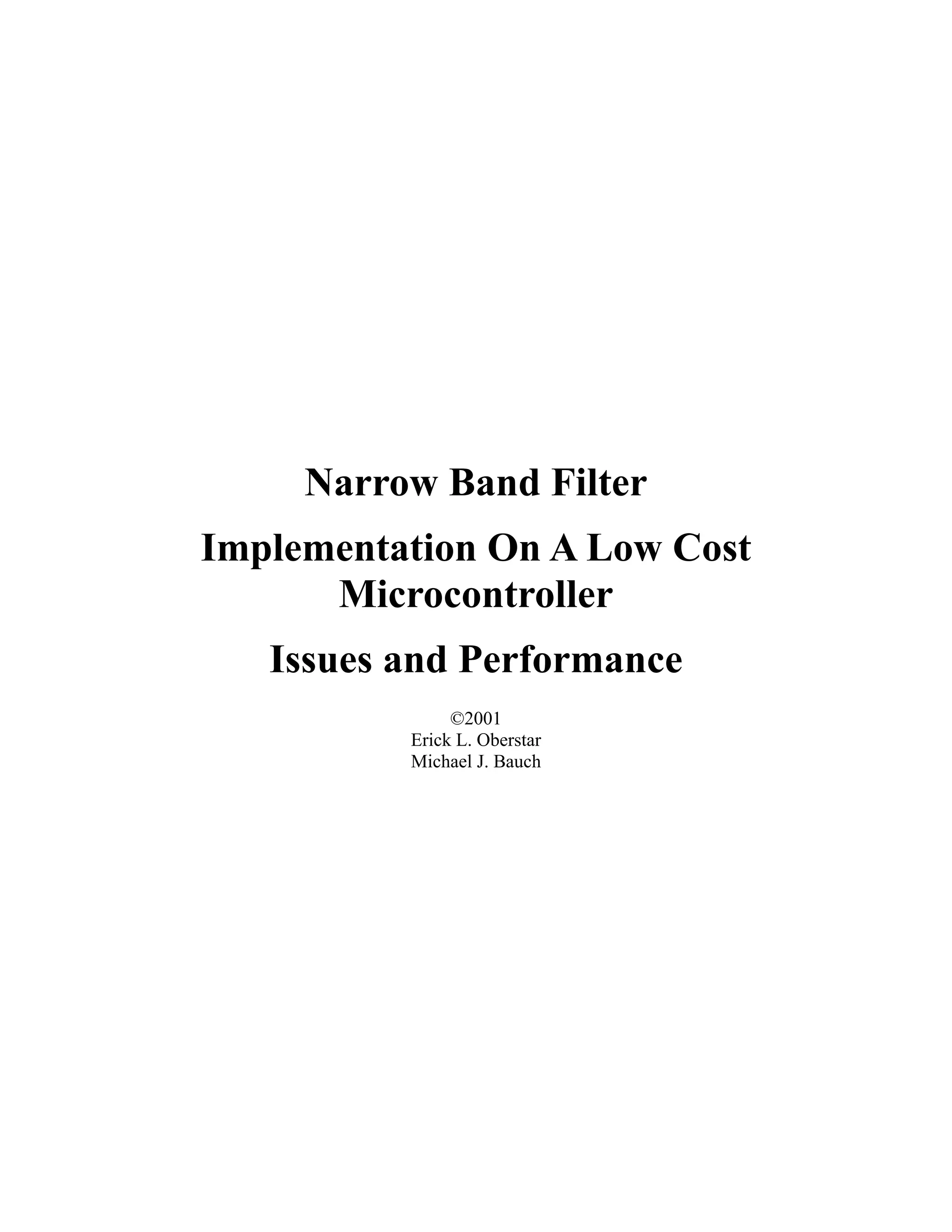
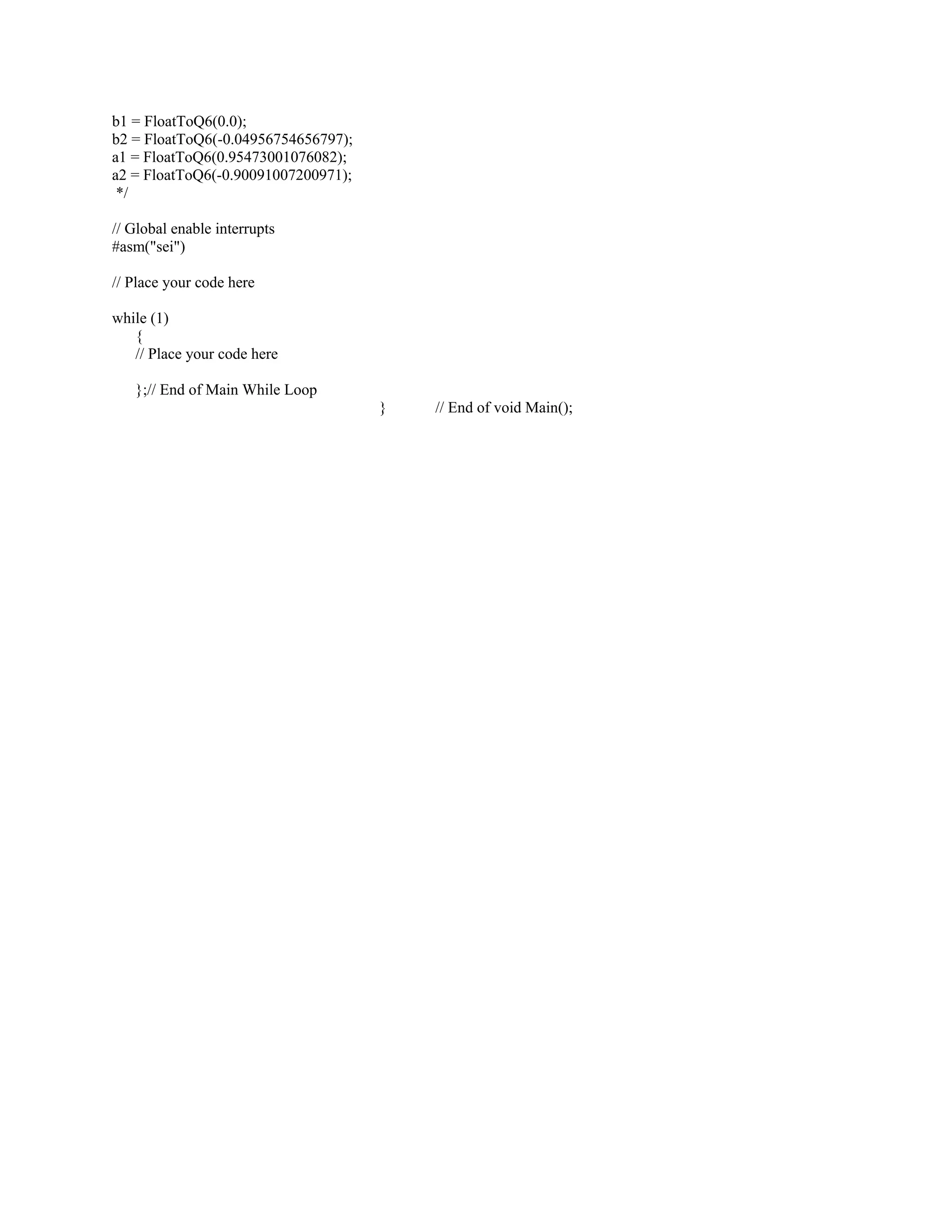
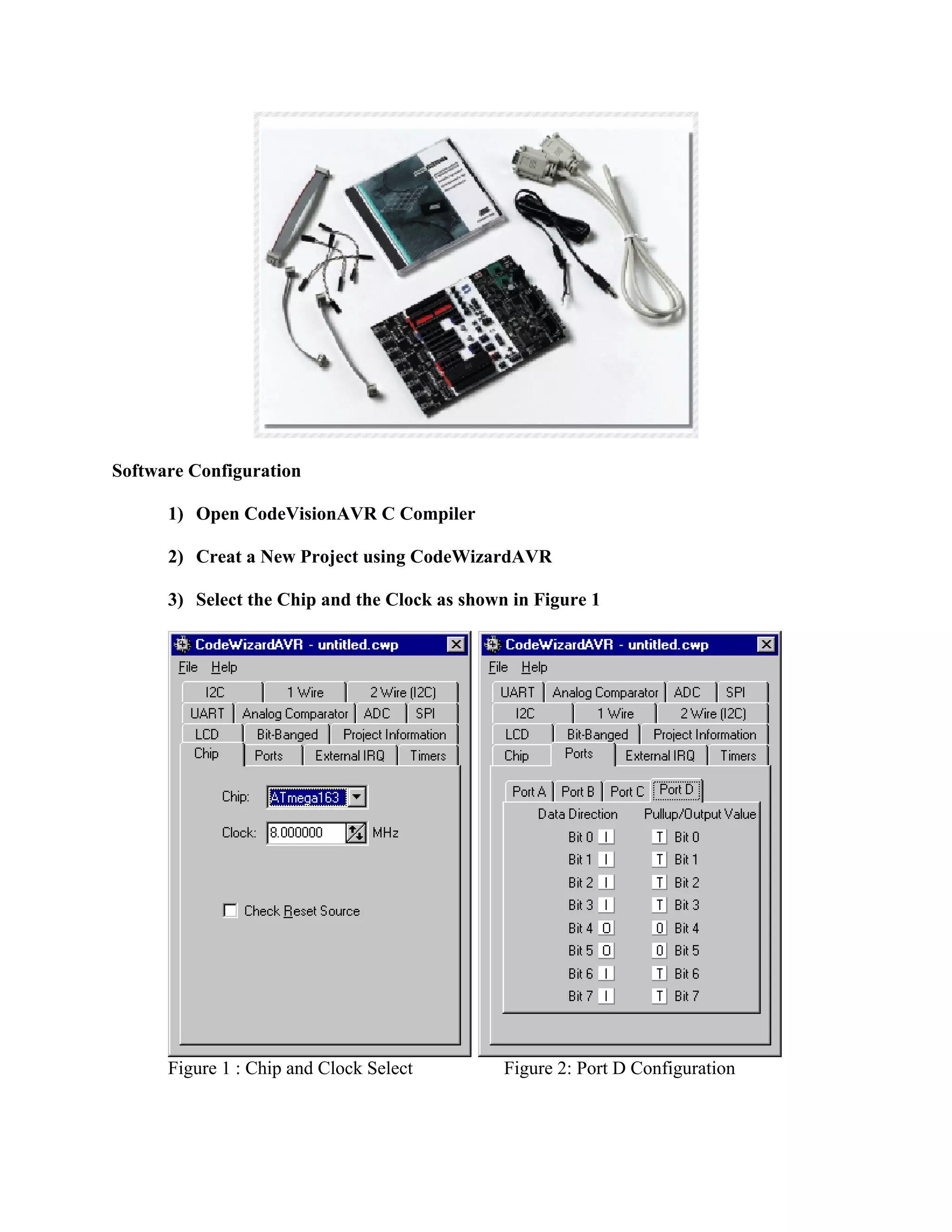
![// | s| x| x| x| x| x| x| x
// .
// |-2| 1|1/2|1/4|1/8|1/16|1/32|1/64
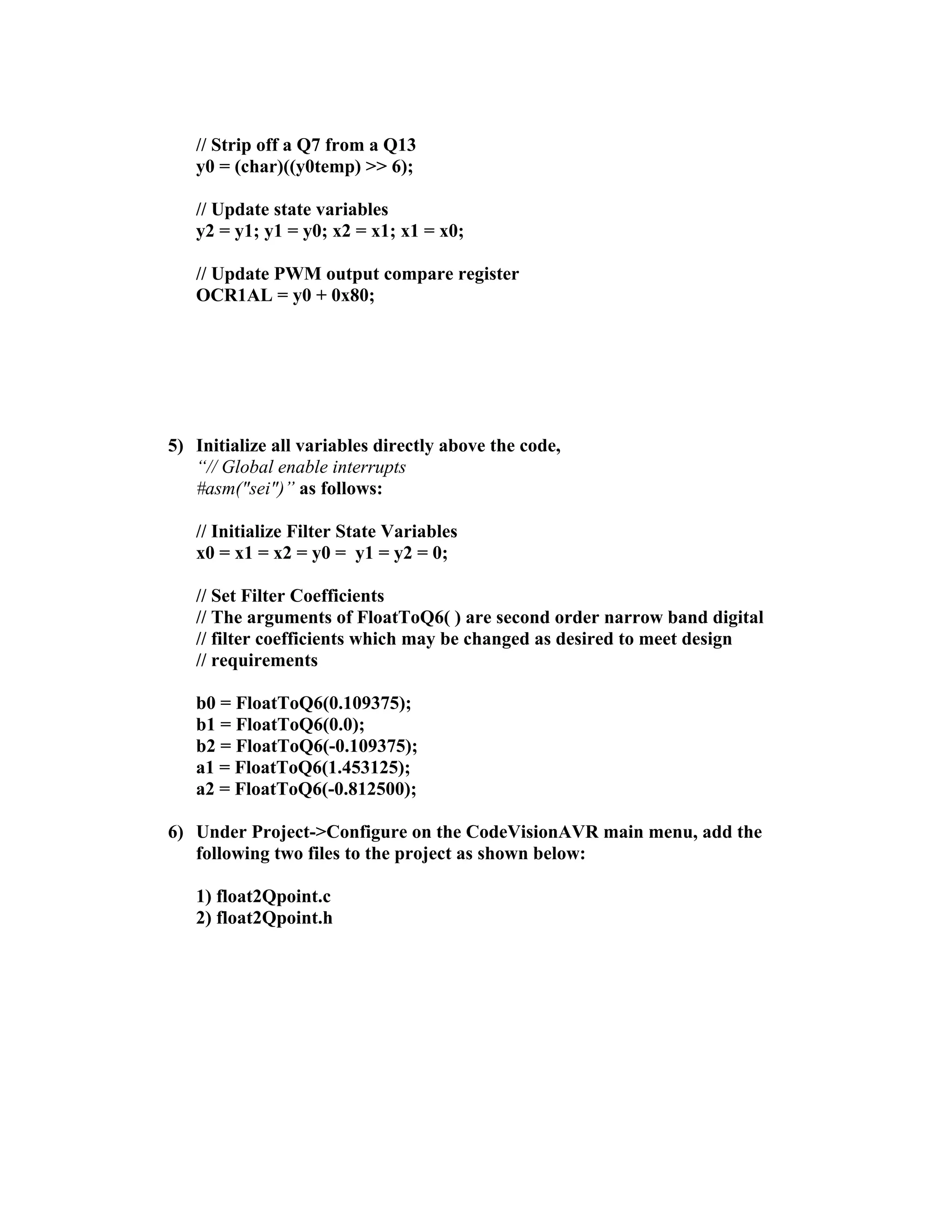
int y0temp; // Temporary 16 bit filter accumulation
// Filter multiply / accumulate result Variable is Q13 form
// Q13 can represent number from -4 to 4 - 1/8192
// Decimal place is between bits 13 and 14
// |s|x|x|x| x|x|x|x| x|x|x|x| x|x|x|x
// .
#define ADC_VREF_TYPE 0x20
// Read the 8 most semnificative bits
// of the ADC conversion result
unsigned char read_adc(unsigned char adc_input)
{
ADMUX=adc_input|ADC_VREF_TYPE;
ADCSR.6=1;
while (ADCSR.4==0);
ADCSR.4=1;
//return ADCW;
return ADCH;
}
// Timer 2 output compare interrupt service routine
interrupt [TIM2_COMP] void timer2_comp_isr(void)
{
// Place your code here
/*
unsigned int input; // input variable contains return from read_adc
input = read_adc(0); // read ad ch 0
PWM1DCReg = input>>8;
*/
// Read Analog Ch 0 & subtract half scale to remove "offset"
x0 = read_adc(0);
x0 = x0 - 0x80; // Subtract off DC offset
y0temp = (int)a1*y1 + (int)a2*y2 + (int)b0*x0 + (int)b1*x1 + (int)b2*x2; // Filter Multiply and
accumulate to Q13 Number
y0 = (char)((y0temp) >> 6);
// shift states
y2 = y1; y1 = y0; x2 = x1; x1 = x0;
PWM1DCReg = y0 + 0x80; // Add back DC offset and Update PWM register
PORTB = ~PORTB; // Toggle output port to allow measurement of ISR / Sampling Rate
}
// Declare your global variables here
void main(void)
{](https://image.slidesharecdn.com/dsp-onan-avr-101118213646-phpapp02/75/Dsp-on-an-avr-25-2048.jpg)
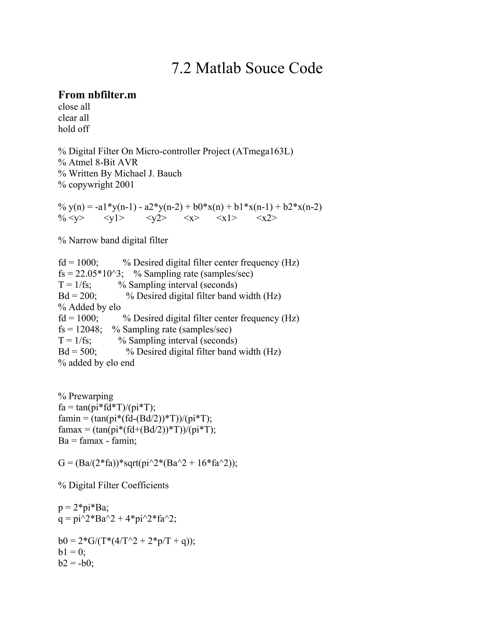
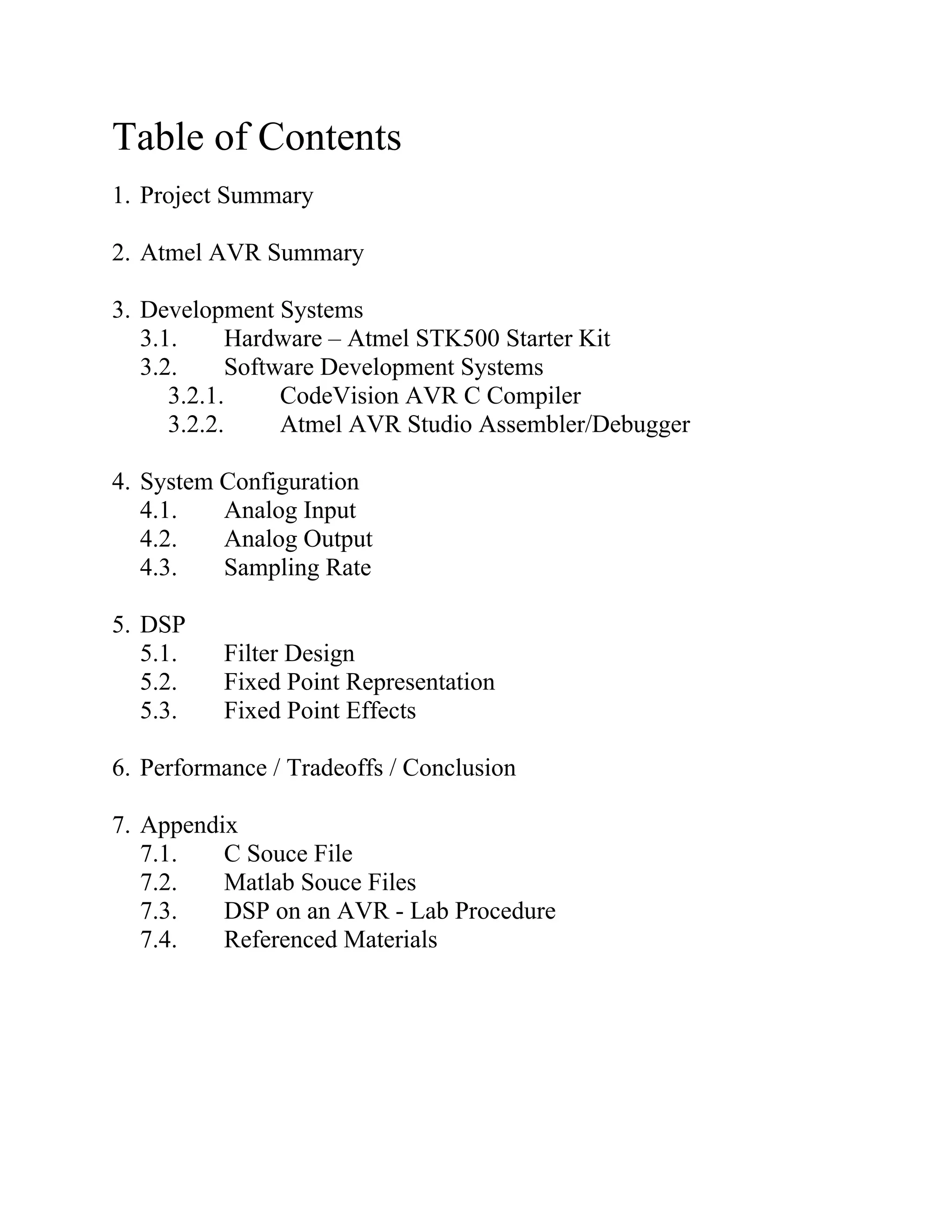
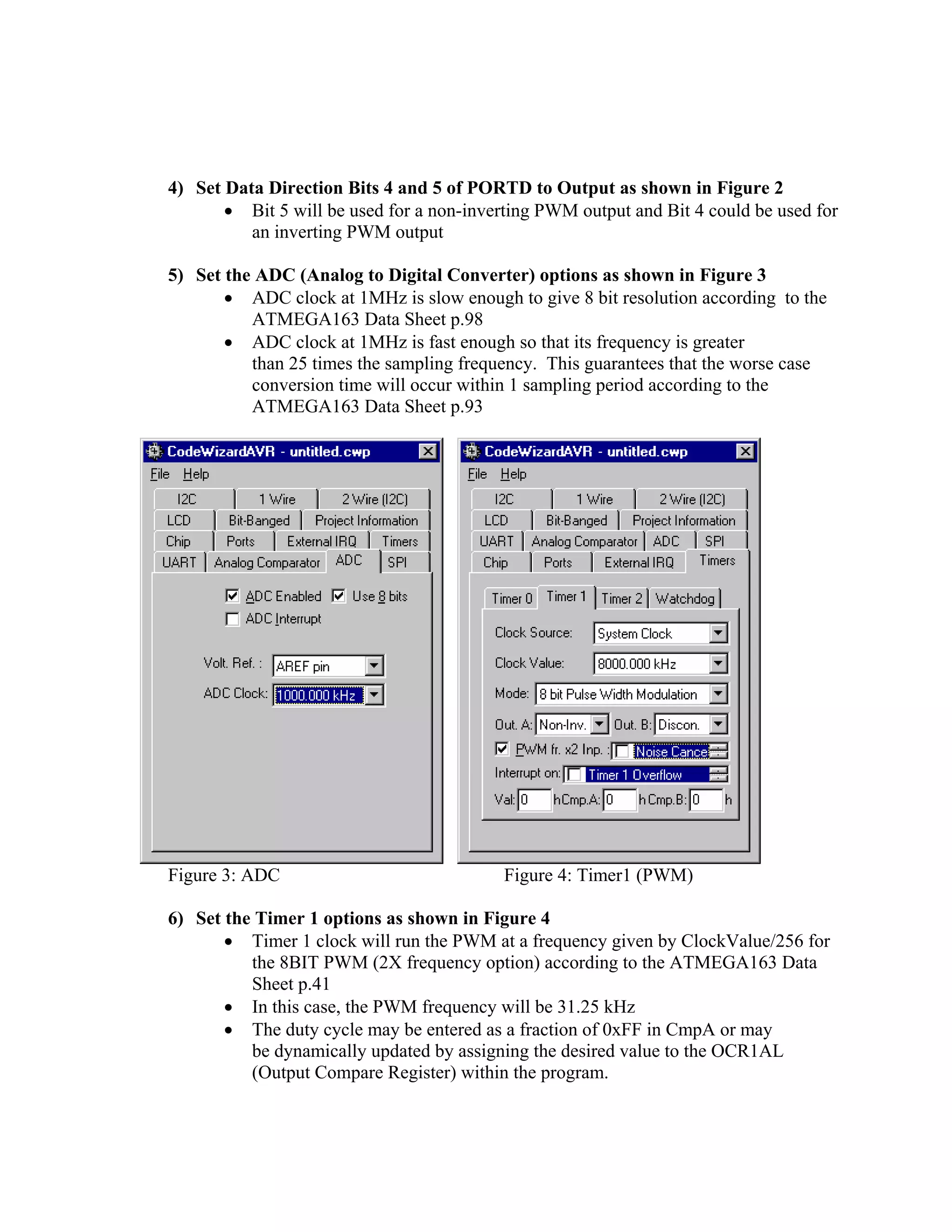
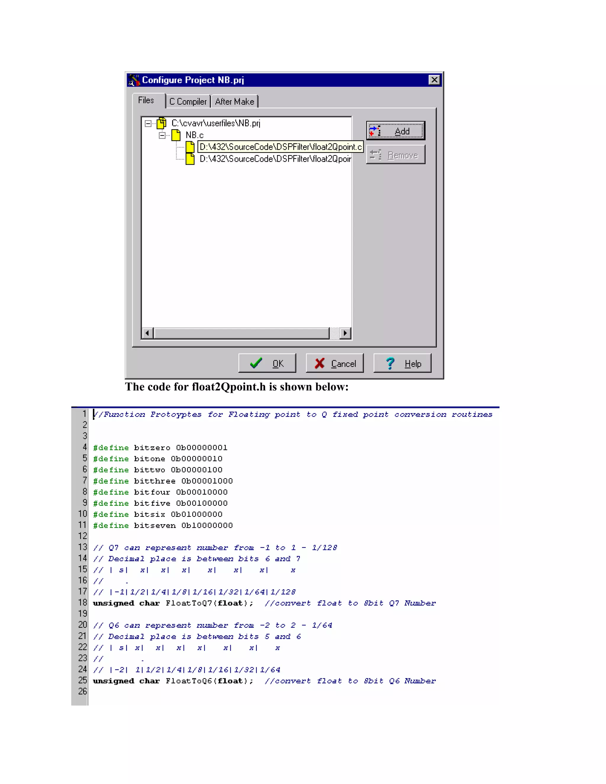
![a1 = (2*q - 8/T^2)/(4/T^2 + 2*p/T + q);
a2 = (4/T^2 - 2*p/T + q)/(4/T^2 + 2*p/T + q);
y1 = 0;
y2 = 0;
x1 = 0;
x2 = 0;
N = 1000; % Number of Samples
f = 1000; % Frequency of Sine Wave
n = 0:1:N;
t = n/fs;
x = sin(2*pi*f*n/fs);
for k=1:N+1
y(k) = -a1*y1 - a2*y2 + b0*x(k) + b1*x1 + b2*x2;
y2 = y1;
y1 = y(k);
x2 = x1;
x1 = x(k);
end
plot(t,x)
hold on
plot(t,y,'r')
% Frequency Response
figure(2)
[H,W,S] = freqz([b0 b1 b2],[1 a1 a2],1024,fs);
S.xunits = 'hz';
freqzplot(H,W,S);
From float2q6.m
% Written By Erick L. Oberstar
% University of Wisconsin Madison
% oberstar@cae.wisc.edu
% copywright 2001
function y = float2q6(x)
y = [0 0 0 0 0 0 0 0];
if (x<0)
y(1) = 1;](https://image.slidesharecdn.com/dsp-onan-avr-101118213646-phpapp02/75/Dsp-on-an-avr-30-2048.jpg)
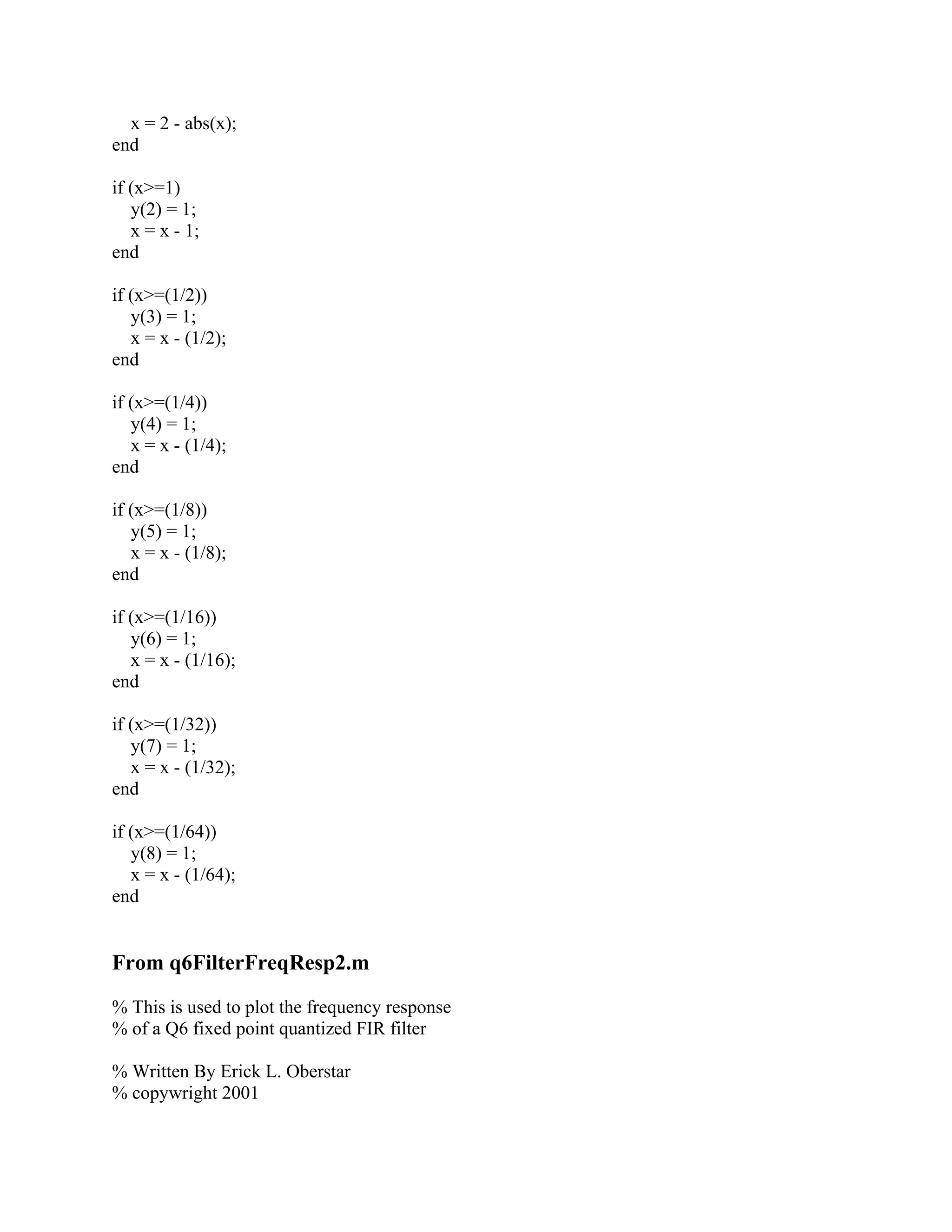
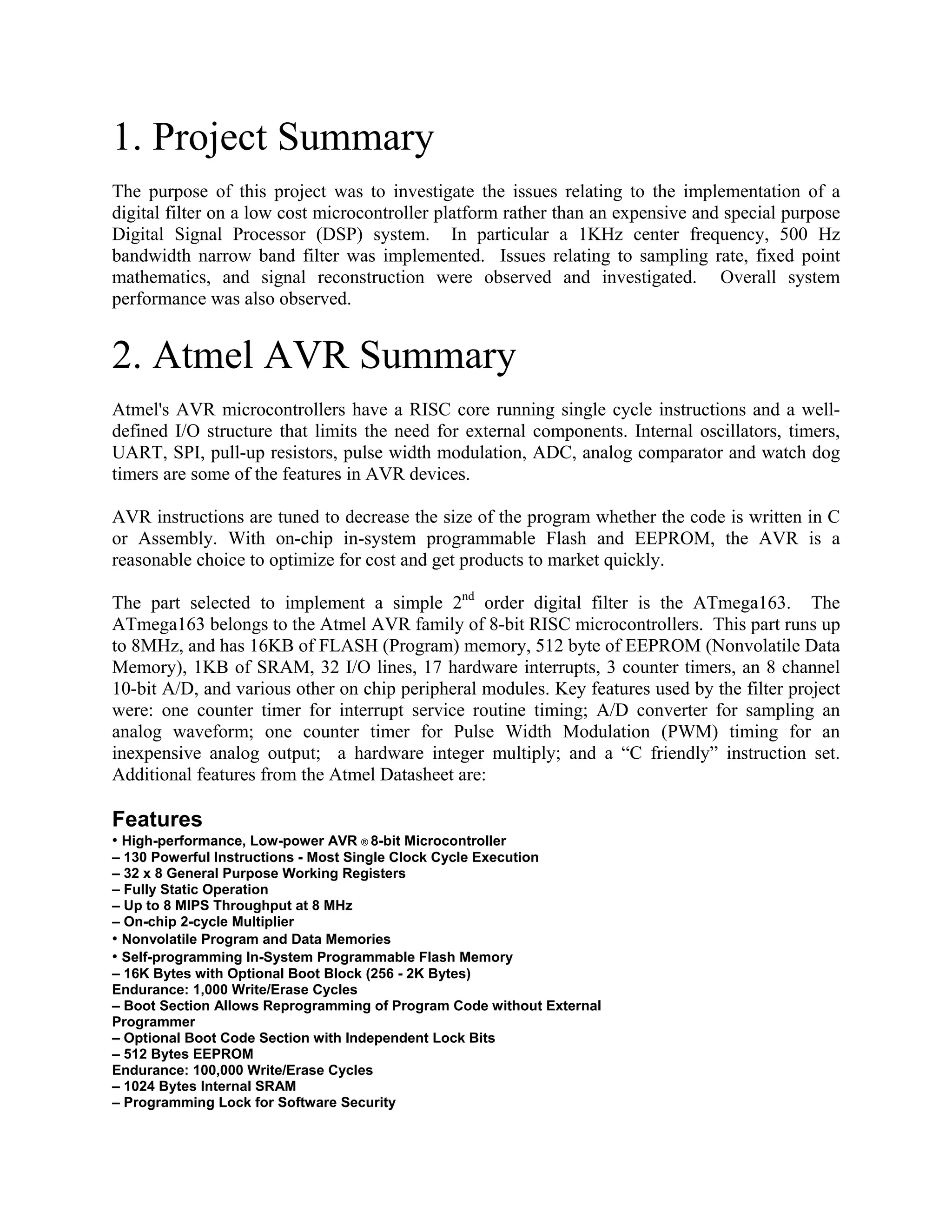
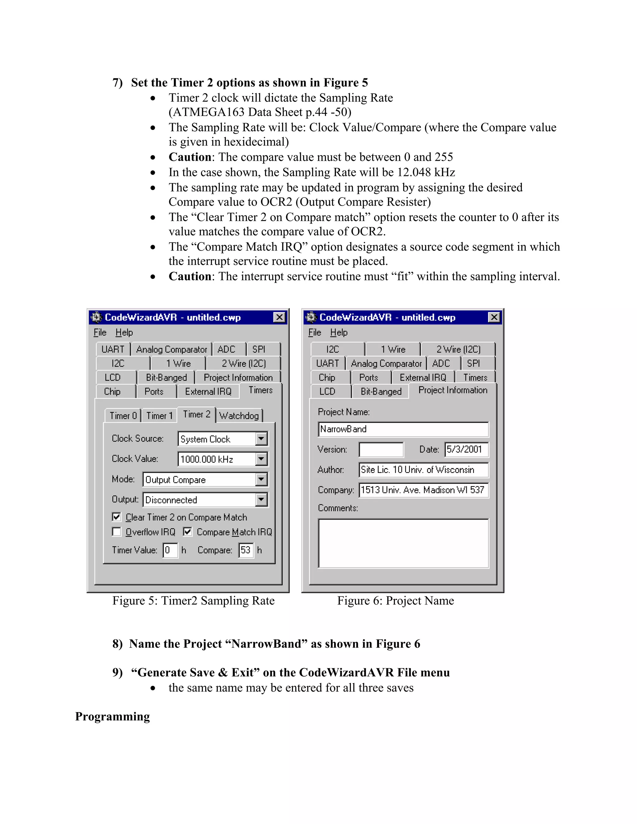
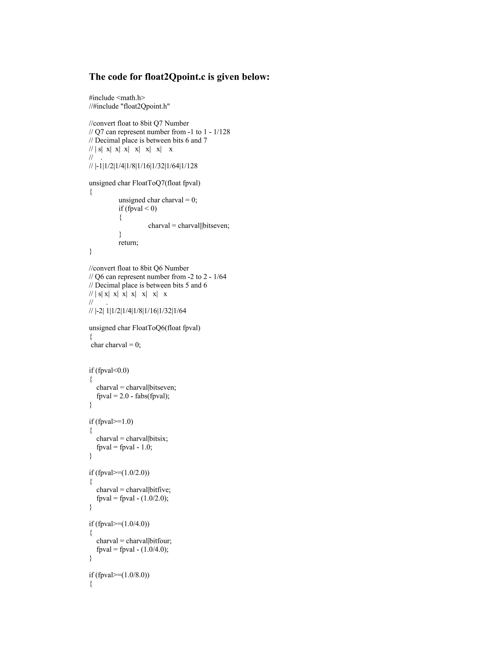
![%1KHz 500 HZ BW Bandpass Filter
figure(1)
% Ideal
% Coefficients from nbfilter.m
b0 = 0.11603539655267;
b1 = 0;
b2 = -0.11603539655267;
a1 = -1.51959288821994;
a2 = 0.76989749559855;
num = [b0 b1 b2]
den = [1 a1 a2]
fs = 12048
n = 256 %Number of points in frequency response
freqz(num,den,n,fs)
figure(2)
% fixed point effect on filter
b0 = .125 %0.11603539655267;
b1 = 0;
b2 = -.125 %-0.11603539655267;
a1 = -1.515625 %-1.51959288821994;
a2 = .765625 %0.76989749559855;
%b0 = 0.109375
%b2 = -0.109375
%a1 = -1.453125
%a2 = 0.812500
%a2 = .828125
num = [b0 b1 b2]
den = [1 a1 a2]
fs = 12048
n = 256 %Number of points in frequency response
freqz(num,den,n,fs)
%[h,f] = freqz(num,den,n,fs);
%freqzplot(h,f)](https://image.slidesharecdn.com/dsp-onan-avr-101118213646-phpapp02/75/Dsp-on-an-avr-32-2048.jpg)

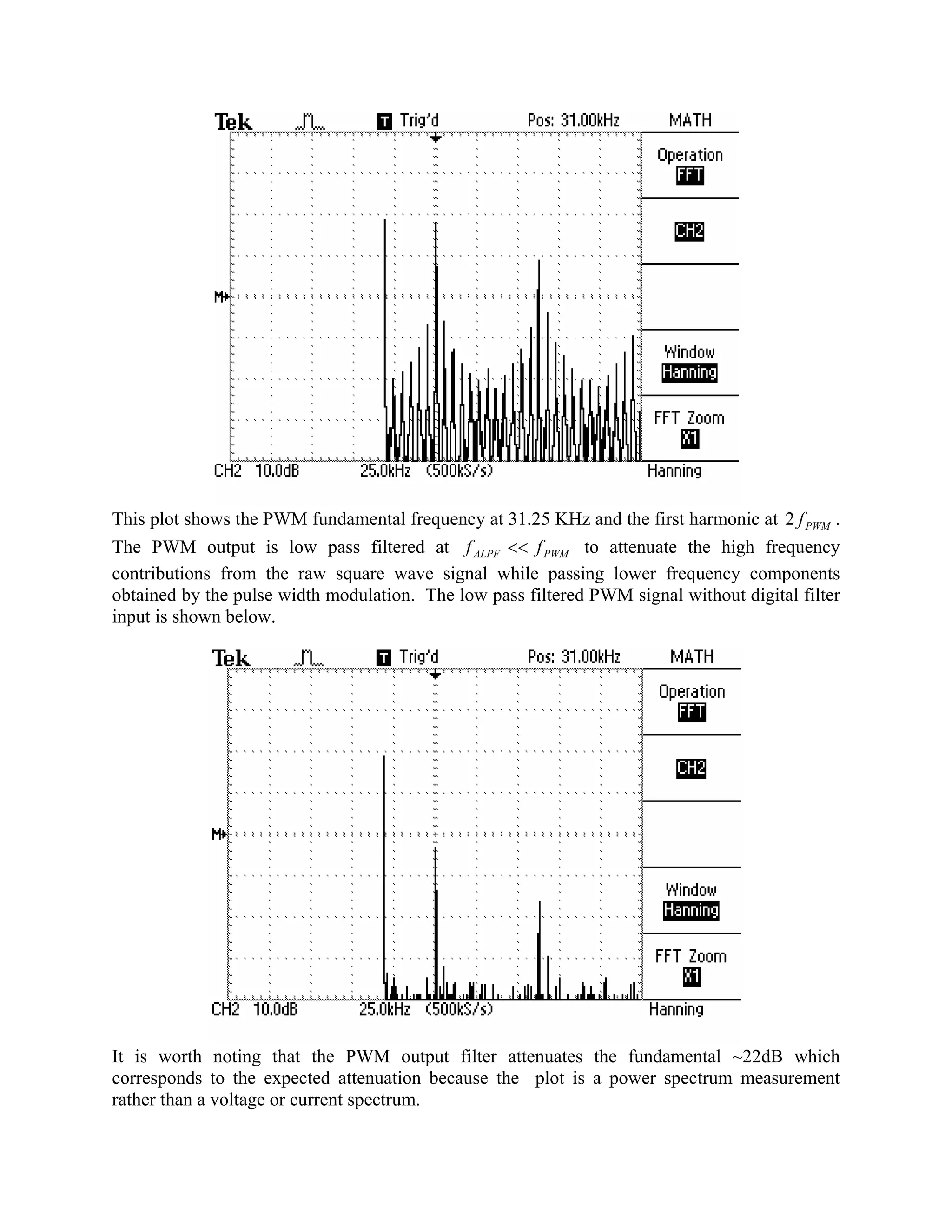
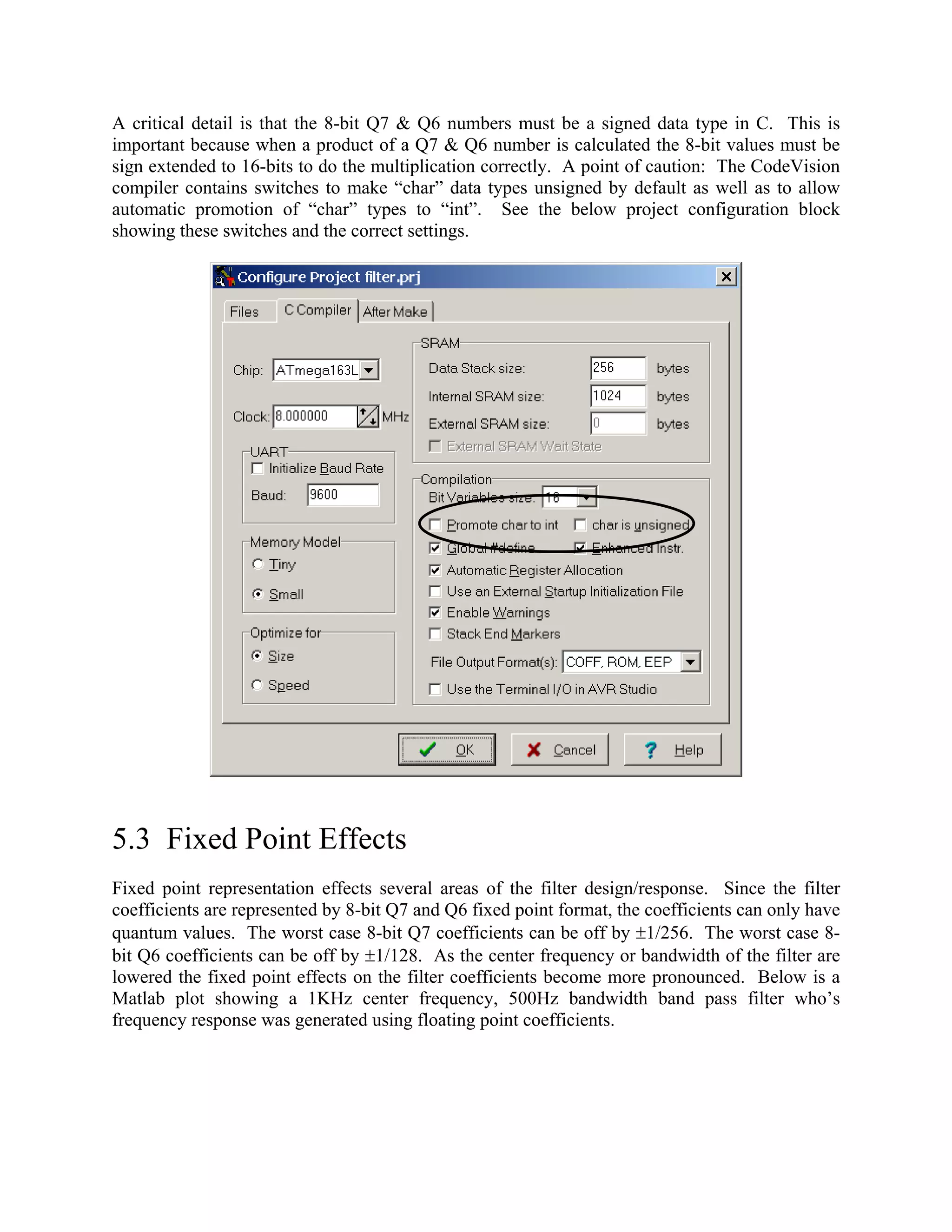
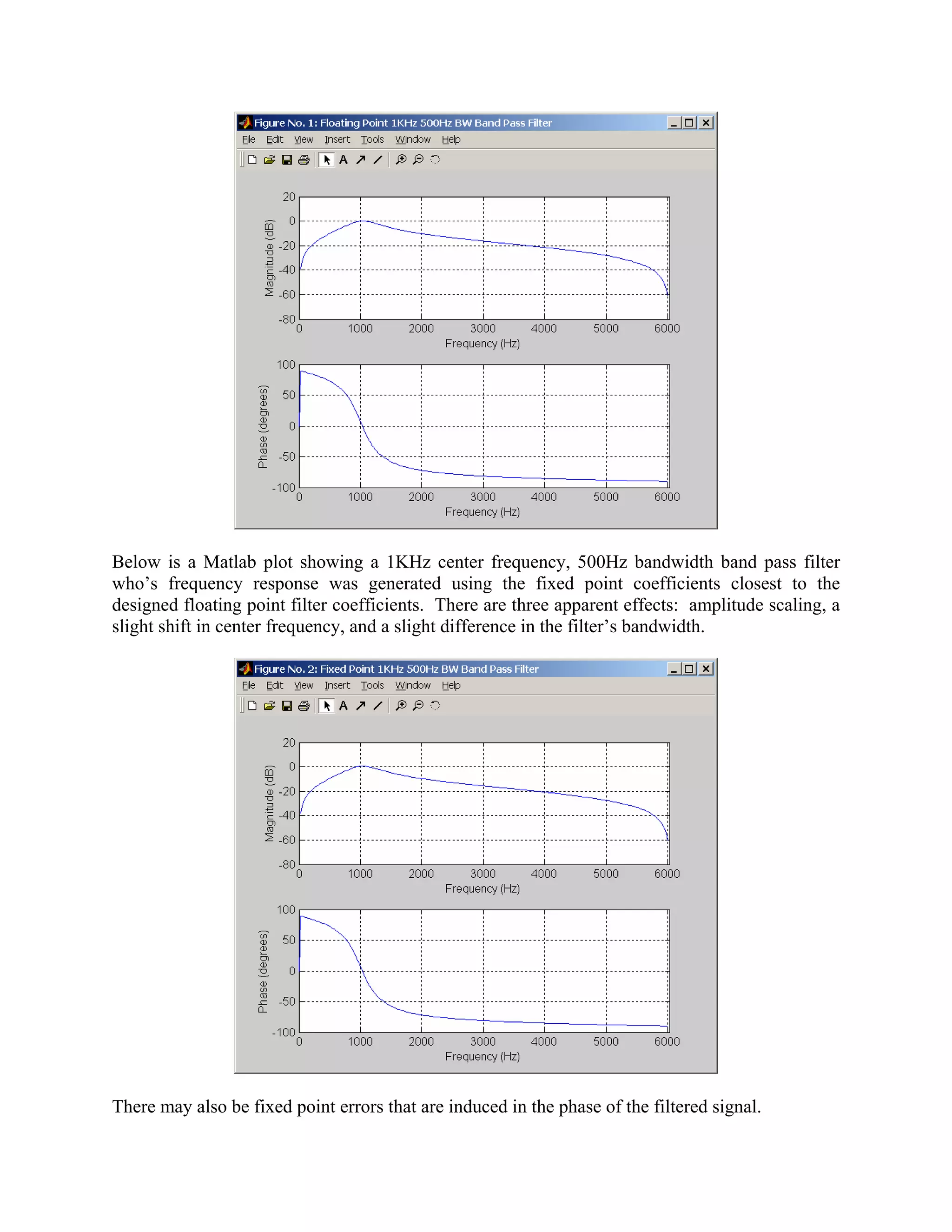
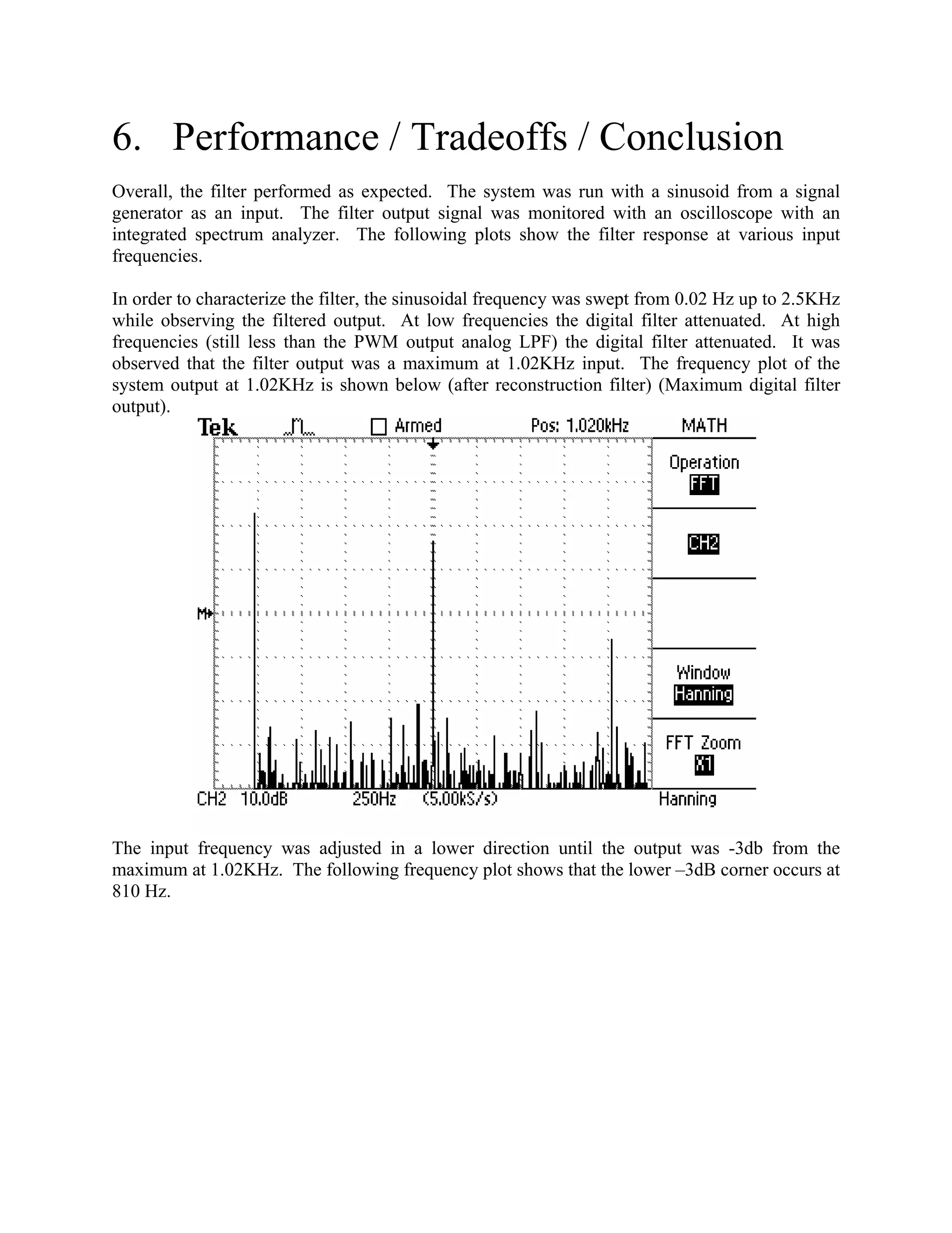
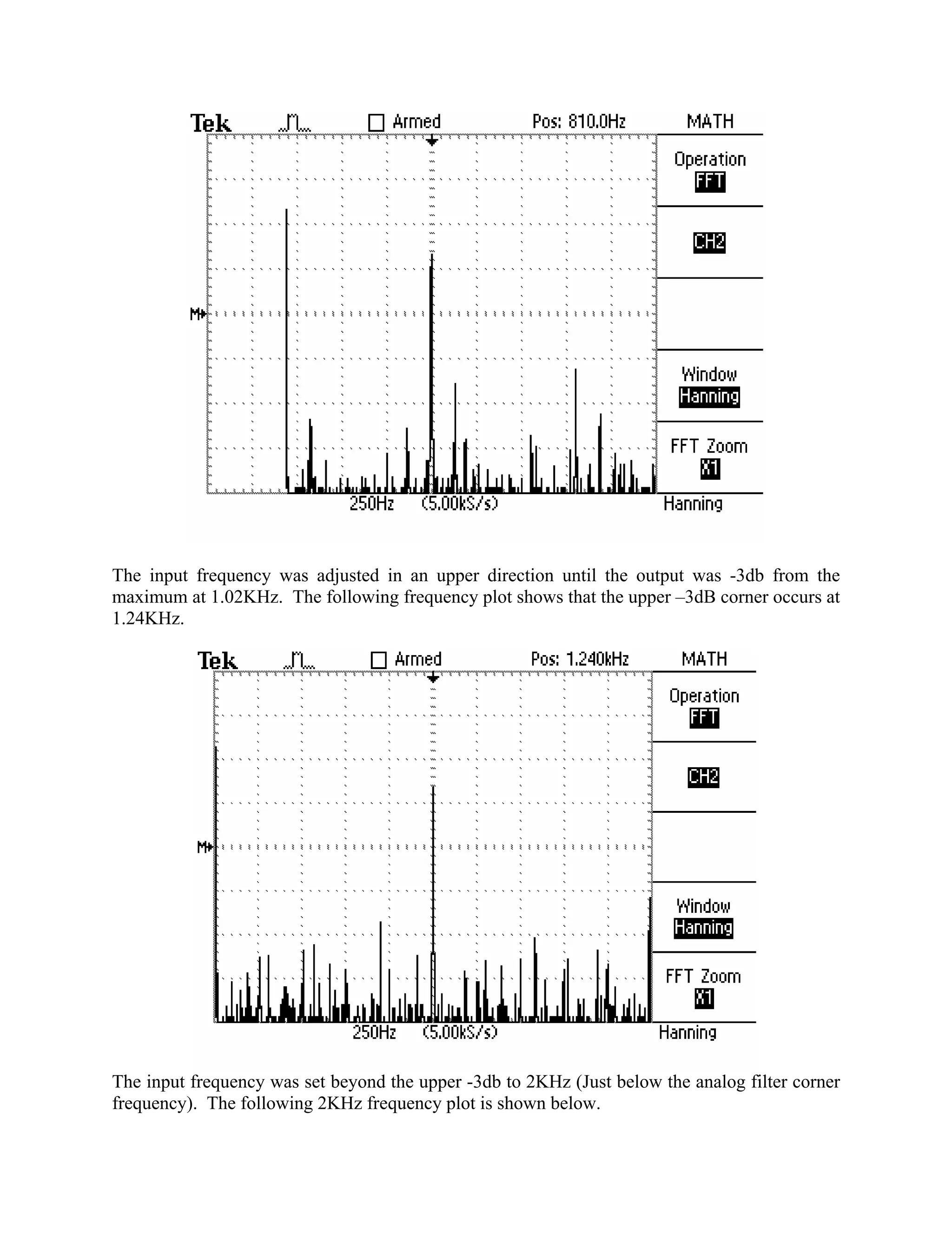
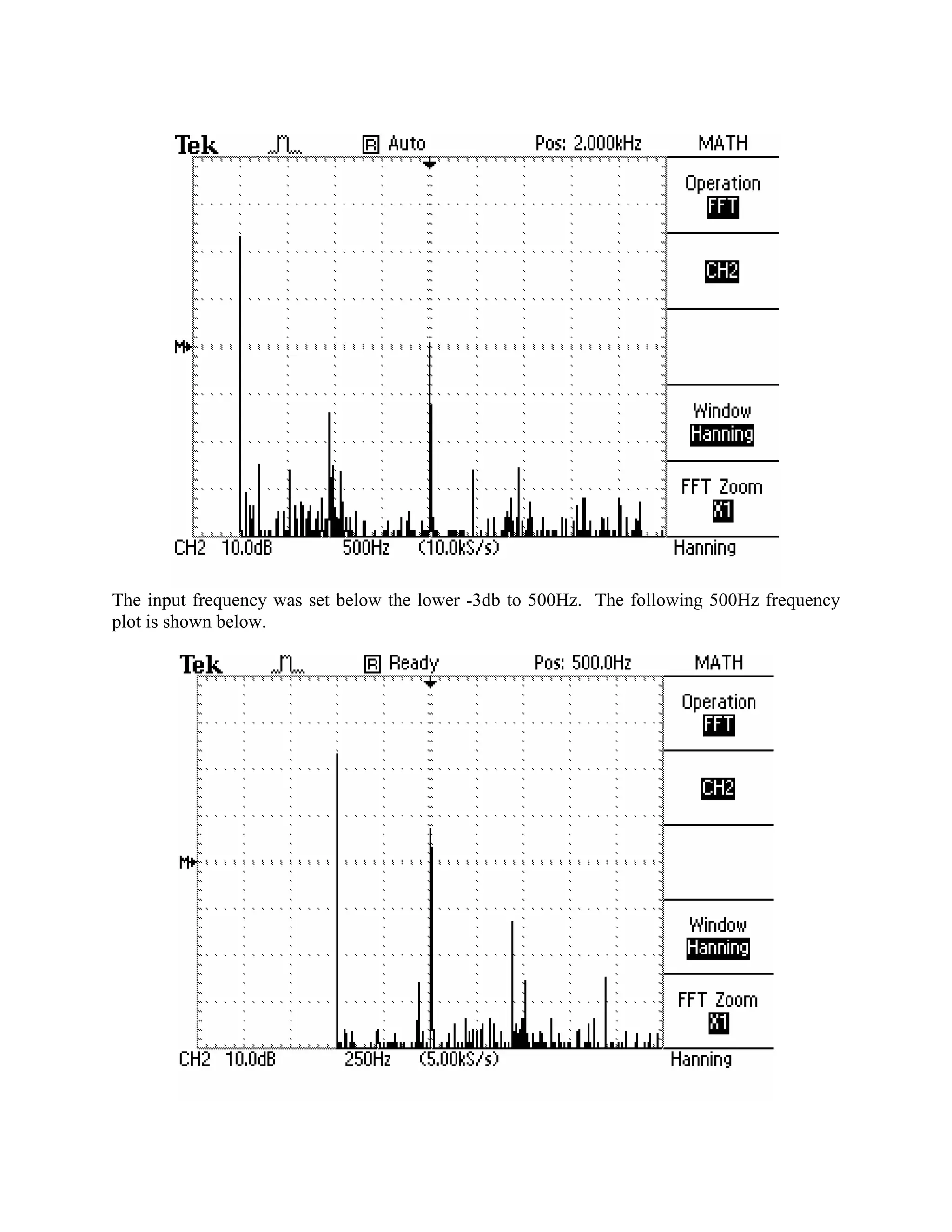
This document discusses the implementation of a narrow band digital filter on a low-cost microcontroller. It implemented a 1kHz center frequency, 500Hz bandwidth filter on an Atmel ATmega163 microcontroller. It describes the hardware and software tools used, including the Atmel STK500 starter kit, CodeVisionAVR C compiler, and Atmel AVR Studio. It discusses the analog input and output configurations, sampling rate, and filter design considerations like fixed-point representation effects. The performance and tradeoffs of the implementation are evaluated.