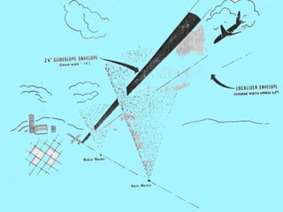
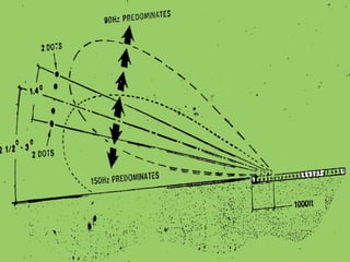
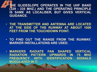
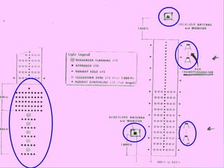
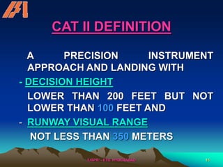
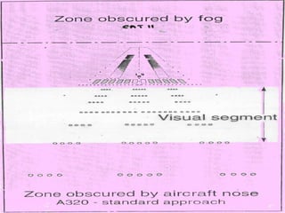
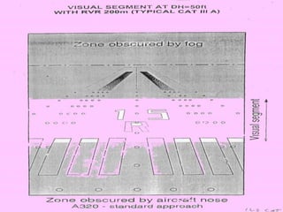
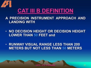
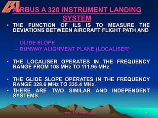
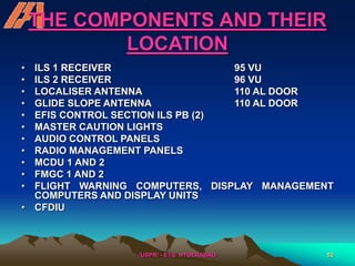
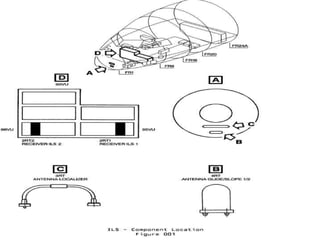
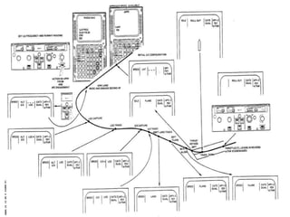
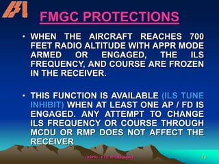
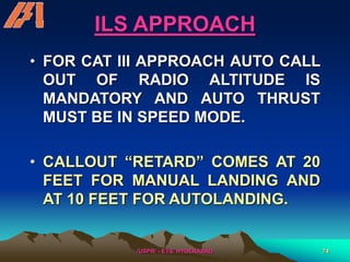
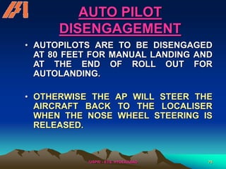
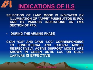
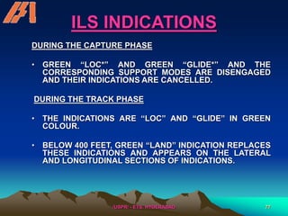
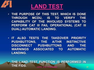
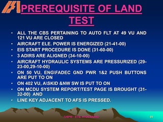
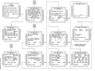
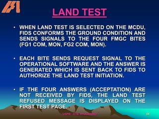
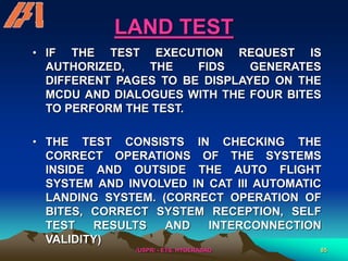
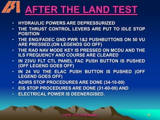
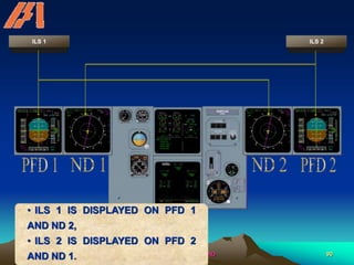
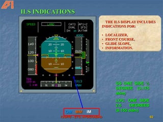
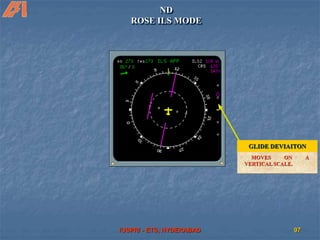
The document discusses the Instrument Landing System (ILS) used for landings in low visibility conditions. It describes the key components of the ILS including the localizer which defines the runway centerline and glide slope which defines the descent angle. It discusses different ILS categories (CAT I, II, III A,B,C) which allow landings at lower decision heights and visibility minimums. It also covers automatic landing systems, alert heights, visual references, transmissometers for measuring runway visual range and other technical details related to the ILS.
This document discusses the primary flight controls of aircraft:
1. The elevator controls pitch around the lateral axis using upward and downward deflection. Larger aircraft use hydraulic or electric systems.
2. The rudder controls yaw around the normal axis and is operated by rudder pedals, which also control steering while taxiing. Some aircraft with V-tails use linked ruddervator surfaces.
3. Ailerons control roll around the longitudinal axis and work differentially to bank the aircraft, sometimes assisted by differential rudder inputs to coordinate the turn. Some light aircraft use flaperons.
The document discusses the history and development of helicopters from the 15th century to the modern era. It covers early pioneers and their designs, including Da Vinci's concept of an aerial screw in 1483. Key developments include Sikorsky establishing records with counter-rotating coaxial rotors in 1909 and his VS-300 breaking records in 1939. The types of rotor systems are defined, including semi-rigid, fully articulated, and rigid rotors. Forces acting on the rotor like torque, gyroscopic precession, and coning are also summarized.
This document provides an overview of low visibility operations (LVO) including Category II, Category IIIA, and low visibility takeoffs. It defines key concepts such as decision height, runway visual range, operating minima, and requirements for aircraft, airfields, and flight crews to conduct these special operations. Category II allows for a manual landing at DH between 100-200 feet while Category IIIA requires an automatic landing system and has a DH under 100 feet or no DH with an RVR no less than 200 meters.
The document provides an overview of requirements for airworthiness management as per Part M, including:
1) The scope and extent of approval for a Continuing Airworthiness Management Organisation (CAMO), which includes developing maintenance programs and managing approvals.
2) Requirements for the Continuing Airworthiness Management Exposition (CAME) that specifies the CAMO's procedures and scope.
3) Requirements for facilities, personnel, and contracting maintenance to approved organisations.
4) Requirements for the CAMO's quality system to monitor compliance and ensure airworthy aircraft.
Takeoff and Landing | Flight Mechanics | GATE AerospaceAge of Aerospace
This document provides an overview of the topics covered in a presentation on flight mechanics, takeoff, and landing. The core topics include basics of atmosphere, aircraft classification, airplane configuration, flight instruments, aerodynamic forces, and airplane performance including takeoff, landing, climb, descent, stability, and equations of motion. The presentation will focus on takeoff and landing performance, outlining the different segments of ground roll for takeoff and approach/flare/ground roll distances for landing, as well as factors that influence accelerated performance like drag, minimum control speeds, and decision speeds. References for further information are provided.
This document discusses aircraft flight control systems. It describes three main categories of flight controls: primary, secondary, and auxiliary.
Primary flight controls include elevators, ailerons, and the rudder. Elevators control pitch, ailerons control roll, and the rudder controls yaw. Secondary flight controls include trim tabs which help balance aircraft control forces. Auxiliary controls include flaps and other high lift devices which allow aircraft to fly at slower speeds. The document provides details on how each of these various control surfaces and systems function.
This document describes aircraft flight control systems. It discusses the primary flight controls of elevators, ailerons, and rudders and how each control affects the aircraft's pitch, roll, and yaw. Secondary flight controls include trim tabs for stabilizing the elevators, ailerons, and rudder. Auxiliary controls are flaps and high-lift devices that increase an aircraft's lift during takeoff and landing. Flaps extend on the trailing edge of wings to increase their camber and reduce stall speed, while leading edge slats and spoilers disrupt airflow over wings.
This document provides information on different types of aircraft. It discusses the main categories of aircraft as being aerostats and aerodynes, with aerostats being lighter than air and aerodynes being heavier than air. It then describes various types of fixed wing aircraft, including those classified by number of wings (monoplane, biplane, triplane), wing position (low wing, mid wing, high wing), wing shape, tail configuration, and motion. It also discusses aerodynamic forces, control surfaces like flaps, ailerons, and elevators, as well as components like the fuselage and aerofoils. In summary, the document categorizes and describes different types of aircraft based on factors like
Este documento proporciona información sobre el formato y contenido del plan de vuelo IFR (Flight Plan). Explica cada una de las secciones del plan de vuelo, incluyendo información sobre el tipo de vuelo, aeronave, equipos, ruta, velocidad de crucero, aeropuertos de origen y destino, y otros detalles.
The Instrument Landing System (ILS) uses radio beams to guide aircraft during low visibility approaches and landings. ILS consists of ground-based transmitters that provide both horizontal and vertical guidance to aircraft. The localizer transmits left and right signals to guide aircraft horizontally along the runway centerline, while the glide path transmits upper and lower signals to guide aircraft vertically along the ideal descent glidepath. Onboard antennas and indicators in the cockpit allow pilots to follow the ILS beams for precise approaches down to decision heights as low as 200 feet during low visibility conditions.
This document provides an overview of aircraft landing gear systems. It describes three common types of landing gear: tricycle gear, taildragger gear, and ski gear. It then discusses key components of landing gear systems like nose wheel steering, shimmy damping systems, and safety systems. Nose wheel steering uses hydraulic power to turn the nose wheel. Shimmy damping systems like piston, vane, and steer types control unwanted vibration. Safety systems include mechanical downlocks, safety switches, and ground locks to prevent accidental gear retraction.
A ppt for a general introduction to the Electronic flight instrument system used in modern aircraft cockpits it may be helpful for Easa part 66 module preparation.....
The document provides information on the landing gear system of the Boeing 737 NG. It describes the main components and operation of the landing gear including:
- The aircraft has two main landing gears and a single nose gear.
- Hydraulic system A normally controls extension, retraction and nose wheel steering. System B provides alternatives.
- Extension and retraction are controlled by the landing gear lever and occur through hydraulic pressure and mechanical locks.
- Sensors monitor gear position and provide inputs to warning systems.
- Manual extension is possible if system A fails using gear releases.
Flight controls allow pilots to control the forces of flight and maneuver aircraft. This chapter focuses on basic flight control systems, from early mechanical systems to modern fly-by-wire designs. It describes the primary flight controls - ailerons, elevators, and rudders - and how they control roll, pitch, and yaw respectively. Adverse yaw created by ailerons is also discussed, as are methods to reduce it like differential ailerons. The chapter provides examples of different flight control configurations for various aircraft types.
Hands on experience with various type of tabsMayank Gupta
This document discusses different types of trim tabs used on aircraft. It describes the location of trim tabs on elevators, rudders, and ailerons. Elevator trim tabs help balance control forces and maintain the desired angle of attack, especially during slow flight. Elevator trim tab position determines whether the elevator is pushed up or down. Rudder and aileron trim tabs counter the effects of slipstream or an off-center center of gravity from uneven fuel levels or passenger weight. Types of trim tab systems include elevator trim tab systems and rudder trim tab systems.
Hardware assessment and validation are major parts of developing modern digital avionics systems. The assessment process involves fault tree analysis and failure mode effects analysis to evaluate reliability. Certification by regulatory authorities is also a key concern, particularly FAR Part 25.1309 which establishes requirements for equipment, systems, and installations to ensure safe flight. The document discusses factors like capability, reliability, maintainability, and cost that avionics systems must consider to receive certification.
The document provides guidelines for aircraft ground handling. It outlines minimum requirements including checking technical manuals, pre-briefing movements to discuss signals and responsibilities, and properly towing, parking, and securing aircraft. Ground handlers should be trained, move slowly and carefully, and reference technical manuals and unit standard operating procedures to safely maneuver aircraft on the ground.
1. An airfoil is the shape of a wing or blade that produces lift as air flows around it. It is inspired by the shape of a fish.
2. The key parts of an airfoil are the leading edge, which meets the air first, and the trailing edge, which smooths air flow.
3. NACA airfoils use a numbering system to describe characteristics like camber, thickness, and optimal lift coefficients. The 4-digit system describes camber, location of maximum camber, and thickness, while the 5-digit system provides more details.
The document summarizes radio navigation systems used in aircraft, including VOR (VHF Omni-directional Range) and ADF (Automatic Direction Finder). It describes how VOR uses ground-based transmitters to provide bearing information to aircraft's VOR receivers. It also explains how ADF uses non-directional beacon ground transmitters and an aircraft's loop antenna to determine bearing to the transmitter. The document provides details on components, signals, and evolution of displays for both navigation aids. It emphasizes the importance of installation, maintenance, and calibration of radio navigation avionics for safety of flight.
The document discusses aircraft performance certification and optimizing an aircraft's payload and range ability given physical and environmental limitations. It covers manufacturer's weight empty, operating empty weight, maximum zero fuel weight, maximum takeoff weight, and how payload and fuel affect an aircraft's range. Changing design aspects like maximum takeoff weight, zero fuel weight, and fuel capacity can impact the payload-range envelope.
This document provides an overview of the requirements for airfields to support low visibility operations including CAT II and CAT III approaches. It discusses runway characteristics such as width, slope, and markings. It also outlines the requirements for visual aids including lighting of runways, taxiways, approach lights, and signage. Finally, it addresses non-visual aids like ILS facilities and the protection of critical and sensitive areas, as well as obstacle clearance for ensuring safety during low visibility approaches and landings.
This document discusses the requirements and procedures for the initial climb phase of flight after takeoff. It is divided into four segments with different configurations, climb gradients, and speed requirements. Obstacle clearance must be ensured according to regulations specifying climb gradients and departure sector widths. The level-off height, flap settings, and use of flexible takeoff procedures can be adjusted to optimize climb performance based on factors like aircraft weight, temperature, and obstacle locations. Noise abatement procedures also specify speed and thrust profiles to reduce noise during initial climb.
This document discusses aircraft flight control systems. It describes the primary, secondary, and auxiliary flight controls, including the elevator, aileron, and rudder control systems, as well as secondary controls like trim tabs and auxiliary controls like flaps. It also provides details on how the autopilot system works, noting that it uses sensors, a gyroscope, and actuators to automatically control the aircraft without pilot input. The autopilot takes over complete control of the aircraft from take-off to landing.
The document provides information on anti-ice and rain protection systems for the Boeing 737 NG, including thermal anti-icing, electrical anti-icing, and windshield wipers. It describes the flight deck window heat, probe and sensor heat, engine anti-ice system, wing anti-ice system, ice detection system, and corresponding controls and indicators. The wing and engine anti-ice systems use bleed air to prevent ice buildup, while probes and sensors are heated electrically. Lights indicate system status and faults like overheat conditions.
Passengers are more and more demanding in terms of comfort. Therefore thermal comfort inside the cabin is more important.The state of mind, which expresses satisfaction with the thermal environment- ISO 7730
A large number of modern jet aircraft, of all sizes and including Very Light Jets (VLJs)s, routinely cruise at high altitudes.
The record of Accidents and Serious Incidents which have accompanied this increase in high altitude flight has suggested that pilot understanding of the aerodynamic principles which apply to safe high-altitude flight may not always have been sufficient. This applies particularly to attempts to recover from an unexpected loss of control. The subject is introduced in this article and covered in comprehensive detail in the references provided.
From a practical point of view, ‘high altitude’ operations are taken to be those above FL250, which is the altitude at above which aircraft certification requires that a passenger cabin overhead panel oxygen mask drop-down system has to be installed. Above this altitude a number of features begin to take on progressively more significance as altitude continues to increase:
There is a continued reduction in the range of airspeed over which an aircraft remains controllable;
True airspeed (TAS) (and therefore aircraft momentum) increases with altitude. However, the effectiveness of the aerodynamic controls and natural aerodynamic damping are both dependant upon indicated airspeed (IAS) and remain largely unchanged. Therefore, the ability of the aerodynamic flight controls to influence flight path or to recover from an upset is progressively reduced as altitude increases;
In the event of depressurisation, the time of useful consciousness for occupants deprived of oxygen reduces dramatically - see the separate articles on Emergency Depressurisation, and Hypoxia.
At very high altitude, occupants are exposed to slightly increased cosmic radiation. This is covered by the separate article "Cosmic Radiation".
This article focuses on aerodynamics and aircraft handling.
The document discusses various technologies used in air traffic control and air navigation, including navigation aids like VOR, ILS, DME, RNAV, and satellite navigation. It also covers flight planning, airport charts, approach charts, and the role of the flight management system.
Class G airspace has the fewest restrictions and is closest to the ground, while Class A airspace is the most restrictive and prohibits VFR flight. Each class has different pilot certification, equipment, and weather minimum requirements that become more stringent from Class G to Class A airspace. Special use airspaces also exist for security or military reasons and may impose additional limitations on aircraft. Knowledge of the national airspace system is essential for safe cross-country soaring flights.
This document provides information on ground maneuvering capabilities for the MD-90-30/-30ER aircraft, including:
- Turning radii for various nose gear steering angles, with notes that actual operating data may require more conservative maneuvers.
- Visibility from the cockpit in static position, including maximum aft vision and angles.
- Recommended runway and taxiway turn paths for turns over 90 degrees, 90 degrees, and within taxiways, with notes to consult airlines on operating procedures.
- Dimensions for a runway holding bay/apron, with minimum clearance distances between aircraft.
This document defines key distances related to aircraft takeoff and landing performance. It discusses:
- Screen height definitions for different aircraft types
- Definitions for runway, stopway, and clearway areas
- Declared distances including TORA, TODA, ASDA, and LDA that define available field lengths
- Required distances including TORR, TODR, and ASDR that must be met for safe takeoff and landing
- How to determine a balanced field length takeoff where TODR and ASDR are equal versus an unbalanced takeoff that takes advantage of a stopway or clearway.
FLIGHT INSPECTION of CNS FACILITIES [Compatibility Mode].pdfssuser1edd921
The document discusses flight inspection procedures for navigation aids. It describes the periodic ground and flight tests required by ICAO for radio navigation aids to ensure they are maintained within tolerance limits. The key types of inspections are commissioning, routine, special and site evaluation inspections. Flight inspection procedures are then outlined for localizers and glide paths, checking parameters like coverage, course width, clearance, structure and monitor alarms to ensure compliance with ICAO standards.
This document discusses various types of radar services used in air traffic control. It describes primary surveillance radar (PSR) which detects aircraft via reflected radio pulses, and secondary surveillance radar (SSR) which detects aircraft via transponder signals. SSR provides additional information like identification, altitude and speed. The objectives of radar services are improving airspace usage, reducing delays, and enhancing safety. Radar is used to provide area control services for enroute flights, approach control services within 50km of airports, and aerodrome control services at airports. Performance checks and identification procedures are discussed for maintaining radar separation standards between aircraft.
The Instrument Landing System (ILS) provides precision guidance to aircraft during instrument approaches and landings. It uses radio signals from an antenna array installed at the end of runways to provide lateral and vertical guidance. The ILS allows aircraft to land safely during low visibility conditions. It consists of localizer and glide slope components that guide the aircraft to the runway centerline and a 3 degree glide path for landing. Marker beacons also help pilots locate distances from the runway threshold. The ILS enables categories of instrument approaches with minimum visibility and decision height requirements.
The document discusses the design and operation of unmanned aerial vehicles (UAVs). It provides information on the scope and applications of UAVs, what constitutes an unmanned aerial system, different types of UAVs classified by range and endurance. It also describes the various subsystems of UAVs like payloads, communication systems, electric propulsion systems, autopilot systems. Finally, it provides details of the fixed wing UAV design project undertaken by the author, including design calculations and modeling using CAD software.
The document discusses the design and operation of unmanned aerial vehicles (UAVs). It describes the key components of UAVs including the aircraft, payloads, control stations and communication subsystems. It also discusses different types of UAVs such as fixed wing, quadcopter and hexacopter. The document outlines the design of an electric fixed wing UAV with a weight of 0.7kg, wingspan of 0.875m and wing area of 0.118m^2. It is powered by a 700W brushless electric motor and uses an ArduPilot autopilot system for autonomous flight capabilities.
This document discusses aerodrome operating minima, which establish weather limits for safe aeroplane operations at aerodromes. It defines categories for approaches and landings based on visibility, runway visual range (RVR), decision altitude/height (DA/H), and instrument approach procedures. It also addresses factors considered in calculating operating minima, such as aircraft type, approach lighting systems, and what to do if reported visibility drops below minimums. Restricted minima with increased visibility/RVR additives apply to non-scheduled and general aviation operators.
Airborne radar systems installed in aircraft can detect objects at long ranges and support air combat operations. There are four main types of airborne radar: radar altimeter to measure height above ground, weather radar to detect precipitation, terrain mapping radar, and ground moving target indication radar. Weather radar emits radio waves that reflect off rain droplets and snow crystals, displaying them in color-coded levels of reflectivity on the cockpit display. Pilots use controls to adjust the radar range, gain, and tilt to optimize weather detection and avoidance.
Runway overruns during landing are a major safety issue for commercial aviation. Airbus has developed the Runway Overrun Prevention System (ROPS) to help address this risk. ROPS uses avionics to continuously calculate the aircraft's landing distance and compare it to the remaining runway. It provides visual and audio alerts to pilots if a runway overrun is predicted. It can also automatically apply maximum braking if needed to help prevent an overrun. Airbus hopes making ROPS available globally will significantly reduce runway excursion accidents across the aviation industry.
RADAR is used for air traffic control and aircraft surveillance. It operates in the UHF and SHF bands using frequencies between 1-30 GHz. There are several types of RADAR used in aviation including en-route surveillance radar to track aircraft up to 300 NM, terminal approach radar for precision tracking near airports, and surface movement radar to monitor aircraft and vehicle movements on runways and taxiways. RADAR can use primary surveillance to detect aircraft via reflected pulses or secondary surveillance where aircraft transmit identification codes in response to interrogation signals.
The document provides procedures for flight inspection of CNS facilities. It describes pre-flight, in-flight, and post-flight inspection procedures. During pre-flight inspection, equipment is checked for readiness and NOTAMs are initiated. In-flight procedures involve understanding inspector messages and making transmitter, receiver and monitor adjustments as instructed. Post-flight includes saving transmitter data, conducting ground checks, and cancelling NOTAMs. The goal is to train personnel to competently assist with inspections and make proper adjustments under flight inspector guidance.
The document discusses the Air Data Inertial Reference System (ADIRS) on the Boeing 737 NG. The ADIRS contains two air data inertial reference units (ADIRUs) that each have an air data computer and inertial reference system. The ADIRS provides flight data like position, speed, altitude and attitude to other aircraft systems. It aligns using the aircraft's position, earth's rotation, and gravity to calculate latitude but not longitude.
This document discusses the various lighting systems used at airports to guide pilots and provide safety. It describes 9 key elements: airport beacon, approach lighting, threshold lighting, runway lighting including edge and centerline lights, PAPI lights, taxiway lighting, apron and hangar lighting, boundary lighting, and lighting for the wind direction indicator. For each element, it provides details on the purpose, configuration, colors used, and specifications to achieve standardization and ensure pilot guidance.
The document discusses air traffic control and services. It aims to prevent collisions between aircraft during flight and on the ground through separating aircraft laterally and longitudinally based on distance and time. It describes control areas like aerodromes and traffic zones. It also discusses flight level assignment, area navigation systems, routes and waypoints to guide aircraft along planned paths.
This document provides definitions and information about drones and unmanned aerial vehicles (UAVs). It discusses the components of typical drone systems, classifications of drones by range and size, latest trends including micro drones and payload developments, and examples of recent drone technologies from countries around the world like the Global Hawk, Predator, Harpy, and Camcopter.
topics covered are ASMGCS, HF transmitters an S-band radar. this ppt is useful for students who are taking summer training at Airports Authority of India.
- AMDAR is an automated aircraft-based observing system that is a component of WMO's WIGOS and GOS observing systems. It provides meteorological data from aircraft in near-real-time to NMHSs and for inclusion on the WMO GTS.
- AMDAR uses existing aircraft sensors and communications to collect parameters like wind, temperature, humidity, and turbulence. The data meets WMO requirements for accuracy and supports aviation operations and numerical weather prediction.
- The roles and responsibilities of the partners involved - WMO, NMHSs, airlines - are defined to establish AMDAR programs, ensure data quality, and maximize the benefits of the additional observations.
The Precision Approach Path Indicator (PAPI) provides visual guidance for pilots during approaches and landings. It uses a combination of red and white lights to indicate the aircraft's positioning relative to the ideal glidepath. The PAPI was developed to be more accurate than its predecessor, the VASI system. It generates lighting from a single wing bar rather than two longitudinal bars. In 1995, the PAPI was accepted internationally by ICAO as the standard visual approach indicator.
Electric vehicle and photovoltaic advanced roles in enhancing the financial p...IJECEIAES
Climate change's impact on the planet forced the United Nations and governments to promote green energies and electric transportation. The deployments of photovoltaic (PV) and electric vehicle (EV) systems gained stronger momentum due to their numerous advantages over fossil fuel types. The advantages go beyond sustainability to reach financial support and stability. The work in this paper introduces the hybrid system between PV and EV to support industrial and commercial plants. This paper covers the theoretical framework of the proposed hybrid system including the required equation to complete the cost analysis when PV and EV are present. In addition, the proposed design diagram which sets the priorities and requirements of the system is presented. The proposed approach allows setup to advance their power stability, especially during power outages. The presented information supports researchers and plant owners to complete the necessary analysis while promoting the deployment of clean energy. The result of a case study that represents a dairy milk farmer supports the theoretical works and highlights its advanced benefits to existing plants. The short return on investment of the proposed approach supports the paper's novelty approach for the sustainable electrical system. In addition, the proposed system allows for an isolated power setup without the need for a transmission line which enhances the safety of the electrical network
Discover the latest insights on Data Driven Maintenance with our comprehensive webinar presentation. Learn about traditional maintenance challenges, the right approach to utilizing data, and the benefits of adopting a Data Driven Maintenance strategy. Explore real-world examples, industry best practices, and innovative solutions like FMECA and the D3M model. This presentation, led by expert Jules Oudmans, is essential for asset owners looking to optimize their maintenance processes and leverage digital technologies for improved efficiency and performance. Download now to stay ahead in the evolving maintenance landscape.
Embedded machine learning-based road conditions and driving behavior monitoringIJECEIAES
Car accident rates have increased in recent years, resulting in losses in human lives, properties, and other financial costs. An embedded machine learning-based system is developed to address this critical issue. The system can monitor road conditions, detect driving patterns, and identify aggressive driving behaviors. The system is based on neural networks trained on a comprehensive dataset of driving events, driving styles, and road conditions. The system effectively detects potential risks and helps mitigate the frequency and impact of accidents. The primary goal is to ensure the safety of drivers and vehicles. Collecting data involved gathering information on three key road events: normal street and normal drive, speed bumps, circular yellow speed bumps, and three aggressive driving actions: sudden start, sudden stop, and sudden entry. The gathered data is processed and analyzed using a machine learning system designed for limited power and memory devices. The developed system resulted in 91.9% accuracy, 93.6% precision, and 92% recall. The achieved inference time on an Arduino Nano 33 BLE Sense with a 32-bit CPU running at 64 MHz is 34 ms and requires 2.6 kB peak RAM and 139.9 kB program flash memory, making it suitable for resource-constrained embedded systems.
artificial intelligence and data science contents.pptxGauravCar
What is artificial intelligence? Artificial intelligence is the ability of a computer or computer-controlled robot to perform tasks that are commonly associated with the intellectual processes characteristic of humans, such as the ability to reason.
› ...
Artificial intelligence (AI) | Definitio
The CBC machine is a common diagnostic tool used by doctors to measure a patient's red blood cell count, white blood cell count and platelet count. The machine uses a small sample of the patient's blood, which is then placed into special tubes and analyzed. The results of the analysis are then displayed on a screen for the doctor to review. The CBC machine is an important tool for diagnosing various conditions, such as anemia, infection and leukemia. It can also help to monitor a patient's response to treatment.
Batteries -Introduction – Types of Batteries – discharging and charging of battery - characteristics of battery –battery rating- various tests on battery- – Primary battery: silver button cell- Secondary battery :Ni-Cd battery-modern battery: lithium ion battery-maintenance of batteries-choices of batteries for electric vehicle applications.
Fuel Cells: Introduction- importance and classification of fuel cells - description, principle, components, applications of fuel cells: H2-O2 fuel cell, alkaline fuel cell, molten carbonate fuel cell and direct methanol fuel cells.
KuberTENes Birthday Bash Guadalajara - K8sGPT first impressionsVictor Morales
K8sGPT is a tool that analyzes and diagnoses Kubernetes clusters. This presentation was used to share the requirements and dependencies to deploy K8sGPT in a local environment.
Advanced control scheme of doubly fed induction generator for wind turbine us...IJECEIAES
This paper describes a speed control device for generating electrical energy on an electricity network based on the doubly fed induction generator (DFIG) used for wind power conversion systems. At first, a double-fed induction generator model was constructed. A control law is formulated to govern the flow of energy between the stator of a DFIG and the energy network using three types of controllers: proportional integral (PI), sliding mode controller (SMC) and second order sliding mode controller (SOSMC). Their different results in terms of power reference tracking, reaction to unexpected speed fluctuations, sensitivity to perturbations, and resilience against machine parameter alterations are compared. MATLAB/Simulink was used to conduct the simulations for the preceding study. Multiple simulations have shown very satisfying results, and the investigations demonstrate the efficacy and power-enhancing capabilities of the suggested control system.
Null Bangalore | Pentesters Approach to AWS IAMDivyanshu
#Abstract:
- Learn more about the real-world methods for auditing AWS IAM (Identity and Access Management) as a pentester. So let us proceed with a brief discussion of IAM as well as some typical misconfigurations and their potential exploits in order to reinforce the understanding of IAM security best practices.
- Gain actionable insights into AWS IAM policies and roles, using hands on approach.
#Prerequisites:
- Basic understanding of AWS services and architecture
- Familiarity with cloud security concepts
- Experience using the AWS Management Console or AWS CLI.
- For hands on lab create account on [killercoda.com](https://killercoda.com/cloudsecurity-scenario/)
# Scenario Covered:
- Basics of IAM in AWS
- Implementing IAM Policies with Least Privilege to Manage S3 Bucket
- Objective: Create an S3 bucket with least privilege IAM policy and validate access.
- Steps:
- Create S3 bucket.
- Attach least privilege policy to IAM user.
- Validate access.
- Exploiting IAM PassRole Misconfiguration
-Allows a user to pass a specific IAM role to an AWS service (ec2), typically used for service access delegation. Then exploit PassRole Misconfiguration granting unauthorized access to sensitive resources.
- Objective: Demonstrate how a PassRole misconfiguration can grant unauthorized access.
- Steps:
- Allow user to pass IAM role to EC2.
- Exploit misconfiguration for unauthorized access.
- Access sensitive resources.
- Exploiting IAM AssumeRole Misconfiguration with Overly Permissive Role
- An overly permissive IAM role configuration can lead to privilege escalation by creating a role with administrative privileges and allow a user to assume this role.
- Objective: Show how overly permissive IAM roles can lead to privilege escalation.
- Steps:
- Create role with administrative privileges.
- Allow user to assume the role.
- Perform administrative actions.
- Differentiation between PassRole vs AssumeRole
Try at [killercoda.com](https://killercoda.com/cloudsecurity-scenario/)
Software Engineering and Project Management - Introduction, Modeling Concepts...Prakhyath Rai
Introduction, Modeling Concepts and Class Modeling: What is Object orientation? What is OO development? OO Themes; Evidence for usefulness of OO development; OO modeling history. Modeling
as Design technique: Modeling, abstraction, The Three models. Class Modeling: Object and Class Concept, Link and associations concepts, Generalization and Inheritance, A sample class model, Navigation of class models, and UML diagrams
Building the Analysis Models: Requirement Analysis, Analysis Model Approaches, Data modeling Concepts, Object Oriented Analysis, Scenario-Based Modeling, Flow-Oriented Modeling, class Based Modeling, Creating a Behavioral Model.
2. /USPR/ - ETS, HYDERABAD 2
• LANDING IS AN IMPORTANT PHASE OF THE
FLIGHT.
• WHEN THE AIRCRAFT IS APPROACHING
THE AIRPORT, THE AIRCRAFT TAKES A
PATH IN LINE WITH THE RUNWAY AND FROM
A CERTAIN DISTANCE BEGINS TO DESCEND
UNTIL IT TOUCHES GROUND AT A POINT
NEAR THE RUNWAY THRESHOLD.
• WHEN THE VISIBILITY IS GOOD, WHETHER
IN A DAY OR NIGHT, THE LANDING IS
CARRIED OUT BY VISUAL OBSERVATION OF
RUNWAY MARKINGS AND RUNWAY LIGHTS.
3. /USPR/ - ETS, HYDERABAD 3
• THE LANDING IS THEN PERFORMED UNDER
VISUAL FLIGHT RULES (VFR) CONDITIONS.
• USUALLY THIS IS DONE WHEN THERE IS A
HORIZONTAL VISIBILITY OF ABOUT 5 KM
OR MORE AND THE VERTICAL VISIBILITY
OF 300 METERS OR MORE.
• WHEN THESE CONDITIONS ARE NOT
SATISFIED, THE LANDING IS DONE UNDER
INSTRUMENT FLIGHT RULES (IFR)
CONDITIONS.
4.
5. /USPR/ - ETS, HYDERABAD 5
• SPECIAL RADIO AIDS ARE LOCATED IN THE
AIRPORTS TO ENABLE THE AIRCRAFT TO
EXECUTE LANDINGS IN IFR CONDITIONS
UNDER BAD VISIBILITY.
• SUCH AIDS GIVE THE AIRCRAFT ITS EXACT
POSITION IN RELATION TO A DESIRED PATH
OF DESCENT.
• THIS MEANS THAT THE GUIDANCE
REGARDING THE DEVIATION OF THE
AIRCRAFT IN THE HORIZONTAL AND
VERTICAL PLANES IS GIVEN.
6. /USPR/ - ETS, HYDERABAD 6
• THE GUIDANCE GIVEN ARE LEFT / RIGHT
GUIDANCE WHICH HELPS THE AIRCRAFT
TO FOLLOW THE CENTERLINE OF THE
RUNWAY AND UP / DOWN GUIDANCE TO
FOLLOW A PARTICULAR GLIDE PATH FOR
SMOOTH TOUCH DOWN.
• THE INSTRUMENT LANDING SYSTEM
COMPRISES OF THE UNITS LOCALISER
AND GLIDE SLOPE.
• THE LOCALISER DEFINES THE CENTERLINE
OF THE RUNWAY AND THE GLIDESLOPE
DEFINES THE TOUCH DOWN ANGLE.
• THE INTERSECTION OF THESE TWO GIVES
THE APPROACH PATH.
9. /USPR/ - ETS, HYDERABAD 9
• THE LOCALISER OPERATES IN THE VHF BAND
(108 - 110 MHZ.) AND RADIATES TWO LOBES,
ONE WITH A PREDOMINANT MODULATION OF
90 HZ AND THE OTHER WITH A PREDOMINANT
MODULATION OF 150 HZ.
• ALONG THE CENTERLINE OF THE RUNWAY,
BOTH THE SIGNALS ARE EQUAL.
• THE LOCALISER TRANSMITTER AND ANTENNA
ARE LOCATED AT ABOUT 1000 FEET AT THE
OTHER END OF THE RUNWAY.
10. /USPR/ - ETS, HYDERABAD 10
• THE GLIDESLOPE OPERATES IN THE UHF BAND
(329 - 335 MHZ.) AND THE OPERATING PRINCIPLE
IS SAME AS LOCALISER, BUT GIVES VERTICAL
GUIDANCE.
• THE TRANSMITTER AND ANTENNA ARE LOCATED
AT THE SIDE OF THE RUNWAY AT ABOUT 1000
FEET FROM THE TOUCHDOWN POINT.
• TO FIND OUT THE RANGE FROM THE RUNWAY,
MARKER INSTALLATIONS ARE USED.
• MARKERS RADIATE FAN SHAPED VERTICAL
RADIATION PATTERN UPWARDS IN 75 MHZ
FREQUENCY WITH IDENTIFICATION SIGNALS
MODULATED IN IT.
11. /USPR/ - ETS, HYDERABAD 11
NEED FOR HIGHER CATEGORIES OF
INSTRUMENT LANDING SYSTEMS
• THE INSTRUMENT LANDING SYSTEMS INSTALLED
IN SOME OF THE AIRPORTS IN INDIA MEET THE
CATEGORY I LEVEL REQUIREMENTS.
• IN BAD WEATHER CONDITIONS, WHEN RVR IS
BELOW 600 METERS, AIRCRAFT CANNOT LAND OR
TAKE OFF USING SUCH AIRPORTS.
• HENCE, IT IS NECESSARY TO DEVELOP THE
CAPABILITY TO OPERATE FLIGHTS IN ALL
WEATHER CONDITIONS.
12. /USPR/ - ETS, HYDERABAD 12
DIFFERENT ASPECTS
INVOLVED IN ILS ARE
• AIRBORNE EQUIPMENT
• AIRCRAFT MAINTENANCE
• NON VISUAL AIDS (ILS FACILITY)
• VISUAL AIDS (RUNWAY MARKINGS AND
LIGHTING SYSTEMS)
• AIRFIELD MAINTENANCE
• ATC PROCEDURES and
• FLIGHT CREW PROCEDURES
15. /USPR/ - ETS, HYDERABAD 15
CAT II DEFINITION
A PRECISION INSTRUMENT
APPROACH AND LANDING WITH
- DECISION HEIGHT
LOWER THAN 200 FEET BUT NOT
LOWER THAN 100 FEET AND
- RUNWAY VISUAL RANGE
NOT LESS THAN 350 METERS
17. /USPR/ - ETS, HYDERABAD 17
CAT III A DEFINITION
A PRECISION INSTRUMENT APPROACH AND
LANDING WITH
• A DECISION HEIGHT
LOWER THAN 100 FEET BUT NOT LOWER
THAN 50 FEET AND
• RUNWAY VISUAL RANGE
NOT LESS THAN 200 METERS
19. /USPR/ - ETS, HYDERABAD 19
CAT III B DEFINITION
A PRECISION INSTRUMENT APPROACH AND
LANDING WITH
• NO DECISION HEIGHT OR DECISION HEIGHT
LOWER THAN 50 FEET and
• RUNWAY VISUAL RANGE LESS THAN 200
METERS BUT NOT LESS THAN 50 METERS
20. /USPR/ - ETS, HYDERABAD 20
CAT III C DEFINITION
A PRECISION INSTRUMENT
APPROACH AND LANDING WITH
• NO DECISION HEIGHT and
• NO RUNWAY VISUAL RANGE
LIMITATIONS
21. /USPR/ - ETS, HYDERABAD 21
AUTOMATIC LANDING SYSTEM
• AUTOMATIC LANDING SYSTEM IS
ONLY AN EQUIPMENT (OR GROUP OF
EQUIPMENT) PROVIDING AUTO
CONTROL OF THE AIRCRAFT DURING
APPROACH AND LANDING AND IT IS
NOT RELATED TO WEATHER
CONDITIONS.
22. /USPR/ - ETS, HYDERABAD 22
CAT II HAS OPTIONAL
AUTOLAND
• CAT II WEATHER MINIMA IS
ESTABLISHED TO PROVIDE
SUFFICIENT VISUAL REFERENCE AT
DH TO PERMIT A MANUAL LANDING.
• HOWEVER, AUTOMATIC LANDING
CAN ALSO BE DONE IN CAT II
23. /USPR/ - ETS, HYDERABAD 23
IN CAT III, AUTO LANDING IS
A MUST
• IN CAT III, WEATHER MINIMA DO NOT
PROVIDE SUFFICIENT VISUAL
REFERENCES TO ALLOW MANUAL
LANDING.
• THE MINIMA ONLY PERMIT THE PILOT TO
DECIDE TO LAND IN THE TOUCH DOWN
ZONE AND TO ENSURE SAFETY DURING
ROLL OUT.
• AS CAT III DOES NOT PROVIDE A
SUFFICIENT VISUAL REFERENCE,
AUTOMATIC LANDING SYSTEM IS
MANDATORY.
24. /USPR/ - ETS, HYDERABAD 24
DECISION HEIGHT
• DECISION HEIGHT IS THE SPECIFIED
HEIGHT IN THE PRECISION APPROACH, AT
WHICH A GO AROUND MUST BE INITIATED
UNLESS ADEQUATE VISUAL REFERENCE
HAS BEEN ESTABLISHED TO CONTINUE
THE APPROACH.
• DH IS MEASURED BY MEANS OF RADIO
ALTIMETER FOR CAT II / CAT III
OPERATIONS
26. /USPR/ - ETS, HYDERABAD 26
VISUAL REFERENCE
• THE REQUIRED VISUAL REFERENCE
MEANS, THE VISUAL AIDS OF THE SECTION
OF THE RUNWAY OR OF THE APPROACH
AREA, that means,
• FOR CAT II / CAT III OPERATIONS, A PILOT
MAY NOT CONTINUE APPROACH BELOW
DH, UNLESS A VISUAL REFERENCE
CONTAINING NOT LESS THAN THREE
SEGMENT OF THE ANY CATEGORY OF THE
LIGHTS IS OBTAINED.
27. /USPR/ - ETS, HYDERABAD 27
DECESION HEIGHT
• FOR CAT II OPERATIONS THE DH IS IN
BETWEEN 200 FEET AND 100 FEET.
• FOR CAT III OPERATIONS WITH DH,
THE DH IS IN BETWEEN 100 FEET AND
50 FEET.
• NORMALLY, THE DH MINIMUM IS
MENTIONED FOR REFERENCE
28. /USPR/ - ETS, HYDERABAD 28
ALERT HEIGHT
• ALERT HEIGHT IS THE HEIGHT
ABOVE THE RUNWAY, DEFINED FOR
CAT III OPERATIONS WITH FAIL
OPERATIONAL AUTOMATIC
LANDING SYSTEM.
• DH DEPENDS UPON VISIBILITY
CONDITIONS AND AH DEPENDS
UPON SERVICEABILITY OF
EQUIPMENT.
29. /USPR/ - ETS, HYDERABAD 29
ALERT HEIGHT
• ABOVE AH, A CAT III APPROACH WOULD
BE DISCONTINUED AND GO AROUND IS
INITIATED IF A FAILURE IS OCCURRED IN
ONE OF THE REDUNDANT PARTS OF THE
AUTOMATIC LANDING SYSTEM OR IN
THE RELEVANT GROUND EQUIPMENT.
• BELOW AH, APPROACH MAY BE
CONTINUED EXCEPT WHEN AUTO LAND
WARNING IS TRIGGERED
30. /USPR/ - ETS, HYDERABAD 30
FAIL OPERATIONAL AUTO
LANDING SYSTEM
• AN AUTOMATIC LANDING SYSTEM IS FAIL
OPERATIONAL, IF IN THE EVENT OF A
FAILURE BELOW ALERT HEIGHT, THE
REMAINING PART OF THE AUTOMATIC
LANDING SYSTEM ALLOWS THE AIRCRAFT
TO COMPLETE THE APPROACH, FLARE
AND LANDING
• IN AIRBUS A 320 AIRCRAFT, "CAT III DUAL"
IS FAIL OPERATIONAL LANDING SYSTEM.
31. /USPR/ - ETS, HYDERABAD 31
FAIL PASSIVE AUTO
LANDING SYSTEM
• IN THIS TYPE OF LANDING SYSTEM, IN THE EVENT
OF A FAILURE, THERE IS NO SIGNIFICANT
DEVIATION OF AIRCRAFT TRIM OR DEVIATION OF
FLIGHT PATH OR ATTITUDE, BUT THE LANDING IS
NOT COMPLETED AUTOMATICALLY.
• WITH THE FAIL PASSIVE AUTOMATIC LANDING
SYSTEM, THE PILOT ASSUMES CONTROL OF THE
AIRCRAFT AFTER A FAILURE.
• IN AIRBUS A 320 AIRCRAFT, "CAT III SINGLE" IS FAIL
PASSIVE AUTOMATIC LANDING SYSTEM.
32. /USPR/ - ETS, HYDERABAD 32
PROTECTION BY FMGC IN
A 320 AIRCRAFT
• BELOW 100 FEET RADIO ALTITUDE, THE
FMGC FREEZES THE LANDING CAPABILITY,
UNTIL LAND MODE IS DISENGAGED OR
BOTH AUTOPILOTS ARE OFF.
• THEREFORE, A FAILURE BELOW 100 FEET
DOES NOT CHANGE THE CATEGORY OF THE
LANDING SYSTEM
33. /USPR/ - ETS, HYDERABAD 33
RUNWAY VISUAL RANGE
• RVR IS THE RANGE OVER WHICH A PILOT
OF AN AIRCRAFT ON THE CENTERLINE OF
THE RUNWAY CAN SEE THE RUNWAY
SURFACE MARKINGS OR THE LIGHTS
DELINEATING THE RUNWAY OR
IDENTIFYING ITS CENTERLINE.
• CAT II / CAT III OPERATIONS REQUIRE
RAPIDLY UPDATED AND RELIABLE
REPORTS OF THE VISIBILITY CONDITIONS
WHICH A PILOT MAY EXPECT TO
ENCOUNTER IN THE TOUCHDOWN ZONE
AND ALONG THE RUNWAY.
35. /USPR/ - ETS, HYDERABAD 35
SLANT VISUAL RANGE (SVR)
• RVR IS NOT SLANT VISUAL RANGE (SVR).
SVR IS THE RANGE OVER WHICH A PILOT
OF AN AIRCRAFT IN THE FINAL STAGES OF
APPROACH OR LANDING CAN SEE THE
MARKINGS OR THE LIGHT ON THE RUNWAY.
• SVR IS NOT MEASURED AS THE PILOT
HIMSELF CAN SEE FROM THE HEIGHT.
38. /USPR/ - ETS, HYDERABAD 38
TRANSMISSOMETERS
• RVR MEASUREMENTS ARE
MEASURED BY A SYSTEM OF
CALIBRATED TRANSMISSOMETERS
AND IT ACCOUNTS FOR THE EFFECTS
OF AMBIENT LIGHT AND THE
INTENSITY OF RUNWAY LIGHTS.
40. /USPR/ - ETS, HYDERABAD 40
LOCATIONS OF
TRANSMISSOMETERS
• TRANSMISSOMETERS ARE STRATEGICALLY
LOCATED AND PROVIDE RVR MEASUREMENTS
ASSOCIATED WITH THREE BASIC PORTIONS OF
THE RUNWAY
• THE TOUCH DOWN ZONE (TDZ)
• THE MID RUNWAY PORTION (MID) AND
• THE ROLL OUT PORTION OR THE STOP END
41. /USPR/ - ETS, HYDERABAD 41
REQUIREMENTS OF RVRs
• FOR CAT II /CAT III A OPERATIONS
TOUCHDOWN ZONE RVR OR MID RVR
MEASUREMENT IS SUFFICIENT.
• BUT FOR CAT III B OPERATIONS, BOTH
TOUCHDOWN ZONE AND MID RVR ARE
MANDATORY AND ROLL OUT PORTION RVR
IS RECOMMENDATORY
42. /USPR/ - ETS, HYDERABAD 42
TRANSMISSOMETRS
INSTALLATION
• RVR DEFINITION CONSIDERS PILOT’S EYE
TO BE AT 15 FEET ABOVE THE RUNWAY
SURFACE. THE LIGHT PATH FROM THE
RUNWAY MARKINGS (AT 0 FEET) TO THE
PILOT’S EYE (15 FEET) HAS A MEAN HEIGHT
OF 7.5 FEET.
• HENCE, TRANSMISSIOMETERS ARE
LOCATED AT 6 TO 10 FEET HEIGHT ABOVE
THE RUNWAY.
43. /USPR/ - ETS, HYDERABAD 43
RUNWAY REQUIREMENTS
THE MARKINGS NECESSARY FOR CAT II / CAT
III OPERATIONS ARE
• RUNWAY CENTERLINE MARKINGS
• RUNWAY THRESHOLD MARKINGS
• TOUCHDOWN ZONE MARKINGS AND
• TAXI HOLDING POSITION MARKINGS
RUNWAY MARKINGS ARE WHITE IN COLOUR
TAXIWAY MARKINGS ARE YELLOW IN COLOUR
44. /USPR/ - ETS, HYDERABAD 44
VARIOUS LIGHTS INSTALLED
IN RUNWAYS
• RUNWAY THRESHOLD LIGHTS
• RUNWAY END LIGHTS
• RUNWAY EDGE LIGHTS
• RUNWAY CENTERLINE LIGHTS
• TOUCHDOWN ZONE LIGHTS
• APPROACH LIGHTS
• TAXIWAY CENTERLINE LIGHTS
• STOP BARS AND
• TAXI HOLDING POSITION LIGHTS
45. /USPR/ - ETS, HYDERABAD 45
INTERFERENCE TO ILS
SIGNALS
• ANY LARGE REFLECTING OBJECTS, INCLUDING
VEHICLES, AIRCRAFT AND FIXED STRUCTURES
WITHIN THE RADIATED SIGNAL COVERAGE, WILL
POTENTIALLY CAUSE INTERFERENCE TO ILS
SIGNALS.
• THE AREAS WITHIN WHICH DEGRADABLE
INTERFERENCE TO THE ILS SIGNALS OCCUR DUE
TO MOVEMENT ON THE GROUND IS DIVIDED INTO
TWO TYPES.
• ILS CRITICAL AREA AND ILS SENSITIVE AREA
47. /USPR/ - ETS, HYDERABAD 47
CRITICAL AREAS
• IT IS AN AREA OF DEFINED DIMENSIONS
ABOUT THE LOCALISER AND THE GLIDEPATH
ANTENNAS WHERE VEHICLES, INCLUDING
AIRCRAFT, ARE EXCLUDED DURING ALL ILS
OPERATIONS
• THE CRITICAL AREA IS PROTECTED
BECAUSE THE PRESENCE OF VEHICLES AND
/ OR AIRCRAFT INSIDE THESE BOUNDARIES
WILL CAUSE UNACCEPTABLE DISTURBANCE
TO THE ILS SIGNALS IN SPACE.
48. /USPR/ - ETS, HYDERABAD 48
SENSITIVE AREAS
• IT IS AN AREA EXTENDING BEYOND THE
CRITICAL AREA WHERE THE PARKING AND /
OR MOVEMENT OF VEHICLES, INCLUDING
AIRCRAFT IS CONTROLLED TO PREVENT
THE POSSIBILITY OF UNACCEPTABLE
INTERFERENCE TO THE ILS SIGNALS
DURING ILS OPERATIONS.
• THE SIZE OF A SENSITIVE AREA DEPENDS
UPON A NUMBER OF FACTORS INCLUDING
THE TYPE OF ILS ANTENNA, THE
TOPOGRAPHY AND THE SIZE AND
ORIENTATION OF MOVING OBJECTS.
49. /USPR/ - ETS, HYDERABAD 49
BETTER ANTENNAS
• MODERN DESIGNS OF LOCALISER
AND GLIDESLOPE ANTENNAS CAN BE
VERY EFFECTIVE IN REDUCING THE
DISTURBANCE POSSIBILITIES AND
HENCE THE EXTENT OF SENSITIVE
AREAS.
51. /USPR/ - ETS, HYDERABAD 51
AIRBUS A 320 INSTRUMENT LANDING
SYSTEM
• THE FUNCTION OF ILS IS TO MEASURE THE
DEVIATIONS BETWEEN AIRCRAFT FLIGHT PATH AND
– GLIDE SLOPE
– RUNWAY ALIGNMENT PLANE (LOCALISER)
• THE LOCALISER OPERATES IN THE FREQUENCY
RANGE FROM 108 MHz TO 111.95 MHz.
• THE GLIDE SLOPE OPERATES IN THE FREQUENCY
RANGE 328.6 MHz TO 335.4 MHz.
• THERE ARE TWO SIMILAR AND INDEPENDENT
SYSTEMS
52. /USPR/ - ETS, HYDERABAD 52
THE COMPONENTS AND THEIR
LOCATION
• ILS 1 RECEIVER 95 VU
• ILS 2 RECEIVER 96 VU
• LOCALISER ANTENNA 110 AL DOOR
• GLIDE SLOPE ANTENNA 110 AL DOOR
• EFIS CONTROL SECTION ILS PB (2)
• MASTER CAUTION LIGHTS
• AUDIO CONTROL PANELS
• RADIO MANAGEMENT PANELS
• MCDU 1 AND 2
• FMGC 1 AND 2
• FLIGHT WARNING COMPUTERS, DISPLAY MANAGEMENT
COMPUTERS AND DISPLAY UNITS
• CFDIU
54. /USPR/ - ETS, HYDERABAD 54
ANTENNAS
• LOCALISER ANTENNA
– THE ANTENNA IS CAPABLE OF RECEIVING IN THE
FREQUENCY RANGE OF 108 TO 112 MHz.
– IT IS A FOLDED HALF LOOP TYPE DRIVEN BY
CAPACITIVE COUPLING
– IT HAS TWO RF CONNECTORS USED TO FEED BOTH
ILS RECEIVERS ON ONE SIDE.
• GLIDE SLOPE ANTENNA
– THE ANTENNA IS CAPABLE OF RECEIVING IN THE
FREQUENCY RANGE OF 329 TO 335 MHz.
– THE TYPE OF THE ANTENNA IS SAME AS LOCALISER
ANTENNA
– IT HAS TWO INDEPENDENT CONNECTORS TO
CONNECT TO BOTH THE ILS RECEIVERS.
56. /USPR/ - ETS, HYDERABAD 56
ILS RECEIVER
• AT THE FACE OF THE RECIEVER, THERE
ARE THREE LEDs. THEY ARE ILS FAIL (RED),
ILS PASS (GREEN) AND DATA IN (RED) AND
A TEST SWITCH.
• ILS FAIL INDICATES INTERNAL FAILURE
• DATA IN INDICATES NO CONTROL INPUT OR
INCORRECT ARINC 429 INPUT FORMAT
• ILS PASS INDICATES THE SYSTEM IS O.K.
• BACK SIDE THERE ARE THREE
CONNECTORS FOR ATE INTERFACE,
SYSTEM INTERCONNECTIONS AND POWER
SUPPLY
58. /USPR/ - ETS, HYDERABAD 58
INSIDE THE RECEIVER
• THE ILS RECEIVER INCLUDES
– A LOCALISER TUNER
– A GLIDE SLOPE TUNER
– A BITE MODULE
– AN ILS MODULE
– A CPU MODULE
– A CPU MONITOR MODULE
– A DATA INTERFACE MODULE AND
– POWER SUPPLY MODULES
60. /USPR/ - ETS, HYDERABAD 60
LOCALISER TUNER
– IT RECEIVES AND DEMODULATES THE SIGNAL
FROM ONE OF THE 40 CHANNELS.
– IT INCLUDES A PRE SELECTOR
• TUNED TO SELECTED LOCALISER CHANNEL BY THE
TUNING VOLTAGE PROVIDED BY THE CPU MODULE
– MIXER
• SUBTRACTS THE LOCAL OSCILLATOR FREQUENCY FROM
THE PRESELECTOR LOCALISER SIGNAL TO PRODUCE
18.1 MHz IF SIGNAL.
– TWO IF AMPLIFIERS AND THE SECOND ONE IS A
THREE STAGE AMPLIFIER
– AN ENVELOPE DETECTOR, WHICH DETECTS THE
LOW FREQUENCY ENVELOPE OF THE RECEIVED
SIGNAL.
61. /USPR/ - ETS, HYDERABAD 61
GLIDE SLOPE TUNER
• IT RECEIVES AND DEMODULATES THE
SIGNALS FROM ONE OF THE 40 CHANNELS
AND COUPLED WITH THE LOCALISER
FREQUENCIES.
• IT HAS
– A PRESELECTOR
– A MIXER (IF IS 30.2 MHz)
– TWO IF AMPLIFIERS AND
– AN ENVELOPE DETECTOR
62. /USPR/ - ETS, HYDERABAD 62
BITE MODULE AND ILS MODULE
• BITE MODULE GENERATES 90 Hz AND
150 Hz TEST COMPOSITE SIGNALS
DURING THE TEST SEQUENCE.
• THE ILS MODULE PROCESSES THE
GLIDE SLOPE AND LOCALISER
COMPOSITE SIGNALS. ITS CIRCUITS
SEPARATE THE 90 Hz AND 150 Hz FROM
EACH COMPOSITE SIGNAL AND
GENERATES A DC VOLTAGE
PROPORTIONAL TO THE MODULATION
LEVEL OF EACH TONE.
63. /USPR/ - ETS, HYDERABAD 63
CPU MODULE AND CPU
MONITOR MODULE
• CPU MODULE PERFORMS THE PRIMARY CONTROL,
TIMING AND LOGIC COMPUTATIONS REQUIRED FOR
THE RECEIVER OPERATION (IT HAS A 80C85
MICROPROCESSOR)
• CPU MONITOR MODULE READS THE ANALOG
LOCALISER AND GLIDESLOPE TONES FROM THE ILS
MODULE, CONVERTS THEM INTO DIGITAL,
COMPUTES THE GLIDESLOPE AND LOCALISER
COURSE DEVIATION IN DDM AND COMPARES ITS
COMPUTATIONS WITH THE PRIMARY CPU
COMPUTATIONS TRANSMITTED ON THE ARINC 429
BUS.
64. /USPR/ - ETS, HYDERABAD 64
DATA INTERFACE AND POWER
SUPPLY MODULES
• DATA INTERFACE MODULE GIVES BOTHWAY ARINC 429
COMMUNICATION PATH BETWEEN RECEIVER, CONTROL
UNIT AND DISPLAY UNITS. IT ALSO RECEIVES THE
RECEIVER TUNING DATA AND CONTROL DISCRETES.
• THE POWER SUPPLY MODULE HAS TWO SUB MODULES.
– THE CONTROL MODULE WHICH HAS THE MAJOR RECTIFIER
ASSEMBLY AND
– OUTPUT MODULE WHICH DEVELOPES THE DC REGULATED
OUTPUTS FROM THE DC VOLTAGES SUPPLIED BY THE CONTROL
MODULE.
– IT DEVELOPS THE OUTPUTS + 5 VDC, +15 VDC, - 15 VDC AND +8
VDC
– A POWER MONITOR OUTPUT IS ALSO DEVELOPED AND APPLIED
TO A VOLTAGE CPMAPARATOR IN THE CPU MODULE.
66. /USPR/ - ETS, HYDERABAD 66
AIRBUS A320 AUTO LANDING
SYSTEM
THERE ARE TWO TYPES OF “APPROACH”
AVAILABLE IN A 320
• ILS APPROACH: (LAND MODE):
APPROACH IS PERFORMED ON THE ILS
BEAM (GLIDESLOPE AND LOCALISER)
• FMS APPROACH: GUIDANCE IS
PERFORMED FROM A THEORETICAL
PATH COMPUTED BY FMGC
68. /USPR/ - ETS, HYDERABAD 68
ILS APPROACH HAS THE
PRIORITY
• THE TYPE OF APPROACH IS SELECTED
THROUGH MCDU. THE SELECTION OF AN
ILS FREQUENCY ON RMP FORCES THE
SELECTION OF ILS APPROACH,
WHATEVER BE THE SELECTION MADE
ON MCDU
• ILS APPROACH CAN BE SELECTED IMPLICITLY
THROUGH FLIGHT PLAN DEFINITION OR
EXPLICITLY BY SELECTING A FREQUENCY AND
RUNWAY HEADING BY MEANS OF MCDU OR
RMP
69. /USPR/ - ETS, HYDERABAD 69
ILS APPROACH
• THE ILS MODE OF APPROACH PROVIDES
THE CAPTURE AND TRACK OF ILS BEAM
(LOC. AND GLIDE) AND ENSURES THE
FUNCTIONS ALIGNMENT, FLARE, AND
ROLL OUT
• ILS MODE IS AVAILABLE FOR THE AP
AND FD. IT ENABLES LANDINGS TO BE
PERFORMED FOR CAT III OPERATIONS
• THEREFORE, THE SELECTION OF LAND
MODE AUTHORIZES THE ENGAGEMENT
OF SECOND AP.
70. /USPR/ - ETS, HYDERABAD 70
ILS APPROACH
• THE ARMING OF LAND MODE BY APPR
PUSHBUTTON ON FCU ENABLES THE
LOC. AND GLIDE MODE TO BE ARMED IN
THE LATERAL AND LONGITUDINAL AXES.
• THE SUPPORT MODES ACTIVE IN THESE
AXES REMAIN ENGAGED UNTIL THE LOC
AND GLIDE BEAMS ARE CAPTURED.
• SWITCHING TO LOC. CPT AND G/S. CPT
MODES OCCURS WHEN THE CAPTURE
CONDITIONS ARE MET.
71. /USPR/ - ETS, HYDERABAD 71
ILS APPROACH
• WHEN THE AIRCRAFT IS STABILIZED ON
THE LOC. AND GLIDE BEAMS, THE LOC.
TRACK AND GLIDE TRACK MODES ARE
ACTIVATED.
• THE AP / FD GUIDES THE AIRCRAFT
ALONG THE ILS BEAM TO 30 FEET.
• AT THIS ALTITUDE, THE LAND MODE
PROVIDES THE ALIGNMENT ON THE
RUNWAY CENTERLINE ON THE YAW AXIS
AND FLARE ON THE PITCH AXIS.
72. /USPR/ - ETS, HYDERABAD 72
ILS APPROACH
• THE LAND TRACK MODE HAS TWO SUB
MODES, ALIGN AND ROLL OUT
• ALIGN MODE ENGAGES PROVIDED BOTH
FACS ARE OPERATIONAL. BELOW 100
FEET, LOSS OF FACS DOES NOT CAUSE
AP / FD DISENGAGEMENT OR LOSS OF
LAND TRACK MODE.
• ROLL OUT SUB MODE IS ENGAGED AT
TOUCHDOWN AND PROVIDES GUIDANCE
ON THE RUNWAY CENTERLINE.
73. /USPR/ - ETS, HYDERABAD 73
FMGC PROTECTIONS
• WHEN THE AIRCRAFT REACHES 700
FEET RADIO ALTITUDE WITH APPR MODE
ARMED OR ENGAGED, THE ILS
FREQUENCY, AND COURSE ARE FROZEN
IN THE RECEIVER.
• THIS FUNCTION IS AVAILABLE (ILS TUNE
INHIBIT) WHEN AT LEAST ONE AP / FD IS
ENGAGED. ANY ATTEMPT TO CHANGE
ILS FREQUENCY OR COURSE THROUGH
MCDU OR RMP DOES NOT AFFECT THE
RECEIVER
74. /USPR/ - ETS, HYDERABAD 74
ILS APPROACH
• FOR CAT III APPROACH AUTO CALL
OUT OF RADIO ALTITUDE IS
MANDATORY AND AUTO THRUST
MUST BE IN SPEED MODE.
• CALLOUT “RETARD” COMES AT 20
FEET FOR MANUAL LANDING AND
AT 10 FEET FOR AUTOLANDING.
75. /USPR/ - ETS, HYDERABAD 75
AUTO PILOT
DISENGAGEMENT
• AUTOPILOTS ARE TO BE DISENGAGED
AT 80 FEET FOR MANUAL LANDING AND
AT THE END OF ROLL OUT FOR
AUTOLANDING.
• OTHERWISE THE AP WILL STEER THE
AIRCRAFT BACK TO THE LOCALISER
WHEN THE NOSE WHEEL STEERING IS
RELEASED.
76. /USPR/ - ETS, HYDERABAD 76
INDICATIONS OF ILS
SELECTION OF LAND MODE IS INDICATED BY
ILLUMINATION OF “APPR” PUSHBUTTON IN FCU
AND BY VARIOUS INDICATIONS ON FMA
SECTION OF PFD.
• DURING THE ARMING PHASE
CYAN “G/S” AND CYAN “LOC” CORRESPONDING
TO LONGITUDINAL AND LATERAL MODES
RESPECTIVELY. ACTIVE SUPPORT MODES ARE
SHOWN IN GREEN UNTIL LOC OR GLIDE
CAPTURE IS EFFECTIVE
77. /USPR/ - ETS, HYDERABAD 77
ILS INDICATIONS
DURING THE CAPTURE PHASE
• GREEN “LOC*” AND GREEN “GLIDE*” AND THE
CORRESPONDING SUPPORT MODES ARE DISENGAGED
AND THEIR INDICATIONS ARE CANCELLED.
DURING THE TRACK PHASE
• THE INDICATIONS ARE “LOC” AND “GLIDE” IN GREEN
COLOUR.
• BELOW 400 FEET, GREEN “LAND” INDICATION REPLACES
THESE INDICATIONS AND APPEARS ON THE LATERAL
AND LONGITUDINAL SECTIONS OF INDICATIONS.
78. /USPR/ - ETS, HYDERABAD 78
ILS INDICATIONS
DURING FLARE PHASE
• THE GREEN “LAND” INDICATION IS REPLACED BY GREEN
“FLARE” INDICATION
DURING ROLL OUT PHASE
• GREEN “ROLL OUT” INDICATION REPLACES THE
“FLARE” INDICATION.
• IN ADDITION, THE LANDING CAPABILITY IS DISPLAYED
ON THE PFD, AS SOON AS LAND MODE IS SELECTED AS “
CAT 1, CAT 2, CAT 3 SINGLE, CAT 3 DUAL”
80. /USPR/ - ETS, HYDERABAD 80
LAND TEST
• THE PURPOSE OF THIS TEST, WHICH IS DONE
THROUGH MCDU, IS TO VERIFY THE
CAPABILITY OF THE INVOLVED SYSTEMS TO
PERFORM CAT III FAIL OPERATIONAL (CAT III
DUAL) AUTOMATIC LANDING.
• IT ALSO TESTS THE TAKEOVER PRIORITY
PUSHBUTTONS, THE A/THR INSTINCTIVE
DISCONNECT PUSHBUTTONS AND THE
WARNINGS ASSOCIATED TO AUTOMATIC
LANDING.
• THE LAND TEST FUNCTION IS PERFORMED IN
THE FIDS.
81. /USPR/ - ETS, HYDERABAD 81
PREREQUISITE OF LAND
TEST
• ALL THE CBS PERTAINING TO AUTO FLT AT 49 VU AND
121 VU ARE CLOSED
• AIRCRAFT ELE. POWER IS ENERGIZED (21-41-00)
• EIS START PROCEDURE IS DONE (31-60-00)
• 3 ADIRS ARE ALIGNED (34-10-00)
• AIRCRAFT HYDRAULIC SYSTEMS ARE PRESSURIZED (29-
23-00,29-10-00)
• ON 50 VU, ENGFADEC GND PWR 1&2 PUSH BUTTONS
ARE PUT TO ON
• ON 402 VU, ASKID &NW SW IS PUT TO ON
• ON MCDU SYSTEM REPORT/TEST PAGE IS BROUGHT (31-
32-00) AND
• LINE KEY ADJACENT TO AFS IS PRESSED.
84. /USPR/ - ETS, HYDERABAD 84
LAND TEST
• WHEN LAND TEST IS SELECTED ON THE MCDU,
FIDS CONFORMS THE GROUND CONDITION AND
SENDS SIGNALS TO THE FOUR FMGC BITES
(FG1 COM, MON, FG2 COM, MON).
• EACH BITE SENDS REQUEST SIGNAL TO THE
OPERATIONAL SOFTWARE AND THE ANSWER IS
GENERATED WHICH IS SENT BACK TO FIDS TO
AUTHORIZE THE LAND TEST INITIATION.
• IF THE FOUR ANSWERS (ACCEPTATION) ARE
NOT RECEIVED BY FIDS, THE LAND TEST
REFUSED MESSAGE IS DISPLAYED ON THE
FIRST TEST PAGE.
85. /USPR/ - ETS, HYDERABAD 85
LAND TEST
• IF THE TEST EXECUTION REQUEST IS
AUTHORIZED, THE FIDS GENERATES
DIFFERENT PAGES TO BE DISPLAYED ON THE
MCDU AND DIALOGUES WITH THE FOUR BITES
TO PERFORM THE TEST.
• THE TEST CONSISTS IN CHECKING THE
CORRECT OPERATIONS OF THE SYSTEMS
INSIDE AND OUTSIDE THE AUTO FLIGHT
SYSTEM AND INVOLVED IN CAT III AUTOMATIC
LANDING SYSTEM. (CORRECT OPERATION OF
BITES, CORRECT SYSTEM RECEPTION, SELF
TEST RESULTS AND INTERCONNECTION
VALIDITY)
86. /USPR/ - ETS, HYDERABAD 86
AFTER THE LAND TEST
• HYDRAULIC POWERS ARE DEPRESSURIZED
• THE THRUST CONTROL LEVERS ARE PUT TO IDLE STOP
POSITION
• THE ENG/FADEC GND PWR 1&2 PUSHBUTTONS ON 50 VU
ARE PRESSED.(ON LEGENDS GO OFF)
• THE RAD NAV MODE KEY IS PRESSED ON MCDU AND THE
ILS FREQUENCY AND COURSE ARE CLEARED
• IN 23VU FLT CTL PANEL FAC PUSH BUTTON IS PUSHED
(OFF LEGEND GOES OFF)
• IN 24 VU THE ELAC PUSH BUTTON IS PUSHED (OFF
LEGEND GOES OFF)
• ADIRS STOP PROCEDURES ARE DONE (34-10-00)
• EIS STOP PROCEDURES ARE DONE (31-60-00) AND
• ELECTRICAL POWER IS DEENERGISED.
90. /USPR/ - ETS, HYDERABAD 90
ILS 1 ILS 2
• ILS 1 IS DISPLAYED ON PFD 1
AND ND 2,
• ILS 2 IS DISPLAYED ON PFD 2
AND ND 1.
91. /USPR/ - ETS, HYDERABAD 91
THE ILS PB ON THE EFIS
CONTROL PANEL ENABLES THE
PILOTS TO SWITCH ON AN ILS
DISPLAY.. DEVIATION IS
DISPLAYED ONLY IF ILS
RECEPTION IS VALID
ILS INDICATIONS
GS LOC
92. /USPR/ - ETS, HYDERABAD 92
THE ILS DISPLAY INCLUDES
INDICATIONS FOR:
• LOCALIZER,
• FRONT COURSE,
• GLIDE SLOPE,
• INFORMATION.
ILS INDICATIONS
GS ONE SIDE ½
DEGREE (0.175
ddm)
LOC. ONE SIDE
2.5 DEGREES
(0.155 ddm)
OM MM IM
94. /USPR/ - ETS, HYDERABAD 94
LOCALIZER DEVIATION
BAR
ILS COURSE POINTER
ND
ROSE ILS MODE
SELECTED ILS
INFORMATION
GLIDE DEVIAITON
LOC. DEVIATION EACH DOT 0.8 DEGREES AND GS DEVIATION
EACH DOT 0.4 DEGREES
95. /USPR/ - ETS, HYDERABAD 95
MOVES ON A SCALE
LATERALLY WITH
RESPECT TO THE
COURSE POINTER.
ND
ROSE ILS MODE
LOCALIZER DEVIATION BAR
96. /USPR/ - ETS, HYDERABAD 96
POINTS TO THE
SELECTED ILS COURSE.
ND
ROSE ILS MODE
ILS COURSE POINTER
97. /USPR/ - ETS, HYDERABAD 97
ND
ROSE ILS MODE
MOVES ON A
VERTICAL SCALE.
GLIDE DEVIAITON
98. /USPR/ - ETS, HYDERABAD 98
ND
ROSE ILS MODE
- ILS FREQUENCY
- ILS SELECTED COURSE
• ILS IDENTIFICATION
SELECTED ILS
INFORMATION
99. /USPR/ - ETS, HYDERABAD 99
SINGLE ILS RECEIVER FAILURE
• BOTH AP AND FD REMAIN ENGAGED.
• AUTOMATIC SWITCHING TAKES
PLACE TO REMAINING ILS RECEIVER
• THE LANDING CAPABILITY IS
DEGRADED TO CAT 1
• NAV ILS 1(2) FAULT DISPLAY IN THE E /
WD ASSOCIATED WITH MASTER
CAUTION AND SINGLE CHIME.
100. /USPR/ - ETS, HYDERABAD 100
DUAL ILS RECEIVER FAILURE
• AUTOMATIC GUIDANCE IS LOST
• AP DISENGAGED AND REVERSION TO
THE BASIC MODE (HDG VS OR TRK FPA)
• ONE OF THE APs CAN BE REENGAGED
IN THE BASIC MODES
• RED LOC. AND GS FLAGS ARE
DISPLAYED ON PFDs AND NDs
• AUTOLAND WARNING IS ACTIVATD
BELOW 200 FEET RA
• NO ILS AUDIO IS AVAILABLE.
• THE E / WD MESSAGE, MASTER CAUTION
AND SINGLE CHIME ARE AVAILABLE.
101. /USPR/ - ETS, HYDERABAD 101
ILS GROUND TRANSMITTER
FAILURE
• THE AUTOMATIC LANDING IS LOST.
• THE FD BARS FLASH ON PFD
• THE LOC AND GLIDES SCALES FLASH
• THE INDECES OF LOC. AND GS ARE
REMOVED FROM PFD AND ND
• NO RED LOC. OR GS WARNING FLAG
AND
• AUTOLAND WARNING BELOW 200 FEET
RA
103. /USPR/ - ETS, HYDERABAD 103
TUNING THE ILS
• IN NORMAL OPERATION, FMGC TUNES THE ILS
RECEIVER AUTOMATICALLY, WITH EACH FMGC
CONTROLLING ITS OWN RECEIVERS. IF ONE FMGC
FAILS, THE EXISTING ONE CONTROLS BOTH SIDES.
• MCDU CAN BE USED TO OVERRIDE THE FMGC’S
AUTOMATIC SELECTION AND TUNING OF NAV AIDS.
• IF BOTH FMGCs FAIL, THE RMPs ( 1 OR 2)CAN BE USED
TO TUNE BOTH THE ILS.
• BELOW 700 FEET RA, ILS RECEIVES A TUNE INHIBIT
SIGNAL FROM FMGC. CHANGING THE FREQUENCY OR
COURSE IS NOT POSSIBLE.