Download to read offline


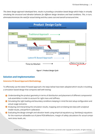

The document describes a FE-based methodology for simulating the vibration behavior of electronic products. This approach establishes calibrated analytical models through FE simulation that correlate well with test data. It has been implemented successfully on real projects, eliminating hardware testing and reducing costs and time. Key steps include understanding product geometry, simulating loads, analyzing results, evaluating design strength, and calibrating models to test data.